ASRock P67 Pro User Manual
ASRock P67 Pro Manual
 |
View all ASRock P67 Pro manuals
Add to My Manuals
Save this manual to your list of manuals |
ASRock P67 Pro manual content summary:
- ASRock P67 Pro | User Manual - Page 1
P67 Pro User Manual Version 1.0 Published September 2010 Copyright©2010 ASRock INC. All rights reserved. 1 - ASRock P67 Pro | User Manual - Page 2
pro ts, loss of business, loss of data, interruption of business and the like), even if ASRock has been advised of the possibility of such damages arising from any defect or error in the manual ONLY The Lithium battery adopted on this motherboard contains Perchlorate, a toxic substance controlled in - ASRock P67 Pro | User Manual - Page 3
5 1.1 Package Contents 5 1.2 Speci cations 6 1.3 Motherboard Layout 11 1.4 I/O Panel 12 2 Installation 14 2.1 HDDs .... 28 2.13 SATA / SATAII / SATA3 HDD Hot Plug Feature and Operation Guide 29 2.14 Driver Installation Guide 31 2.15 Installing Windows® 7 / 7 64-bit / VistaTM / VistaTM 64 - ASRock P67 Pro | User Manual - Page 4
Health Event Monitoring Screen 52 3.5 Boot Screen 53 3.6 Security Screen 54 3.7 Exit Screen 55 4 Software Support 56 4.1 Install Operating System 56 4.2 Support CD Information 56 4.2.1 Running Support CD 56 4.2.2 Drivers Menu 56 4.2.3 Utilities Menu 56 4.2.4 Contact Information 56 4 - ASRock P67 Pro | User Manual - Page 5
guide to BIOS setup and information of the Support CD. Because the motherboard speci cations and the BIOS software might be updated, the content of this manual will be subject to change without notice. In case any modi cations of this manual occur, the updated version will be available on ASRock - ASRock P67 Pro | User Manual - Page 6
high-quality Conductive Polymer Capacitors) - Supports 2nd Generation Intel® CoreTM i7 / i5 / i3 in LGA1155 Package - Supports Intel® Turbo Boost 2.0 Technology - Supports K-Series unlocked CPU - Supports Hyper-Threading Technology (see CAUTION 1) - Intel® P67 - Dual Channel DDR3 Memory Technology - ASRock P67 Pro | User Manual - Page 7
64Mb AMI BIOS - AMI UEFI Legal BIOS with GUI support - Supports "Plug and Play" - ACPI 1.1 Compliance Wake Up Events - Supports jumperfree - SMBIOS 2.3.1 Support - DRAM, PCH, CPU PLL, VTT, VCCSA Voltage Multi-adjustment - Drivers, Utilities, AntiVirus Software (Trial Version), ASRock Software Suite - ASRock P67 Pro | User Manual - Page 8
motherboard supports Dual Channel Memory Technology. Before you implement Dual Channel Memory Technology, make sure to read the installation guide of memory modules on page 18 for proper installation. 3. DDR3 frequency options may depend on the processor. Only K-Series CPU can support DDR3 overclock - ASRock P67 Pro | User Manual - Page 9
AIWI utility either from ASRock of cial website or ASRock software support CD to your motherboard, and also download the free AIWI Lite from App store to your iPhone/iPod touch. Connecting your PC and apple devices via Bluetooth or WiFi networks, then you can start experiencing the exciting motion - ASRock P67 Pro | User Manual - Page 10
a more personal Internet experience. ASRock motherboards are exclusively equipped with the to adopt three different CPU cooler types, Socket LGA 775, LGA 1155 and LGA 1156. Please be noticed that an EuP ready motherboard and an EuP ready power supply are required. According to Intel's suggestion, the - ASRock P67 Pro | User Manual - Page 11
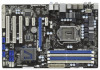
PCIE1 P67 Pro Designed in Taipei 33 PCIE2 PCI Express 2.0 CMOS 32 PCIE3 Battery Super I/O PCIE4 31 30 1 CLRCMOS1 PCI1 Intel P67 CHA_FAN3 2 Power Fan Connector (PWR_FAN1) 20 USB 2.0 Header (USB10_11, Blue) 3 1155-Pin CPU Socket 21 64Mb SPI Flash 4 2 x 240-pin DDR3 DIMM Slots 22 USB - ASRock P67 Pro | User Manual - Page 12
1.4 I/O Panel 1 2 3 6 4 7 5 8 15 14 13 12 11 10 9 1 PS/2 Mouse Port (Green) * 2 LAN RJ-45 Port 3 Side Speaker (Gray) 4 Rear Speaker (Black) 5 Central / Bass (Orange) 6 Line In (Light Blue) ** 7 Front Speaker (Lime) 8 Microphone (Pink) 9 USB 2.0 Ports (USB01) 10 USB 2.0 Ports (USB67) 11 - ASRock P67 Pro | User Manual - Page 13
To enable Multi-Streaming function, you need to connect a front panel audio cable to the front panel audio header. After restarting your computer, you will nd "Mixer" tool on your system. Please select "Mixer ToolBox" , click "Enable playback multi-streaming", and click "ok". Choose "2CH", "4CH - ASRock P67 Pro | User Manual - Page 14
Precautions Take note of the following precautions before you install motherboard components or change any motherboard settings. 1. Unplug the power cord from the wall socket before touching any component. 2. To avoid damaging the motherboard components due to static electricity, NEVER place your - ASRock P67 Pro | User Manual - Page 15
the installation of Intel 1155-Pin CPU, please follow the steps below. Load Plate Load Lever Contact Array Socket Body 1155-Pin Socket Overview Before you insert the 1155-Pin CPU into the socket, please check if cap. 2. This cap must be placed if returning the motherboard for after service. 15 - ASRock P67 Pro | User Manual - Page 16
Heat Sink) up. Locate Pin1 and the two orientation key notches. orientation key notch alignment key Pin1 Pin1 orientation key notch 1155-Pin CPU alignment key 1155-Pin Socket For proper inserting, please ensure to match the two orientation key notches of the CPU with the two alignment keys of - ASRock P67 Pro | User Manual - Page 17
2.4 Installation of CPU Fan and Heatsink This motherboard is equipped with 1155-Pin socket that supports Intel 1155-Pin CPU. Please adopt the type of heatsink and cooling fan compliant with Intel 1155Pin CPU to dissipate heat. Before you installed the heatsink, you need to spray thermal interface - ASRock P67 Pro | User Manual - Page 18
Memory Modules (DIMM) This motherboard provides four 240-pin DDR3 (Double Data Rate 3) DIMM slots, and supports Dual Channel Memory Technology. module or three memory modules are installed in the DDR3 DIMM slots on this motherboard, it is unable to activate the Dual Channel Memory Technology. 3. If a - ASRock P67 Pro | User Manual - Page 19
matches the break on the slot. notch break notch break The DIMM only ts in one correct orientation. It will cause permanent damage to the motherboard and the DIMM if you force the DIMM into the slot at incorrect orientation. Step 3. Firmly insert the DIMM into the slot until the retaining - ASRock P67 Pro | User Manual - Page 20
of the expansion card and make necessary hardware settings for the card before you start the installation. Remove the system unit cover (if your motherboard is already installed in a chassis). Remove the bracket facing the slot that you intend to use. Keep the screws for later use. Align the - ASRock P67 Pro | User Manual - Page 21
need to clear the CMOS when you just nish updating the BIOS, you must boot up the system rst, and then shut it down before you do the clear-CMOS action. Please be noted that the password, date, time, user default pro le, 1394 GUID and MAC address will be cleared only if the - ASRock P67 Pro | User Manual - Page 22
over the headers and connectors will cause permanent damage of the motherboard! FDD connector (33-pin FLOPPY1) (see p.11 No. Data Cable (Optional) SATA3_0 SATA3_1 These two Serial ATA3 (SATA3) connectors support SATA data cables for internal storage devices. The current SATA3 interface allows - ASRock P67 Pro | User Manual - Page 23
panel, there are three USB 2.0 headers on this motherboard. Each USB 2.0 header can support two USB 2.0 ports. Infrared Module Header (5-pin supports Jack Sensing, but the panel wire on the chassis must support HDA to function correctly. Please follow the instruction in our manual and chassis manual - ASRock P67 Pro | User Manual - Page 24
System Panel Header (9-pin PANEL1) (see p.11 No. 15) This header accommodates several system front panel functions. Connect the power switch, reset switch and system status indicator on the chassis to this header according to the pin assignments below. Note the positive and negative pins before - ASRock P67 Pro | User Manual - Page 25
FAN_SPEED_CONTROL Please connect the CPU fan cable to the connector and match the black wire to the ground pin. Though this motherboard provides 4-Pin CPU fan (Quiet Fan) support, the 3-Pin CPU fan still can work successfully even without the fan speed control function. If you plan to connect the - ASRock P67 Pro | User Manual - Page 26
Please connect an ATX 12V power supply to this connector. Though this motherboard provides 8-pin ATX 12V power connector, it can still work if you 26) 4-Pin ATX 12V Power Supply Installation 8 4 This COM1 header supports a serial port module. HDMI_SPDIF Header (2-pin HDMI_SPDIF1) (see p.11 - ASRock P67 Pro | User Manual - Page 27
Disks Installation This motherboard adopts Intel® P67 chipset that supports Serial ATA3 (SATA3) hard disks and RAID (RAID 0, RAID 1, RAID 10, RAID 5 and Intel Rapid Storage) functions. You may install SATA3 hard disks on this motherboard for internal storage devices. This section will guide you to - ASRock P67 Pro | User Manual - Page 28
and in working condition. 2.12 Hot Plug and Hot Swap Functions for SATA3 HDDs This motherboard supports Hot Plug and Hot Swap functions for SATA3 in RAID / AHCI mode. Intel® P67 chipset provides hardware support for Advanced Host controller Interface (AHCI), a new programming interface for SATA host - ASRock P67 Pro | User Manual - Page 29
installed into system properly. The latest SATA / SATAII / SATA3 driver is available on our support website: www.asrock.com 4. Make sure to use the SATA power cable & data cable, which are from our motherboard package. 5. Please follow below instructions step by step to reduce the risk of HDD crash - ASRock P67 Pro | User Manual - Page 30
cable to (White) to the power supply 1x4-pin cable. the motherboard's SATAII / SATA3 connector. SATA power cable 1x4-pin power connector ( of attention, before you process the Hot Unplug: Please do follow below instruction sequence to process the Hot Unplug, improper procedure will cause the SATA - ASRock P67 Pro | User Manual - Page 31
HDDs with RAID functions, please follow below steps. STEP 1: Set up BIOS. A. Enter BIOS SETUP UTILITY Advanced screen SATA Con guration. B. Set the option "SATA Mode" to [RAID]. STEP 2: Make a SATA / SATAII / SATA3 Driver Diskette. A. Insert the Support CD into your optical drive to boot your system - ASRock P67 Pro | User Manual - Page 32
in the support CD, "Guide to Intel Rapid Storage", which is located in the folder at the following path: .. \ Intel Rapid Storage Information If you want to use "Intel Rapid Storage" in Windows® environment, please install "SATAII driver" from the Support CD again so that "Intel Rapid Storage - ASRock P67 Pro | User Manual - Page 33
5. Finish the Windows® installation and install all necessary drivers. 6. Install the Intel(R) Rapid Storage software via the CD-ROM included with your motherboard or after downloading it from the Internet. This will add the Intel(R) Rapid Storage Console which can be used to manage the RAID con - ASRock P67 Pro | User Manual - Page 34
in the support CD, "Guide to Intel Rapid Storage", which is located in the folder at the following path: .. \ Intel Rapid Storage Information If you want to use "Intel Rapid Storage" in Windows® environment, please install "SATAII driver" from the Support CD again so that "Intel Rapid Storage - ASRock P67 Pro | User Manual - Page 35
diskette containing the Intel® AHCI driver. After reading the oppy disk, the driver will be presented. Select the driver to install according to the mode you choose and the OS you install. Using SATA / SATAII / SATA3 HDDs without NCQ function STEP 1: Set up BIOS. A. Enter BIOS SETUP UTILITY Advanced - ASRock P67 Pro | User Manual - Page 36
® 7 / 7 64-bit / VistaTM / VistaTM 64-bit OS on your system. Using SATA / SATAII / STA3 HDDs without NCQ function STEP 1: Set up BIOS. A. Enter BIOS SETUP UTILITY Advanced screen SATA Con guration. B. Set the option "SATA Mode" to [IDE]. STEP 2: Install Windows® 7 / 7 64-bit / VistaTM / VistaTM - ASRock P67 Pro | User Manual - Page 37
UEFI SETUP UTILITY to con gure your system. The UEFI chip on the motherboard stores the UEFI SETUP UTILITY. You may run the UEFI SETUP UTILITY when and then back on. Because the UEFI software is constantly being updated, the following UEFI setup screens and descriptions are for reference purpose - ASRock P67 Pro | User Manual - Page 38
3.1.2 Navigation Keys Please check the following table for the function description of each navigation key. Navigation Key(s) Function Description / / + / Moves cursor left or right to select Screens Moves cursor up or down to select items To change option for the - ASRock P67 Pro | User Manual - Page 39
. Setting wrong values in this section may cause the system to malfunction. ASRock Instant Flash ASRock Instant Flash is a UEFI flash utility embedded in Flash ROM. This convenient UEFI update tool allows you to update system UEFI without entering operating systems rst like MS-DOS or Windows®. Just - ASRock P67 Pro | User Manual - Page 40
options: [Auto] and [Manual]. The default value is [Auto]. Turbo Mode Extra Voltage (mV) Use this item to add voltage when CPU is in Turbo mode. Intel Hyper Threading Technology To enable this feature, it requires a computer system with an Intel processor that supports Hyper-Threading technology and - ASRock P67 Pro | User Manual - Page 41
processors support the Halt State (C1). The C1 state is supported through the native processor instructions HLT and MWAIT and requires no hardware support from the chipset. In the C1 power state, the processor to keep the CPU from overheated. Intel Virtualization Technology When this option is set - ASRock P67 Pro | User Manual - Page 42
3.3.2 Integrated Clock Chip Configuration DIV-1S Integrated Clock Control options. DIV-2S Integrated Clock Control options. DIV3 Integrated Clock Control options. DIV4 Integrated Clock Control options. DIV-1NS Integrated Clock Control options. DIV-2NS Integrated Clock Control options. 42 - ASRock P67 Pro | User Manual - Page 43
le 1] and [Pro le 2]. The default value is [Auto]. DRAM Frequency If [Auto] is selected, the motherboard will detect the memory module(s) inserted and assigns appropriate frequency automatically. CAS# Latency (tCL) Use this item to change CAS# Latency (tCL) Auto/Manual setting. The default is [Auto - ASRock P67 Pro | User Manual - Page 44
]. Write to Read Delay (tWTR) Use this item to change Write to Read Delay (tWTR) Auto/Manual setting. The default is [Auto]. Read to Precharge (tRTP) Use this item to change Read to Precharge (tRTP) Auto/Manual setting. The default is [Auto]. Four Activate Window (tFAW) Use this item to change Four - ASRock P67 Pro | User Manual - Page 45
Low MMIO Align Low MMIO resources align at 64MB/1024MB. The default value is [64MB]. VT-d Use this to enable or disable Intel® VT-d technology (Intel® Virtualization Technology for Directed I/O). The default value of this feature is [Disabled]. Primary Graphics Adapter This allows you to select [PCI - ASRock P67 Pro | User Manual - Page 46
when the power recovers. Deep Sx Mobile platforms support Deep S4/S5 in DC only and desktop platforms support Deep S4/S5 in AC only. Con guration options Please set this option to [Enabled] if you plan to use this motherboard to submit Windows® VistaTM certi cation. Onboard LAN This allows you to - ASRock P67 Pro | User Manual - Page 47
mode. Con guration options: [IDE Mode], [AHCI Mode] and [RAID Mode]. The default value is [IDE Mode]. AHCI (Advanced Host Controller Interface) supports NCQ and other new features that will improve SATA disk performance but IDE mode does not have these advantages. SATA Controller 0 Please select - ASRock P67 Pro | User Manual - Page 48
3.3.7 Super IO Configuration OnBoard Floppy Controller Use this item to enable or disable oppy drive controller. Serial Port Use this item to enable or disable the onboard serial port. Serial Port Address Use this item to set the address for the onboard serial port or disable it. Con guration - ASRock P67 Pro | User Manual - Page 49
3.3.8 Voltage Configuration CPU Core Voltage Offset Use this to select CPU Core Voltage Offset. Con guration options: [Auto], [+0.005V] to [+0.300V]. The default value is [Auto]. DRAM Voltage Use this to select DRAM Voltage. Con guration options: [Auto], [1.200V] to [2.040V]. The default value is [ - ASRock P67 Pro | User Manual - Page 50
RAM Use this item to select whether to auto-detect or disable the Suspend-toRAM feature. Select [Auto] will enable this feature if the OS supports it. PS/2 Keyboard Power On Use this item to enable or disable PS/2 keyboard to turn on the system from the power-soft-off mode - ASRock P67 Pro | User Manual - Page 51
3.3.10 USB Configuration USB 2.0 Controller Use this item to enable or disable the use of USB 2.0 controller. Legacy USB Support Use this option to select legacy support for USB devices. There are four con guration options: [Enabled], [Auto], [Disabled] and [UEFI Setup Only]. The default value is [ - ASRock P67 Pro | User Manual - Page 52
the hardware on your system, including the parameters of the CPU temperature, motherboard temperature, CPU fan speed, chassis fan speed, and the critical voltage. 1 speed. Con guration options: [Full On], [Automatic Mode] and [Manual Mode]. The default is value [Full On]. Chassis Fan 2 Setting This - ASRock P67 Pro | User Manual - Page 53
3.5 Boot Screen In this section, it will display the available devices on your system for you to con gure the boot settings and the boot priority. Bootup Num-Lock If this item is set to [On], it will automatically activate the Numeric Lock function after boot-up. Full Screen Logo Use this item to - ASRock P67 Pro | User Manual - Page 54
3.6 Security Screen In this section, you may set or change the supervisor/user password for the system. For the user password, you may also clear it. 54 - ASRock P67 Pro | User Manual - Page 55
3.7 Exit Screen Save Changes and Exit When you select this option, it will pop-out the following message, "Save con guration changes and exit setup?" Select [OK] to save the changes and exit the UEFI SETUP UTILITY. Discard Changes and Exit When you select this option, it will pop-out the following - ASRock P67 Pro | User Manual - Page 56
install the necessary drivers to activate the devices. 4.2.3 Utilities Menu The Utilities Menu shows the applications software that the motherboard supports. Click on a speci c item then follow the installation wizard to install it. 4.2.4 Contact Information If you need to contact ASRock or want to - ASRock P67 Pro | User Manual - Page 57
Installing OS on a HDD Larger Than 2TB This motherboard is adopting UEFI BIOS that allows Windows® OS to be installed on a large size HDD (>2TB). Please follow below procedure to install the operating system. 1. Please make sure to
-
 1
1 -
 2
2 -
 3
3 -
 4
4 -
 5
5 -
 6
6 -
 7
7 -
8
-
9
-
10
-
11
-
12
-
13
-
14
-
15
-
16
-
17
-
18
-
19
-
20
-
21
-
22
-
23
-
24
-
25
-
26
-
27
-
28
-
29
-
30
-
31
-
32
-
33
-
34
-
35
-
36
-
37
-
38
-
39
-
40
-
41
-
42
-
43
-
44
-
45
-
46
-
47
-
48
-
49
-
50
-
51
-
52
-
53
-
54
-
55
-
56
-
57
 |
 |

1
P67 Pro
User Manual
Version 1.0
Published September 2010
Copyright©2010 ASRock INC. All rights reserved.