ASRock P67 Transformer User Manual
ASRock P67 Transformer Manual
 |
View all ASRock P67 Transformer manuals
Add to My Manuals
Save this manual to your list of manuals |
ASRock P67 Transformer manual content summary:
- ASRock P67 Transformer | User Manual - Page 1
P67 Transformer User Manual Version 1.0 Published December 2010 Copyright©2010 ASRock INC. All rights reserved. 1 - ASRock P67 Transformer | User Manual - Page 2
purchaser for backup purpose, without written consent of ASRock Inc. Products and corporate names appearing in this manual may or may not be registered trademarks or copyrights , USA ONLY The Lithium battery adopted on this motherboard contains Perchlorate, a toxic substance controlled in Perchlorate - ASRock P67 Transformer | User Manual - Page 3
22 2.8 Onboard Headers and Connectors 23 2.9 Smart Switches 28 2.10 Dr. Debug 29 2.11 Serial ATA (SATA) / Serial ATAII and Operation Guide 35 2.16 Driver Installation Guide 37 2.17 Installing Windows® 7 / 7 64-bit / VistaTM / VistaTM 64-bit With RAID Functions 37 2.18 Installing Windows® 7 - ASRock P67 Transformer | User Manual - Page 4
SETUP UTILITY 40 3.1 Introduction 40 3.1.1 UEFI Menu Bar 40 3.1.2 Navigation Keys 41 3.2 Main Screen 41 3.3 OC 3.8 Exit Screen 59 4 Software Support 60 4.1 Install Operating System 60 4.2 Support CD Information 60 4.2.1 Running Support CD 60 4.2.2 Drivers Menu 60 4.2.3 Utilities Menu 60 - ASRock P67 Transformer | User Manual - Page 5
ASRock P67 Transformer Motherboard (ATX Form Factor: 12.0-in x 8.6-in, 30.5 cm x 21.8 cm) ASRock P67 Transformer Quick Installation Guide ASRock P67 Transformer Support CD 2 x Serial ATA (SATA) Data Cables (Optional) 1 x I/O Panel Shield ASRock Reminds You... To get better performance in Windows - ASRock P67 Transformer | User Manual - Page 6
CoreTM i7 / i5 Processors in LGA1156 Package - Advanced V8 + 2 Power Phase Design - Supports Intel® Turbo Boost Technology - Supports Hyper-Threading Technology (see CAUTION 1) - Supports Untied Overclocking Technology (see CAUTION 2) - Intel® P67 - Dual Channel DDR3 Memory Technology (see CAUTION - ASRock P67 Transformer | User Manual - Page 7
LED - 64Mb AMI BIOS - AMI UEFI Legal BIOS with GUI support - Supports "Plug and Play" - ACPI 1.1 Compliance Wake Up Events - Supports jumperfree - SMBIOS 2.3.1 Support - DRAM, PCH, CPU PLL, VTT Voltage Multi-adjustment - Supports I. O. T. (Intelligent Overclocking Technology) - Drivers, Utilities - ASRock P67 Transformer | User Manual - Page 8
visit our website: http://www.asrock.com WARNING Please realize that there is a certain risk involved with overclocking, including adjusting the setting in the BIOS, applying Untied Overclocking Technology, or using the third-party overclocking tools. Overclocking may affect your system stability - ASRock P67 Transformer | User Manual - Page 9
procedures of ASRock Extreme Tuning Utility (AXTU). ASRock website: http://www.asrock.com 7. ASRock Instant Flash is a BIOS ash utility embedded in Flash ROM. This convenient BIOS update tool allows you to update system BIOS without entering operating systems rst like MS-DOS or Windows®. With this - ASRock P67 Transformer | User Manual - Page 10
game joystick to control your PC games. All you have to do is just to install the ASRock AIWI utility either from ASRock of cial website or ASRock software support CD to your motherboard CPU cooler types, Socket LGA 775 and LGA 1156. Please benoticed that not all the 775 CPU Fan can be used. 10 - ASRock P67 Transformer | User Manual - Page 11
to EuP, the total AC power of the completed system shall be under 1.00W in off mode condition. To meet EuP standard, an EuP ready motherboard and an EuP ready power supply are required. According to Intel's suggestion, the EuP ready power supply must meet the standard of 5v standby power - ASRock P67 Transformer | User Manual - Page 12
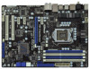
CPU_FAN1 PCIE1 CHA_FAN3 P67 Transformer PCIE2 PCI Express 2.0 SATA3 6Gb/s ErP/EuP Ready JMicron JMB363 PCIE3 PCIE4 Intel P67 64Mb BIOS AUDIO CODEC HD_AUDIO1 7 8 9 10 11 12 13 14 15 16 17 18 19 20 21 22 1 ATX 12V Power Connector (ATX12V1) 21 Dr. Debug 2 1156-Pin CPU Socket 22 Power Switch - ASRock P67 Transformer | User Manual - Page 13
RJ-45 Port 5 Side Speaker (Gray) 6 Rear Speaker (Black) 7 Central / Bass (Orange) 8 Line In (Light Blue) ** 9 Front Speaker (Lime) 13 12 11 10 Microphone (Pink) 11 USB 2.0 Ports (USB45) 12 USB 3.0 Ports (USB23) 13 USB 2.0 Ports (USB01) 14 eSATA2 Connector (eSATAII_1) 15 Optical SPDIF Out Port 16 - ASRock P67 Transformer | User Manual - Page 14
To enable Multi-Streaming function, you need to connect a front panel audio cable to the front panel audio header. After restarting your computer, you will nd "Mixer" tool on your system. Please select "Mixer ToolBox" , click "Enable playback multi-streaming", and click "ok". Choose "2CH", "4CH - ASRock P67 Transformer | User Manual - Page 15
Precautions Take note of the following precautions before you install motherboard components or change any motherboard settings. 1. Unplug the power cord from the wall socket before touching any component. 2. To avoid damaging the motherboard components due to static electricity, NEVER place your - ASRock P67 Transformer | User Manual - Page 16
Socket Body 1156-Pin Socket Overview Before you insert the 1156-Pin CPU into the socket, please check if the CPU surface is unclean or if there is any bent pin on the socket. Do not force to insert the CPU into the socket 2. This cap must be placed if returning the motherboard for after service. 16 - ASRock P67 Transformer | User Manual - Page 17
Heat Sink) up. Locate Pin1 and the two orientation key notches. orientation key notch alignment key Pin1 Pin1 orientation key notch 1156-Pin CPU alignment key 1156-Pin Socket For proper inserting, please ensure to match the two orientation key notches of the CPU with the two alignment keys of - ASRock P67 Transformer | User Manual - Page 18
interfere with fan operation or contact other components. Please be noticed that this motherboard supports Combo Cooler Option (C.C.O.), which provides the exible option to adopt two different CPU cooler types, Socket LGA 775 and LGA 1156. The white throughholes are for Socket LGA 1156 CPU fan. 18 - ASRock P67 Transformer | User Manual - Page 19
of Memory Modules (DIMM) This motherboard provides four 240-pin DDR3 (Double Data Rate 3) DIMM slots, and supports Dual Channel Memory Technology. For dual channel con- guration, you always need to install identical (the same brand, speed, size and chiptype) DDR3 DIMM pair in the slots of - ASRock P67 Transformer | User Manual - Page 20
matches the break on the slot. notch break notch break The DIMM only ts in one correct orientation. It will cause permanent damage to the motherboard and the DIMM if you force the DIMM into the slot at incorrect orientation. Step 3. Firmly insert the DIMM into the slot until the retaining - ASRock P67 Transformer | User Manual - Page 21
of the expansion card and make necessary hardware settings for the card before you start the installation. Remove the system unit cover (if your motherboard is already installed in a chassis). Remove the bracket facing the slot that you intend to use. Keep the screws for later use. Align the - ASRock P67 Transformer | User Manual - Page 22
need to clear the CMOS when you just nish updating the BIOS, you must boot up the system rst, and then shut it down before you do the clear-CMOS action. Please be noted that the password, date, time, user default pro le, 1394 GUID and MAC address will be cleared only if - ASRock P67 Transformer | User Manual - Page 23
end to the motherboard connect the black end to the IDE devices 80-conductor ATA 66/100/133 cable Note: Please refer to the instruction of your IDE device 12, No. 10) Serial ATA (SATA) Data Cable (Optional) SATAIII_1 SATAIII_0 These two Serial ATA3 (SATA3) connectors support SATA data cables - ASRock P67 Transformer | User Manual - Page 24
GND DUMMY 1 GND P+12 P-12 USB_PWR Besides six default USB 2.0 ports on the I/O panel, there are three USB 2.0 headers on this motherboard. Each USB 2.0 header can support two USB 2.0 ports. Infrared Module Header (5-pin IR1) (see p.12 No. 29) Internal Audio Connectors (4-pin CD1) (CD1: see p.12 No - ASRock P67 Transformer | User Manual - Page 25
on the chassis must support HDA to function correctly. Please follow the instruction in our manual and chassis manual to install your system. E. To activate the front mic. For Windows® XP / XP 64-bit OS: Select "Mixer". Select "Recorder". Then click "FrontMic". For Windows® 7 / 7 64-bit / VistaTM - ASRock P67 Transformer | User Manual - Page 26
FAN_SPEED_CONTROL Please connect the CPU fan cable to the connector and match the black wire to the ground pin. Though this motherboard provides 4-Pin CPU fan (Quiet Fan) support, the 3-Pin CPU fan still can work successfully even without the fan speed control function. If you plan to connect the - ASRock P67 Transformer | User Manual - Page 27
connect an ATX power supply to this connector. 1 13 Though this motherboard provides 24-pin ATX power connector, 12 24 it can still work No. 30) 4-Pin ATX 12V Power Supply Installation 4 1 This COM1 header supports a serial port module. HDMI_SPDIF Header (2-pin HDMI_SPDIF1) (see p.12 No. - ASRock P67 Transformer | User Manual - Page 28
2.9 Smart Switches The motherboard has three smart switches: power switch, reset switch and clear CMOS switch, allowing users to quickly turn on/off or reset the sytem clear the - ASRock P67 Transformer | User Manual - Page 29
2.10 Dr. Debug Dr. Debug is used to provide code information, which makes troubleshooting even easier. Please see the diagrams below for reading the Dr. Debug codes. Status Code 0x00 0x01 0x02 0x03 0x04 0x05 0x06 0x07 0x08 0x09 - ASRock P67 Transformer | User Manual - Page 30
detected Unspeci ed memory initialization error Memory not installed Invalid CPU type or Speed CPU mismatch CPU self test failed or possible CPU cache error CPU micro-code is not found or micro-code update is failed Internal CPU error reset PPI is not available Reserved for future AMI error codes S3 - ASRock P67 Transformer | User Manual - Page 31
- 0x9F 0xA0 0xA1 0xA2 0xA3 0xA4 0xA5 Installation of the South Bridge Runtime Services CPU DXE initialization is started CPU DXE initialization (CPU module speci c) CPU codes Boot Device Selection (BDS) phase is started Driver connecting is started PCI Bus initialization is started PCI Bus - ASRock P67 Transformer | User Manual - Page 32
(see ASL Status Codes section below) Ready To Boot event Legacy Boot event Exit Boot Services event Runtime Set Virtual Address MAP Begin Runtime Set Virtual Address MAP End Legacy Option ROM Boot Option is failed (StartImage returned error) Flash update is failed Reset protocol is not available 32 - ASRock P67 Transformer | User Manual - Page 33
Disks Installation This motherboard adopts Intel® P67 chipset that supports Serial ATA3 (SATA3) hard disks and RAID (RAID 0, RAID 1, RAID 10, RAID 5 and Intel Rapid Storage) functions. You may install SATA3 hard disks on this motherboard for internal storage devices. This section will guide you to - ASRock P67 Transformer | User Manual - Page 34
and in working condition. 2.14 Hot Plug and Hot Swap Functions for SATA3 HDDs This motherboard supports Hot Plug and Hot Swap functions for SATA3 in RAID / AHCI mode. Intel® P67 chipset provides hardware support for Advanced Host controller Interface (AHCI), a new programming interface for SATA host - ASRock P67 Transformer | User Manual - Page 35
installed into system properly. The latest SATA / SATAII / SATA3 driver is available on our support website: www.asrock.com 4. Make sure to use the SATA power cable & data cable, which are from our motherboard package. 5. Please follow below instructions step by step to reduce the risk of HDD crash - ASRock P67 Transformer | User Manual - Page 36
cable to (White) to the power supply 1x4-pin cable. the motherboard's SATAII / SATA3 connector. SATA power cable 1x4-pin power connector ( of attention, before you process the Hot Unplug: Please do follow below instruction sequence to process the Hot Unplug, improper procedure will cause the SATA - ASRock P67 Transformer | User Manual - Page 37
to the OS you install. RAID mode is not supported under Windows® XP / XP 64-bit OS. STEP 1: Set up UEFI. A. Enter UEFI SETUP UTILITY Advanced screen Storage Con guration. B. Set the option "SATA Mode" to [RAID]. STEP 2: Use "RAID Installation Guide" to set RAID configuration. Before you start - ASRock P67 Transformer | User Manual - Page 38
OS on your SATA / SATAII / SATA3 HDDs without RAID functions, please follow below steps. AHCI mode is not supported under Windows® XP / XP 64-bit OS. Using SATA / SATAII / SATA3 HDDs without NCQ function STEP 1: Set up UEFI. A. Enter UEFI SETUP UTILITY Advanced screen Storage Con guration. B. Set - ASRock P67 Transformer | User Manual - Page 39
This motherboard supports Untied Overclocking Technology, which means during overclocking, FSB enjoys better margin due to xed PCI / PCIE buses. Before you enable Untied Overclocking function, please enter "Overclock Mode" option of BIOS setup to set the selection from [Auto] to [Manual]. Therefore - ASRock P67 Transformer | User Manual - Page 40
UEFI chip on the motherboard stores the UEFI SETUP UTILITY. You may run the UEFI SETUP UTILITY when you start up the computer. Please press or during the Power-On-Self-Test (POST) to enter the UEFI To set up overclocking features Advanced To set up the advanced UEFI features H/W Monitor - ASRock P67 Transformer | User Manual - Page 41
up the selected screen To display the General Help Screen To load optimal default values for all the settings To save changes and exit the UEFI SETUP UTILITY To jump to the Exit Screen or exit the current screen 3.2 Main Screen When you enter the - ASRock P67 Transformer | User Manual - Page 42
Use this item to change the ratio value of this motherboard. Overclock Mode Use this to select Overclock Mode. Con guration options: [Auto], [Manual], [I.O.T.] and [Optimized]. The default value is [Auto]. If you select [Manual], Untied Overclocking function is enabled. Please refer to page 39 for - ASRock P67 Transformer | User Manual - Page 43
]. Read to Precharge (tRTP) Use this item to change Read to Precharge (tRTP) Auto/Manual setting. The default is [Auto]. Four Activate Window (tFAW) Use this item to change Four Activate Window (tFAW) Auto/Manual setting. The default is [Auto]. DRAM Command Rate Use this item to change Command Rate - ASRock P67 Transformer | User Manual - Page 44
[2.059V]. The default value is [Auto]. ASRock Vdroop Control Use this to enable or disable ASRock Vdroop control. Con guration options: [With] to enable this function, please set this item to [Enabled]. Besides the UEFI option, you can also choose our Intelligent Energy Saver utility to enable this - ASRock P67 Transformer | User Manual - Page 45
section may cause the system to malfunction. ASRock Instant Flash ASRock Instant Flash is a UEFI flash utility embedded in Flash ROM. This convenient UEFI update tool allows you to update system UEFI without entering operating systems rst like MS-DOS or Windows®. Just launch this tool and save the - ASRock P67 Transformer | User Manual - Page 46
Use this item to change the ratio value of this motherboard. Intel SpeedStep Technology Intel SpeedStep technology is Intel's new install Windows® VistaTM / 7 and want to enable this function, please set this item to [Enabled]. This item will be hidden if the current CPU does not support Intel - ASRock P67 Transformer | User Manual - Page 47
on/off prefetching of adjacent cache lines. Enhance Halt State (C1E) All processors support the Halt State (C1). The C1 state is supported through the native processor instructions HLT and MWAIT and requires no hardware support from the chipset. In the C1 power state, the processor maintains the - ASRock P67 Transformer | User Manual - Page 48
], [I.O.T.] and [Optimized]. The default value is [Auto]. If you select [Manual], Untied Overclocking function is enabled. Please refer to page 39 for the details of Untied Overclocking Technology. Therefore, you are allowed to adjust the BCLK frequency and PCIE frequency in the following two items - ASRock P67 Transformer | User Manual - Page 49
3.4.3 North Bridge Configuration Primary Graphics Adapter This allows you to select [PCI] or [PCI Express] as the boot graphic adapter priority. The default value is [PCI Express]. VT-d Use this to enable or disable Intel® VT-d technology (Intel® Virtualization Technology for Directed I/O). The - ASRock P67 Transformer | User Manual - Page 50
when the power recovers. Deep Sx Mobile platforms support Deep S4/S5 in DC only and desktop platforms support Deep S4/S5 in AC only. Con guration set this option to [Enabled] if you plan to use this motherboard to submit Windows® VistaTM certi cation. Good Night LED Enable this option to turn - ASRock P67 Transformer | User Manual - Page 51
Mode], [AHCI Mode] and [RAID Mode]. The default value is [IDE Mode]. AHCI (Advanced Host Controller Interface) supports NCQ and other new features that 1 Please select [Compatible] when you install legacy OS. If native OS (Windows® XP / VistaTM / 7) is installed, please select [Enhanced]. Hard Disk - ASRock P67 Transformer | User Manual - Page 52
3.4.6 Super IO Configuration Serial Port Use this item to enable or disable the onboard serial port. Serial Port Address Use this item to set the address for the onboard serial port. Infrared Port Use this item to enable or disable the onboard infrared port. Infrared Port Address Use this item to - ASRock P67 Transformer | User Manual - Page 53
114V] to [2.059V]. The default value is [Auto]. ASRock Vdroop Control Use this to enable or disable ASRock Vdroop control. Con guration options: [With] and [Without]. please set this item to [Enabled]. Besides the UEFI option, you can also choose our Intelligent Energy Saver utility to enable this function - ASRock P67 Transformer | User Manual - Page 54
RAM Use this item to select whether to auto-detect or disable the Suspend-toRAM feature. Select [Auto] will enable this feature if the OS supports it. Check Ready Bit Use this item to enable or disable the feature Check Ready Bit. PS/2 Keyboard Power On Use this item to enable - ASRock P67 Transformer | User Manual - Page 55
compatibility issue, it is recommended to select [Disabled] to enter OS. [UEFI Setup Only] - USB devices are allowed to use only under UEFI setup and Windows / Linux OS. Legacy USB 3.0 Support Use this option to enable or disable legacy support for USB 3.0 devices. The default value is [Enabled]. 55 - ASRock P67 Transformer | User Manual - Page 56
on your system, including the parameters of the CPU temperature, motherboard temperature, CPU fan speed, chassis fan speed, and the critical to set the chassis fan 1 speed. Con guration options: [Full On] and [Manual Mode]. The default is value [Full On]. Chassis Fan 2 Setting This allows you - ASRock P67 Transformer | User Manual - Page 57
3.6 Boot Screen In this section, it will display the available devices on your system for you to con gure the boot settings and the boot priority. Boot Option Priorities Boot Option #1 Set the rst priority of the system boot device. Hard Drive BBS Priorities Set the order of the legacy devices in - ASRock P67 Transformer | User Manual - Page 58
3.7 Security Screen In this section, you may set or change the supervisor/user password for the system. For the user password, you may also clear it. 58 - ASRock P67 Transformer | User Manual - Page 59
this option, it will pop-out the following message, "Save con guration changes and exit setup?" Select [OK] to save the changes and exit the UEFI SETUP UTILITY. Discard Changes and Exit When you select this option, it will pop-out the following message, "Discard changes and exit setup?" Select [OK - ASRock P67 Transformer | User Manual - Page 60
install the necessary drivers to activate the devices. 4.2.3 Utilities Menu The Utilities Menu shows the applications software that the motherboard supports. Click on a speci c item then follow the installation wizard to install it. 4.2.4 Contact Information If you need to contact ASRock or want to - ASRock P67 Transformer | User Manual - Page 61
HDD Larger Than 2TB This motherboard is adopting UEFI BIOS that allows Windows® OS to be installed on a large size HDD (>2TB). Please follow below procedure to install the operating system. 1. Please make sure to use Windows® VistaTM 64-bit (with SP1 or above) or Windows® 7 64-bit. 2. Set AHCI Mode
-
 1
1 -
 2
2 -
 3
3 -
 4
4 -
 5
5 -
 6
6 -
 7
7 -
8
-
9
-
10
-
11
-
12
-
13
-
14
-
15
-
16
-
17
-
18
-
19
-
20
-
21
-
22
-
23
-
24
-
25
-
26
-
27
-
28
-
29
-
30
-
31
-
32
-
33
-
34
-
35
-
36
-
37
-
38
-
39
-
40
-
41
-
42
-
43
-
44
-
45
-
46
-
47
-
48
-
49
-
50
-
51
-
52
-
53
-
54
-
55
-
56
-
57
-
58
-
59
-
60
-
61
 |
 |

1
P67 Transformer
User Manual
Version 1.0
Published December 2010
Copyright©2010 ASRock INC. All rights reserved.