ASRock PE PRO User Manual
ASRock PE PRO Manual
 |
View all ASRock PE PRO manuals
Add to My Manuals
Save this manual to your list of manuals |
ASRock PE PRO manual content summary:
- ASRock PE PRO | User Manual - Page 1
PE Pro / GE Pro / G Pro A User Manual Published October 2002 Copyright©2002 ASRock INC. All rights reserved. 1 - ASRock PE PRO | User Manual - Page 2
any form or by any means, except duplication of documentation by the purchaser for backup purpose, without written consent of ASRock Inc. Products and corporate names appearing in this manual may or may not be registered trademarks or copyrights of their respective companies, and are used only for - ASRock PE PRO | User Manual - Page 3
Contents 1 Introduction 4 1.1 Package Contents 4 1.2 Specifications 4 1.3 Motherboard Layout (PE Pro 6 1.4 Motherboard Layout (GE Pro 7 1.5 Motherboard Layout (G Pro A 8 1.6 ASRock I/OTM (PE Pro / GE Pro / G Pro A 9 2 Installation 10 2.1 Screw Holes 10 2.2 Pre-installation Precautions 10 - ASRock PE PRO | User Manual - Page 4
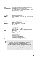
users' reference, the Appendix offers more advanced BIOS setup information. 1.1 Package Contents ASRock PE Pro, GE Pro, or G Pro A motherboard (ATX form factor: 12" x 9.6") ASRock PE Pro / GE Pro / G Pro A Quick Installation Guide ASRock Intel-SiS Series Support CD 1 Cable for IDE devices (1 x ATA - ASRock PE PRO | User Manual - Page 5
CPU overheat is detected, the system will automatically shutdown. Please check if the CPU fan on the motherboard functions properly before you resume the system. 2. Although PE Pro/GE Pro/ G Pro A offers stepless control, it is not recommended to perform over clocking. Frequencies other than the - ASRock PE PRO | User Manual - Page 6
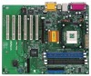
Motherboard Layout (PE Pro Audio CODEC Super I/O 11 2MB BIOS 18 8 7 SiS 645 Chipset Accelerated Graphics Port 01 23 01 23 IDE2 IDE1 25 PCI 1 PCI 2 PCI 3 PCI 4 PCI 5 SiS South Bridge 9 CHA_FAN1 16 PE PRO System panel connector (PANEL1) 13 USB header (USB45) 6 ATA133 USB2.0 5.1CH PANEL - ASRock PE PRO | User Manual - Page 7
CD1 1 Audio1 Audio CODEC Super I/O 11 2MB BIOS 18 Accelerated Graphics Port 01 23 01 23 IDE2 IDE1 25 PCI 1 PCI 2 PCI 3 PCI 4 PCI 5 SiS South Bridge 9 CHA_FAN1 16 GE PRO FLOPPY1 CLRCMOS1 CMOS Battery 1 IR1 1 SPEAKER1 1 USB45 10 14 15 13 17 PCI 6 ATA133 USB2.0 5.1CH PANEL 1 PLED - ASRock PE PRO | User Manual - Page 8
Motherboard Layout (G Pro Audio1 Audio CODEC Super I/O 11 2MB BIOS 18 ATA133 USB2.0 5.1CH PANEL 1 PLED PWRBTN 1 HDLED RST 12 14 Infrared module connector (IR1) 15 Speaker connector (SPEAKER1) 16 South Bridge controller 17 CLRCMOS1 18 PCI slots 19 Audio CODEC 20 Front panel audio - ASRock PE PRO | User Manual - Page 9
1.6 ASRock I/OTM (PE Pro / GE Pro / G Pro A) 1 2 3 10 9 1 Parallel port 2 RJ-45 port 3 Game port 4 Microphone (Pink) 5 Line In (Light Blue) 8 7 65 4 6 Line Out (Lime) 7 USB 2.0 ports 8 Serial port (COM1) 9 PS/2 keyboard port (Purple) 10 PS/2 mouse port (Green) 9 - ASRock PE PRO | User Manual - Page 10
2 Installation PE Pro / GE Pro / G Pro A is an ATX form factor (12" x 9.6") motherboard. Before you install the motherboard, study the configuration of your chassis to ensure that the motherboard fits into it. Make sure to unplug the power cord before installing or removing the motherboard. Failure - ASRock PE PRO | User Manual - Page 11
the CPU and the heatsink are securely fastened and in good contact with each other. For proper installation, please kindly refer to the instruction manuals of the CPU fan and heatsink vendors. 2.5 Installation of Memory Modules (DIMM) SDRAM (Synchronous DRAM) DIMM (Dual In-line Memory Module) has - ASRock PE PRO | User Manual - Page 12
6 PCI slots and 1 AGP slot on both PE Pro and GE Pro motherboards. PCI slots: PCI slots are used to install expansion cards that have the 32-bit PCI interface. AGP slot: The AGP slot is used to install a graphics card. The ASRock - ASRock PE PRO | User Manual - Page 13
(Blue) (39-pin IDE1) (see p.6/p.7/p.8 item 7) Secondary IDE connector (Black) (39-pin IDE2) (see p.6/p.7/p.8 item 8) PIN1 IDE1 Blue Connect to the motherboard PIN1 IDE2 Black Connect to the IDE devices 80-Pin ATA 100/133 cable Note: To optimize compatibility and performance, please connect - ASRock PE PRO | User Manual - Page 14
1 GND IRRX ASRock I/OTM already provided 4 default USB ports. If the 4 USB ports on the rear panel are not sufficient, an USB header is available for 2 additional USB ports. This connector supports an optional wireless transmitting and receiving infrared module. Internal audio connectors (4-pin - ASRock PE PRO | User Manual - Page 15
CPU fan connector (3-pin CPU_FAN1) (see p.6/p.7/p.8 item 3) ATX power connector (20-pin ATXPWR1) (see p.6/p.7/p.8 item 1) VGA header (15-pin VGA1) (see p.7/p.8 item 26) GND +12V CPU_FAN_SPEED Connect the fan cable to the connector matching the black wire to the ground pin. Connect an ATX power - ASRock PE PRO | User Manual - Page 16
BIOS Setup Utility. The Flash Memory on the motherboard stores the BIOS Setup Utility. When you start up the computer, there is a chance for you to run the BIOS the predetermined choices. Because the BIOS software is constantly being updated, the following BIOS setup screens and descriptions are for - ASRock PE PRO | User Manual - Page 17
Version Processor Type Processor Speed Cache Size Microcode Update Total Memory DDR1 DDR2 SDR1 SDR2 AMIBIOS SETUP UTILITY - VERSION 3.31a Security Power Boot Exit Oct 14 2002 Mon 17:07:40 [ Setup Help ] Month: Jan - Dec Day: 01 - 31 Year: 1980 - 2099 GE-PRO BIOS L0.10 Generic-X86 2000 MHz 512 KB - ASRock PE PRO | User Manual - Page 18
may due to that the hard disk is too old or too new. If the hard disk was already formatted on an older system, the BIOS Setup may detect incorrect parameters. In these cases, select [User] to manually enter the IDE hard disk drive parameters. After entering the hard disk information into - ASRock PE PRO | User Manual - Page 19
per track. Refer to the drive documentation to determine the correct value. Maximum Capacity This field shows the drive's maximum capacity as calculated by the BIOS based on the drive information you entered. LBA Mode This allows user to select the LBA mode for a hard disk > 512 MB under DOS and - ASRock PE PRO | User Manual - Page 20
detects installed devices. Install the necessary drivers to activate the devices. 4.2.3 Utilities Menu The Utilities Menu shows the applications software that the motherboard supports. Click on a specific item then follow the installation wizard to install it. 4.2.4 ASRock PC-DIY Live Demo Program - ASRock PE PRO | User Manual - Page 21
]: This allows user to set CPU host frequency manually. However, this is not recommended unless user thoroughly knows the feature. Wrong setup may cause problems during operation. SDRAM Frequency: [Auto]: The motherboard detects the memory module(s) inserted and automatically assigns appropriate - ASRock PE PRO | User Manual - Page 22
: Use this to enable or disable support to emulate legacy I/O devices such as mouse, keyboard,... etc. Resource Configuration: PCI Latency Timer (PCI Clocks): The default is 32. We recommend you to keep - ASRock PE PRO | User Manual - Page 23
audio feature. OnBoard MC'97 Modem: Enable or disable onboard MC'97 modem feature. System Hardware Monitor: You can check the status of the hardware on your system. It allows you to monitor the parameters for CPU temperature, Motherboard Check" is performed before BIOS setup. If [Always] option is selected - ASRock PE PRO | User Manual - Page 24
allows you to select whether to auto-detect or disable the ACPI Suspend-to-RAM feature. Select [Auto] will enable this feature if the system supports it. Repost Video on S3 Resume: This allows you to repost video on S3 resume. Restore on AC/Power Loss: This allows you to set - ASRock PE PRO | User Manual - Page 25
. Boot-time Diagnostic Screen: This screen shows CPU and hardware information during Power-On-Self-Test (POST) routine. If this screen is disabled, only ASRock logo is shown during the boot up process. Boot Up Num-Lock: This automatically activates the Numeric Lock function after boot up. Boot to OS - ASRock PE PRO | User Manual - Page 26
sub-menu, the message "Save current settings and exit" will appear. If you press , it will save the current settings and exit the BIOS SETUP Uutility. Exit Discarding Changes: After you enter the submenu, the message "Quit without saving changes" will appear. If you press , you will
-
 1
1 -
 2
2 -
 3
3 -
 4
4 -
 5
5 -
 6
6 -
 7
7 -
8
-
9
-
10
-
11
-
12
-
13
-
14
-
15
-
16
-
17
-
18
-
19
-
20
-
21
-
22
-
23
-
24
-
25
-
26
 |
 |

1
PE Pro / GE Pro / G Pro A
User Manual
Published October 2002
Copyright©2002 ASRock INC. All rights reserved.