ASRock PV530A User Manual
ASRock PV530A Manual
 |
View all ASRock PV530A manuals
Add to My Manuals
Save this manual to your list of manuals |
ASRock PV530A manual content summary:
- ASRock PV530A | User Manual - Page 1
PV530A User Manual Version 1.0 Published November 2011 Copyright©2011 ASRock INC. All rights reserved. 1 - ASRock PV530A | User Manual - Page 2
any form or by any means, except duplication of documentation by the purchaser for backup purpose, without written consent of ASRock Inc. Products and corporate names appearing in this manual may or may not be registered trademarks or copyrights of their respective companies, and are used only for - ASRock PV530A | User Manual - Page 3
Slot 14 2.5 Jumpers Setup 15 2.6 Onboard Headers and Connectors 16 2.7 SATAII Hard Disk Setup Guide 18 2.8 Serial ATA (SATA) / Serial ATAII (SATAII) Hard Disks Installation 19 2.9 Driver Installation Guide 20 2.10 Untied Overclocking Technology 20 3 BIOS SETUP UTILITY 21 3.1 Introduction 21 - ASRock PV530A | User Manual - Page 4
4 Software Support 39 4.1 Install Operating System 39 4.2 Support CD Information 39 4.2.1 Running Support CD 39 4.2.2 Drivers Menu 39 4.2.3 Utilities Menu 39 4.2.4 Contact Information 39 4 - ASRock PV530A | User Manual - Page 5
specific information about the model you are using. www.asrock.com/support/index.asp 1.1 Package Contents ASRock PV530A Motherboard (Micro ATX Form Factor: 8.5-in x 6.7-in, 21.6 cm x 17.0 cm) ASRock PV530A Quick Installation Guide ASRock PV530A Support CD Two Serial ATA (SATA) Data Cables (Optional - ASRock PV530A | User Manual - Page 6
Rear Panel I/O Connector - Micro ATX Form Factor: 8.5-in x 6.7-in, 21.6 cm x 17.0 cm - Solid Capacitor for CPU power - VIA® PV530 Processor (1.8 GHz) - Supports FSB800 MHz - Supports Untied Overclocking Technology (see CAUTION 1) - VIA® VX900 A3 - 1 x DDR3 DIMM slot - Supports DDR3 800 non-ECC, un - ASRock PV530A | User Manual - Page 7
+5V, +3.3V, Vcore OS - Microsoft® Windows® 7 / VistaTM / XP compliant Certifications - FCC, CE, WHQL - ErP/EuP Ready (ErP/EuP ready power supply is required) (see CAUTION 14) * For detailed product information, please visit our website: http://www.asrock.com WARNING Please realize that there - ASRock PV530A | User Manual - Page 8
40% faster than before. ASRock APP Charger allows you to quickly charge many Apple devices simultaneously and even supports continuous charging when your PC enters into Standby mode (S1), Suspend to RAM (S3), hibernation mode (S4) or power off (S5). With APP Charger driver installed, you can easily - ASRock PV530A | User Manual - Page 9
Windows® 7 / VistaTM, and your browser version is IE8. ASRock website: http://www.asrock.com/Feature/SmartView/index.asp 10. ASRock XFast regulated by European Union to define the power consumption for the completed system. According to EuP, the total AC power of the completed system shall be under - ASRock PV530A | User Manual - Page 10
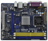
(DDRII_1, DDRII_2; Yellow) (HD_AUDIO1, White) 7 1 x 240-pin DDR3 DIMM Slot (DDR3_1; Blue) 19 Primary SATAII Connector (SATAII_1; Blue) 8 USB 2.0 Header (USB6_7, Blue) 20 Secondary SATAII Connector (SATAII_2; Blue) 9 USB 2.0 Header (USB4_5, Blue) 21 VIA VX900 A3 Chipset 10 BIOS SPI Chip 22 - ASRock PV530A | User Manual - Page 11
follow below instructions according to the OS you install. For Windows® XP OS: Please click "VIA HD Audio Deck" icon , and click "Speaker". Then you are allowed to select "2 Channel" or "4 Channel". Click "Power" to save your change. For Windows® 7 / VistaTM OS: Please click "VIA HD Audio - ASRock PV530A | User Manual - Page 12
Chapter 2 Installation PV530A is a Micro ATX form factor (8.5" x 6.7", 21.6 x 17.0 cm) motherboard. Before you install the motherboard, study the configuration of your chassis to ensure that the motherboard fits into it. Make sure to unplug the power cord before installing or removing the - ASRock PV530A | User Manual - Page 13
and DIMM may be damaged. 2. Please do not use the DDR2 slots and DDR3 slot at the same time. You can choose to install either DDR2 or DDR3 memory module. Installing a DIMM Please make sure to disconnect power supply before adding or removing DIMMs or the system components. Step 1. Unlock a DIMM - ASRock PV530A | User Manual - Page 14
x16 lane width graphics card. Installing an expansion card Step 1. Before installing the expansion card, please make sure that the power supply is switched off or the power cord is unplugged. Please read the documentation of the expansion card and make necessary hardware settings for the card before - ASRock PV530A | User Manual - Page 15
pin3 to enable +5VSB (standby) for PS/2 or USB23 wake up events. Note: To select +5VSB, it requires 2 Amp and higher standby current provided by power supply. USB_PWR2 (see p.10, No. 22) 1_2 Short pin2, pin3 to enable +5V_DUAL for USB01 wake +5V +5V_DUAL up events. Note: To select +5V_DUAL - ASRock PV530A | User Manual - Page 16
allows convenient connection and control of audio devices. 1. High Definition Audio supports Jack Sensing, but the panel wire on the chassis must support HDA to function correctly. Please follow the instruction in our manual and chassis manual to install your system. 2. If you use AC'97 audio panel - ASRock PV530A | User Manual - Page 17
(see p.10, No. 3) Please connect an ATX power 13 supply to this connector. 1 Though this motherboard provides 24-pin ATX power connector, it can still work if you adopt a traditional 20-pin ATX power supply. To use the 20-pin ATX power supply, please plug your power supply along with Pin 1 and Pin - ASRock PV530A | User Manual - Page 18
guide. Some default setting of SATAII hard disks may not be at SATAII mode, which operate with the best performance. In order to enable SATAII function, please follow the below instruction website for details: http://www.hitachigst.com/hdd/support/download.htm The above examples are just for your - ASRock PV530A | User Manual - Page 19
(SATAII) Hard Disks Installation This motherboard adopts VIA® VX900 A3 chipset that supports Serial ATA (SATA) / Serial ATAII (SATAII) hard disks. You may install SATA / SATAII hard disks on this motherboard for internal storage devices. This section will guide you to install the SATA / SATAII hard - ASRock PV530A | User Manual - Page 20
2.9 Driver Installation Guide To install the drivers to your system, please insert the support CD to your optical drive first. Then, the drivers compatible to your system can be auto-detected and listed on the support CD driver page. Please follow the order from up to bottom side to install those - ASRock PV530A | User Manual - Page 21
stores the BIOS SETUP UTILITY. You may run the BIOS SETUP UTILITY when you start up the computer. Please press or during the Power-On-Self-Test (POST) to enter the BIOS SETUP UTILITY, otherwise, POST will continue with its test routines. If you wish to enter the BIOS - ASRock PV530A | User Manual - Page 22
Boot Security Exit System Overview System Time System Date [14:00:09] [Wed 11/30/2011] BIOS Version Processor Type Processor Speed Cache Size : PV530A P1.00 : VIA PV530 Processor 1800MHz : 1800MHz : 128KB Use [Enter], [TAB] or [SHIFT-TAB] to select a field. Use [+] or [-] to configure system - ASRock PV530A | User Manual - Page 23
If [Auto] is selected, the motherboard will detect the memory module(s) inserted and assigns appropriate frequency automatically. You may select [Auto], [400MHz DDR3_800] for DDR3 memory modules, or [Auto], [266MHz DDR2_533], [333MHz DDR2_667], [400MHz DDR2_800] for DDR2 memory modules. 23 - ASRock PV530A | User Manual - Page 24
[9T] for DDR2. The default value is [Auto]. DRAM tRAS This controls the number of DRAM clocks for TRAS. Configuration options: [15T] to [30T] for DDR3, [5T] to [20T] for DDR2. The default value is [Auto]. DRAM tRFC This controls the number of DRAM clocks for TRFC. Configuration options: [30T] to - ASRock PV530A | User Manual - Page 25
default value of this feature is [Auto]. VCCM(DRAM) Voltage Use this to select VCCM(DRAM) Voltage. Configuration options: [1.48V] to [1.88V] for DDR3, [1.80V] to [2.21V] for DDR2. The default value of this feature is [Auto]. Chipset Voltage Use this to select chipset Voltage. Configuration options - ASRock PV530A | User Manual - Page 26
Instant Flash ASRock Instant Flash is a BIOS flash utility embedded in Flash ROM. This convenient BIOS update tool allows you to update system BIOS without entering operating systems first like MS-DOS or Windows®. Just launch this tool and save the new BIOS file to your USB flash drive, floppy - ASRock PV530A | User Manual - Page 27
Configure advanced CPU settings VIA Pv530 Processor 1800MHz Frequency :1.80GHz Cache L1 :128 KB Cache L2 :128 KB Ratio Status:Unlocked (Min:04, Max:09) Ratio Actual Value:9 CPU Ratio Setting CMPXCHG8B instruction support VIA Processor Power Management [9] [Enabled] [Enabled] Enter - ASRock PV530A | User Manual - Page 28
3.4.2 Chipset Configuration BIOS SETUP UTILITY Advanced Chipset Settings Primary Graphics Adapter Onboard VGA Share Memory PCIE Target Link Speed OnBoard Lan Onboard HD Audio Front Panel [PCI] [Auto] [Auto] [Enabled] [Auto] [Auto] Select the type of primary VGA in case of multiple video - ASRock PV530A | User Manual - Page 29
if the system supports it. Check Ready Bit Use this item to enable or disable the feature Check Ready Bit. Restore on AC/Power Loss This allows you to set the power state after an unexpected AC/Power loss. If [Power Off] is selected, the AC/Power remains off when the power recovers. If [Power On] is - ASRock PV530A | User Manual - Page 30
Large Mode Block (Multi-Sector Transfer) PIO Mode DMA Mode S.M.A.R.T. 32Bit Data Transfer :Hard Disk :ST340014A :40.0 GB :Supported :16Sectors :4 :MultiWord DMA-2 :Ultra DMA-5 :Supported [Auto] [Auto] [Auto] [Auto] [Auto] [Disabled] [Enabled] Select the type of device connected to the system. +F1 - ASRock PV530A | User Manual - Page 31
Media Device), such as MO. LBA/Large Mode Use this item to select the LBA/Large mode for a hard disk > 512 MB under DOS and Windows; for Netware and UNIX user, select [Disabled] to disable the LBA/Large mode. Block (Multi-Sector Transfer) The default value of this item is [Auto - ASRock PV530A | User Manual - Page 32
3.4.5 PCIPnP Configuration BIOS SETUP UTILITY Advanced Advanced PCI / PnP Settings PCI Latency Timer PCI IDE BusMaster [32] [Enabled] Value in units of PCI clocks for PCI device latency timer register. +F1 F9 F10 ESC Select Screen Select Item Change Option General Help Load Defaults Save and - ASRock PV530A | User Manual - Page 33
3.4.6 Super IO Configuration BIOS SETUP UTILITY Advanced Configure Super IO Chipset Serial Port Address Parallel Port Address Parallel Port Mode EPP Version ECP Mode DMA Channel Parallel Port IRQ [3F8 / IRQ4] [378] [ECP + EPP] [1.9] [DMA3] [IRQ7] Allow BIOS to Enable or Disable Floppy - ASRock PV530A | User Manual - Page 34
of these four options: [Enabled] - Enables support for legacy USB. [Auto] - Enables legacy support if USB devices are connected. [Disabled] setup and Windows / Linux OS. USB Keyboard/Remote Power On Use this item to enable or disable USB Keyboard/Remote Power On on the system. USB Mouse Power On Use - ASRock PV530A | User Manual - Page 35
OC Tweaker Advanced H/W Monitor Boot Security Exit Hardware Health Event Monitoring CPU Temperature M / B Temperature CPU Fan Speed Chassis Fan Speed Power Fan Speed Vcore + 3.30V + 5.00V + 12.00V : 37 C / 98 F : 31 C / 87 F : 3400 RPM : N/A : N/A : 1.629V : 3.306V : 5.067V : 11.890V CPU Quiet - ASRock PV530A | User Manual - Page 36
option to select logo in POST screen. This option only appears when you enable the option "Full Screen Logo". Configuration options: [Auto], [EuP], [Scenery] and [ASRock]. The default value is [Auto]. 36 - ASRock PV530A | User Manual - Page 37
Boot From Onboard LAN Use this item to enable or disable the Boot From Onboard LAN feature. Boot Up Num-Lock If this item is set to [On], it will automatically activate the Numeric Lock function after boot-up. 3.7 Security Screen In this section, you may set or change the supervisor/user password - ASRock PV530A | User Manual - Page 38
3.8 Exit Screen BIOS SETUP UTILITY Main OC Tweaker Advanced H/W Monitor Boot Security Exit Exit Options Save Changes and Exit Discard Changes and Exit Discard Changes Load BIOS Defaults Exit system setup after saving the changes. F10 key can be used for this operation. Select Screen Select Item - ASRock PV530A | User Manual - Page 39
install the necessary drivers to activate the devices. 4.2.3 Utilities Menu The Utilities Menu shows the applications software that the motherboard supports. Click on a specific item then follow the installation wizard to install it. 4.2.4 Contact Information If you need to contact ASRock or want to
-
 1
1 -
 2
2 -
 3
3 -
 4
4 -
 5
5 -
 6
6 -
 7
7 -
8
-
9
-
10
-
11
-
12
-
13
-
14
-
15
-
16
-
17
-
18
-
19
-
20
-
21
-
22
-
23
-
24
-
25
-
26
-
27
-
28
-
29
-
30
-
31
-
32
-
33
-
34
-
35
-
36
-
37
-
38
-
39
 |
 |

1
PV530A
User Manual
Version 1.0
Published November 2011
Copyright©2011 ASRock INC. All rights reserved.