ASRock T48EM1 User Manual
ASRock T48EM1 Manual
 |
View all ASRock T48EM1 manuals
Add to My Manuals
Save this manual to your list of manuals |
ASRock T48EM1 manual content summary:
- ASRock T48EM1 | User Manual - Page 1
T48EM1 User Manual Version 1.0 Published April 2014 Copyright©2014 ASRock INC. All rights reserved. 1 - ASRock T48EM1 | User Manual - Page 2
any form or by any means, except duplication of documentation by the purchaser for backup purpose, without written consent of ASRock Inc. Products and corporate names appearing in this manual may or may not be registered trademarks or copyrights of their respective companies, and are used only for - ASRock T48EM1 | User Manual - Page 3
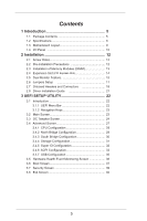
Expansion Slot (PCI Express Slot 14 2.5 Dual Monitor Feature 15 2.6 Jumpers Setup 17 2.7 Onboard Headers and Connectors 18 2.8 Driver Installation Guide 21 3 UEFI SETUP UTILITY 22 3.1 Introduction 22 3.1.1 UEFI Menu Bar 22 3.1.2 Navigation Keys 23 3.2 Main Screen 23 3.3 OC Tweaker Screen - ASRock T48EM1 | User Manual - Page 4
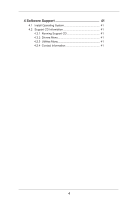
4 Software Support 41 4.1 Install Operating System 41 4.2 Support CD Information 41 4.2.1 Running Support CD 41 4.2.2 Drivers Menu 41 4.2.3 Utilities Menu 41 4.2.4 Contact Information 41 4 - ASRock T48EM1 | User Manual - Page 5
our website for specific information about the model you are using. www.asrock.com/support/index.asp 1.1 Package Contents ASRock T48EM1 Motherboard (Mini-ITX Form Factor) ASRock T48EM1 Quick Installation Guide ASRock T48EM1 Support CD 2 x Serial ATA (SATA) Data Cables (Optional) 1 x I/O Panel Shield - ASRock T48EM1 | User Manual - Page 6
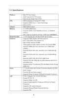
Memory Expansion Slot Graphics Audio LAN - Mini-ITX Form Factor - Solid Capacitor for CPU power - High Density Glass Fabric PCB - AMD Embedded G-Series APU T48E - Supports AMD's Cool 'n' Quiet Technology - UMI 2.5 GT/s - AMD A50M Chipset - 2 x DDR3 DIMM Slots - Supports DDR3 1333/1066/800 non-ECC - ASRock T48EM1 | User Manual - Page 7
Rear Panel I/O - 1 x PS/2 Keyboard/Mouse Port - 1 x D-Sub Port - 1 x DVI-D Port - 1 x HDMI Port - 1 x Optical SPDIF Out Port - 6 x USB 2.0 Ports (Supports ESD Protection (ASRock Full Spike Protection)) - 1 x eSATA3 Connector - 1 x RJ-45 LAN Port with LED (ACT/LINK LED and SPEED LED) - HD - ASRock T48EM1 | User Manual - Page 8
WARNING Please realize that there is a certain risk involved with overclocking, including adjusting the setting in the BIOS, applying Untied Overclocking Technology, or using the third-party overclocking tools. Overclocking may affect your system stability, or even cause damage to the components and - ASRock T48EM1 | User Manual - Page 9
1.3 Motherboard Layout 12 34 5 USB 2.0 T: USB0 B: USB1 PS2 Keyboard/Mouse T48EM1 CHA_FAN1 DDR3 CMOS Battery 6 CLRCMOS1 1 SATA3 6Gb/s DDR3_A1 (64 bit, 240-FpinSBmo8d0ul0e) DDR3_A2 2.0 Header (USB6_7) 20 Front Panel Audio Header (HD_AUDIO1) 21 COM Port Header (COM1) 22 AMD A50M Chipset 9 - ASRock T48EM1 | User Manual - Page 10
1.4 I/O Panel 1 2 34 58 69 7 10 15 14 13 12 11 1 PS/2 Keyboard/Mouse Port (Purple/Green) 9 Front Speaker (Lime)** 2 D-Sub Port 10 Microphone (Pink) 3 USB 2.0 Ports (USB23) 11 USB 2.0 Ports (USB45) 4 LAN RJ-45 Port* 12 eSATA3 Port 5 Central / Bass (Orange) 13 HDMI Port 6 Rear - ASRock T48EM1 | User Manual - Page 11
To enable Multi-Streaming function, you need to connect a front panel audio cable to the front panel audio header. After restarting your computer, you will find "Mixer" tool on your system. Please select "Mixer ToolBox" , click "Enable playback multi-streaming", and click "ok". Choose "2CH", " - ASRock T48EM1 | User Manual - Page 12
Chapter 2: Installation This is a Mini-ITX form factor motherboard. Before you install the motherboard, study the configuration of your chassis to ensure that the motherboard fits into it. Make sure to - ASRock T48EM1 | User Manual - Page 13
2.3 Installation of Memory Modules (DIMM) T48EM1 motherboard provides two 240-pin DDR3 (Double Data Rate 3) DIMM slots. It is not allowed to install a DDR or DDR2 memory module into DDR3 slot; - ASRock T48EM1 | User Manual - Page 14
2.4 Expansion Slot (PCI Express Slot) There is 1 PCI Express slot on this motherboard. PCIE slot: PCIE1 (PCIE x16 slot) is used for PCI Express x4 lane width graphics cards. Installing an expansion card Step 1. Before installing the expansion card, please make sure that the power supply is switched - ASRock T48EM1 | User Manual - Page 15
HDMI monitor cable to HDMI port on the I/O panel. D-Sub port DVI-D port HDMI port 2. If you have installed onboard graphics driver from our support CD to your system already, you can freely enjoy the benefits of dual monitor function after your system boots. If you haven't installed onboard - ASRock T48EM1 | User Manual - Page 16
function with this motherboard, you need to adopt the monitor that supports HDCP function as well. Therefore, you can enjoy the superior display quality with high-definition HDCP encryption contents. Please refer to below instruction for more details about HDCP function. What is HDCP? HDCP stands - ASRock T48EM1 | User Manual - Page 17
, and then shut it down before you do the clear-CMOS ac- tion. Please be noted that the password, date, time, user default profile, 1394 GUID and MAC address will be cleared only if the CMOS battery is removed. 17 - ASRock T48EM1 | User Manual - Page 18
SATA3_2: see p.9, No. 10) (SATA3_3: see p.9, No. 11) (SATA3_4: see p.9, No. 9) SATA3_1 SATA3_2 SATA3_3 SATA3_4 These four Serial ATA3 (SATA3) connectors support SATA data cables for internal storage devices. The current SATA3 interface allows up to 6.0 Gb/s data transfer rate. Serial ATA (SATA - ASRock T48EM1 | User Manual - Page 19
Jack Sensing, but the panel wire on the chassis must support HDA to function correctly. Please follow the instruction in our manual and chassis manual to install your system. 2. If you use AC'97 audio panel, please install it to the front panel audio header as below: A. Connect Mic_IN (MIC) - ASRock T48EM1 | User Manual - Page 20
ATXPWR1) (see p.9 No. 7) 12 24 Please connect the CPU fan cable to the connector and match the black wire to the ground pin. CPU_FAN1 supports fan speed control. Please connect an ATX power supply to this connector. 1 13 Though this motherboard provides 24-pin ATX power connector, 12 24 - ASRock T48EM1 | User Manual - Page 21
2.8 Driver Installation Guide To install the drivers to your system, please insert the support CD to your optical drive first. Then, the drivers compatible to your system can be auto-detected and listed on the support CD driver page. Please follow the order from up to bottom side to install those - ASRock T48EM1 | User Manual - Page 22
SETUP UTILITY when you start up the computer. Please press or during the Power-On-Self-Test (POST) to enter the UEFI SETUP UTILITY, otherwise, POST will continue with its test routines. If you wish to enter the UEFI SETUP UTILITY after POST, restart the system by pressing + - ASRock T48EM1 | User Manual - Page 23
3.1.2 Navigation Keys Please check the following table for the function description of each navigation key. Navigation Key(s) Function Description / Moves cursor left or right to select Screens / Moves cursor up or down to select items + / - To change option for the selected items - ASRock T48EM1 | User Manual - Page 24
out over banks on the same node, or accross nodes, decreasing access contention. CAS# Latency (tCL) Use this item to change CAS# Latency (tCL) Auto/Manual setting. The default is [Auto]. 24 - ASRock T48EM1 | User Manual - Page 25
setting. The default is [Auto]. Four Activate Window (tFAW) Use this item to change Four Activate Window (tFAW) Auto/Manual setting. The default is [Auto]. Voltage Configuration DRAM Voltage Use this to select DRAM Voltage. Configuration options: [Auto], [1.300V] to [1.965V]. The default - ASRock T48EM1 | User Manual - Page 26
+1.8V Voltage Use this to select +1.8V Voltage. Configuration options: [Auto], [1.85V] to [2.10V]. The default value is [Auto]. +1V Voltage Use this to select +1V Voltage. Configuration options: [Auto], [1.07V] to [1.16V]. The default value is [Auto]. User Default In this option, - ASRock T48EM1 | User Manual - Page 27
3.4 Advanced Screen In this section, you may set the configurations for the following items: CPU Configuration, North Bridge Configuration, South Bridge Configuration, Storage Configuration, Super IO Configuration, ACPI Configuration and USB Configuration. Setting wrong values in this section may - ASRock T48EM1 | User Manual - Page 28
Machine) architecture. When this option is set to [Enabled], a VMM (Virtual Machine Architecture) can utilize the additional hardware capabilities provided by AMD-V. Configuration options: [Enabled] and [Disabled]. The default value is [Enabled]. C6 Mode Use this to enable or disable CPU C6 state - ASRock T48EM1 | User Manual - Page 29
3.4.2 North Bridge Configuration Primary Graphics Adapter This item allows you to select the type of Primary VGA in case of multiple video controllers. The default value of this feature is [PCI Express]. Cofiguration options: [Onboard] and [PCI Express]. Share Memory This allows you to set onboard - ASRock T48EM1 | User Manual - Page 30
3.4.3 South Bridge Configuration Onboard HD Audio Select [Auto], [Enabled] or [Disabled] for the onboard HD Audio feature. Front Panel Select [Auto] or [Disabled] for the onboard HD Audio Front Panel. Onboard LAN This allows you to enable or disable the "Onboard LAN" feature. Restore on AC/Power - ASRock T48EM1 | User Manual - Page 31
Use this to select SATA mode. Configuration options: [IDE Mode] and [AHCI Mode]. The default value is [IDE Mode]. 1. AHCI (Advanced Host Controller Interface) supports NCQ and other new features that will improve SATA disk performance but IDE mode does not have these advantages. 2. AHCI mode is not - ASRock T48EM1 | User Manual - Page 32
3.4.5 Super IO Configuration Serial Port Use this item to enable or disable the onboard serial port. Serial Port Address Use this item to set the address for the onboard serial port. Configuration options: [Auto], [3F8 / IRQ4], [2F8 / IRQ3], [3E8 / IRQ4], [2E8 / IRQ3]. CIR Controller Use this item - ASRock T48EM1 | User Manual - Page 33
RAM Use this item to select whether to auto-detect or disable the Suspend-toRAM feature. Select [Auto] will enable this feature if the OS supports it. Check Ready Bit Use this item to enable or disable the feature Check Ready Bit. ACPI HPET Table Use this item to enable or - ASRock T48EM1 | User Manual - Page 34
CSM Please disable CSM when you enable Fast Boot option. The default value is [Enabled]. 34 - ASRock T48EM1 | User Manual - Page 35
to below descriptions for the details of these four options: [Enabled] - Enables support for legacy USB. [Auto] - Enables legacy support if USB devices are connected. [Disabled] - USB devices are not allowed to use ] - USB devices are allowed to use only under UEFI setup and Windows / Linux OS. 35 - ASRock T48EM1 | User Manual - Page 36
Mode]. The default is value [Full On]. Chassis Fan 1 Setting This allows you to set the chassis fan 1 speed. Configuration options: [Full On] and [Manual Mode]. The default is value [Full On]. Chassis Fan 2 Setting This allows you to set the chassis fan 2 speed. Configuration options: [Full On] and - ASRock T48EM1 | User Manual - Page 37
using an USB flash drive. [Ultra Fast] - There are a few restrictions. 1. Only supports Windows® 8.1 / 8 UEFI operating system. 2. You will not be able to enter BIOS ). 3. If you are using an external graphics card, the VBIOS must support UEFI GOP in order to boot. Boot From Onboard LAN Use this item - ASRock T48EM1 | User Manual - Page 38
Full Screen Logo Use this item to enable or disable OEM Logo. The default value is [Enabled]. AddOn ROM Display Use this option to adjust AddOn ROM Display. If you enable the option "Full Screen Logo" but you want to see the AddOn ROM information when the system boots, please select [Enabled]. - ASRock T48EM1 | User Manual - Page 39
3.7 Security Screen In this section, you may set or change the supervisor/user password for the system. For the user password, you may also clear it. Secure Boot Use this to enable or disable Secure Boot. The default value is [Disabled]. 39 - ASRock T48EM1 | User Manual - Page 40
3.8 Exit Screen Save Changes and Exit When you select this option, it will pop-out the following message, "Save configuration changes and exit setup?" Select [OK] to save the changes and exit the UEFI SETUP UTILITY. Discard Changes and Exit When you select this option, it will pop-out the following - ASRock T48EM1 | User Manual - Page 41
applications software that the motherboard supports. Click on a specific item then follow the installation wizard to install it. 4.2.4 Contact Information If you need to contact ASRock or want to know more about ASRock, welcome to visit ASRock's website at http://www.asrock.com; or you may contact - ASRock T48EM1 | User Manual - Page 42
POST and choose the item "UEFI:xxx" to boot. 4. Start Windows® installation. 5. If you install Windows® 7 64-bit OS, OS will be formatted by GPT (GUID Partition Table). Please install the hotfix file from Microsoft®: http://support.microsoft.com/kb/979903 42
-
 1
1 -
 2
2 -
 3
3 -
 4
4 -
 5
5 -
 6
6 -
 7
7 -
8
-
9
-
10
-
11
-
12
-
13
-
14
-
15
-
16
-
17
-
18
-
19
-
20
-
21
-
22
-
23
-
24
-
25
-
26
-
27
-
28
-
29
-
30
-
31
-
32
-
33
-
34
-
35
-
36
-
37
-
38
-
39
-
40
-
41
-
42
 |
 |

1
T48EM1
User Manual
Version 1.0
Published April 2014
Copyright©2014 ASRock INC. All rights reserved.