ASRock X299 OC Formula User Manual
ASRock X299 OC Formula Manual
 |
View all ASRock X299 OC Formula manuals
Add to My Manuals
Save this manual to your list of manuals |
ASRock X299 OC Formula manual content summary:
- ASRock X299 OC Formula | User Manual - Page 1
- ASRock X299 OC Formula | User Manual - Page 2
documentation are furnished for informational use only and subject to change without notice, and should not be constructed as a commitment by ASRock. ASRock assumes no responsibility for any errors or omissions that may appear in this documentation. With respect to the contents of this documentation - ASRock X299 OC Formula | User Manual - Page 3
replaced if the goods fail to be of acceptable quality and the failure does not amount to a major failure. If you require assistance please call ASRock Tel : +886-2-28965588 ext.123 (Standard International call charges apply) - ASRock X299 OC Formula | User Manual - Page 4
26 2.8 Smart Switches 32 2.9 Dr. Debug 35 2.10 Post Status Checker 37 2.11 SLITM , 3-Way SLITM , 4-Way SLITM and Quad SLITM Operation Guide 38 2.11.1 Installing Two SLITM-Ready Graphics Cards 38 2.11.2 Installing Three SLITM-Ready Graphics Cards 40 2.11.3 Installing Four SLITM-Ready - ASRock X299 OC Formula | User Manual - Page 5
M.2_SSD (NGFF) Module Installation Guide 50 Chapter 3 Software and Utilities Operation 54 3.1 Installing Drivers 54 3.2 Formula Drive 55 3.3 ASRock Live Update & APP Shop 58 3.3.1 UI Overview 58 3.3.2 Apps 59 3.3.3 BIOS & Drivers 62 3.3.4 Setting 63 3.4 ASRock RGB LED 64 Chapter - ASRock X299 OC Formula | User Manual - Page 6
4.6 Advanced Screen 85 4.6.1 CPU Configuration 86 4.6.2 Chipset Configuration 88 4.6.3 Storage Configuration 90 4.6.4 Intel® Thunderbolt™ 92 4.6.5 Super IO Configuration 93 4.6.6 ACPI Configuration 94 4.6.7 USB Configuration 95 4.6.8 Trusted Computing 96 4.7 Tools 97 4.8 Hardware - ASRock X299 OC Formula | User Manual - Page 7
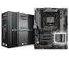
VGA cards and CPU support list on ASRock's website as well. ASRock website http://www.asrock.com. 1.1 Package Contents • ASRock X299 OC Formula Motherboard (ATX Form Factor) • ASRock X299 OC Formula Quick Installation Guide • ASRock X299 OC Formula Support CD • 1 x I/O Panel Shield • 4 x Serial - ASRock X299 OC Formula | User Manual - Page 8
Family for the LGA 2066 Socket • Digi Power design • 13 Power Phase design • Supports Intel® Turbo Boost Max Technology 3.0 * Please note that the 4-Core processors only support Intel® Turbo Boost Technology 2.0. • Supports ASRock Hyper BCLK Engine III Chipset • Intel® X299 Memory • Quad Channel - ASRock X299 OC Formula | User Manual - Page 9
X299 OC Formula Audio LAN * Please note that the 3-Way SLITM configuration varies depending on processor type. * Supports support • Supports Surge Protection (ASRock Full Spike Protection) • Supports Supports DTS Connect • Gigabit LAN 10/100/1000 Mb/s • 1 x Giga PHY Intel® I219V, 1 x GigaLAN Intel - ASRock X299 OC Formula | User Manual - Page 10
ASM1061, support NCQ, AHCI and Hot Plug • 2 x Ultra M.2 Sockets (M2_1 and M2_2), support M Key type 2242/2260/2280/22110 M.2 SATA3 6.0 Gb/s module and M.2 PCI Express module up to Gen3 x4 (32 Gb/s)** ** Supports Intel® OptaneTM Technology ** Supports NVMe SSD as boot disks ** Supports ASRock U.2 Kit - ASRock X299 OC Formula | User Manual - Page 11
X299 OC Formula Connector • 1 x Virtual RAID On CPU Header • 1 x TPM Header • 1 x Power LED and Speaker Header • 2 x RGB LED Headers * Supports in total up to 12V/3A, 36W LED Strip • 1 x Voltage Control Header • 1 x CPU Fan Connector (4-pin) * The CPU Fan Connector supports the CPU fan of maximum - ASRock X299 OC Formula | User Manual - Page 12
to adjust OC frequency • 1 x Menu Button • 1 x PCIe ON/OFF Switch • 1 x Post Status Checker (PSC) • 1 x Slow Mode Switch • 1 x LN2 Mode Switch • 1 x BIOS B Select Jumper BIOS Feature • 2 x AMI UEFI Legal BIOS with multilingual GUI support (1 x Main BIOS and 1 x Backup BIOS) • Supports Secure - ASRock X299 OC Formula | User Manual - Page 13
X299 OC Formula Certifications • FCC, CE • ErP/EuP ready (ErP/EuP ready power supply is required) * For detailed product information, please visit our website: http://www.asrock.com Please realize that there is a certain risk involved with overclocking, including adjusting the setting in the BIOS - ASRock X299 OC Formula | User Manual - Page 14
VGA BOOT USB 2.0 T: USB1 B: USB2 PS2 Keyboard /Mouse BIOS _FB1 CLRC BTN1 USB 3.1 Gen1 T: USB1 B: USB2 USB (64 bit, 288-pin module) ATX12V1 ATX12V2 2066 Socket DDR4_C1 (64 bit, 288-pin module) DDR4_D1 M.2 PCIe Gen3 x4 SATA3_0_1 Intel 25 X299 26 SATA3_2_3 SATA3_4_5 PCIE5 PCIE6 - ASRock X299 OC Formula | User Manual - Page 15
X299 OC Formula No. Description 1 2 x 288-pin DDR4 DIMM Slots (DDR4_B1, DDR4_A1) 2 8 pin 12V Power Connector (ATX12V1) 3 4 pin 12V Power Connector (ATX12V2) 4 PCIe ON/OFF Switch (SWITCH1) 5 2 x 288-pin DDR4 DIMM Slots (DDR4_C1, DDR4_D1) 6 Rapid OC BIOS B Select Jumper (F_BIOS_B1) 33 USB 2.0 Header - ASRock X299 OC Formula | User Manual - Page 16
No. Description 34 USB 2.0 Header (USB5_6) 35 TPM Header (TPMS1) 36 Voltage Control Header (V_CTRL1) 37 Thunderbolt AIC Header (TB1) 38 RGB LED Header (RGB_LED1) 39 Clear CMOS Jumper (CLRMOS1) 40 Right Angle Front Panel Audio Header (HD_AUDIO_RA1) 41 Front Panel Audio Header (HD_AUDIO1) 42 Chassis - ASRock X299 OC Formula | User Manual - Page 17
X299 OC Formula 46 2 3 57 16 15 14 13 12 10 98 11 No. Description 1 USB 2.0 Ports (USB12) 2 LAN RJ-45 Port (Intel® I211AT)* 3 LAN RJ-45 Port (Intel )*** 13 USB 3.1 Gen1 Ports (USB3_12) 14 Clear CMOS Button 15 BIOS Flashback Button 16 PS/2 Mouse/Keyboard Port (PS2_KB1) * There are two - ASRock X299 OC Formula | User Manual - Page 18
Speaker, Central/Bass, and Front Speaker, or select "Realtek HDA Audio 2nd output" to use the front panel audio. *** ACPI wake-up function is not supported on USB3_34 ports. English 12 - ASRock X299 OC Formula | User Manual - Page 19
X299 OC Formula Chapter 2 Installation This is an ATX form factor motherboard. Before you install the motherboard, study the configuration of your chassis to ensure that the motherboard - ASRock X299 OC Formula | User Manual - Page 20
situation is found. Otherwise, the CPU will be seriously damaged. 2. Unplug all power cables before installing the CPU. CAUTION: Please note that X299 platform is only compatible with the LGA 2066 socket, which is incompatible with the LGA 2011-3 socket (for X99 platform). 1 A B A 2 B 14 English - ASRock X299 OC Formula | User Manual - Page 21
X299 OC Formula A 3 B 4 5 15 English - ASRock X299 OC Formula | User Manual - Page 22
6 7 A B 8 A B English Please save and replace the cover if the processor is removed. The cover must be placed if you wish to return the motherboard for after service. 16 - ASRock X299 OC Formula | User Manual - Page 23
2.2 Installing the CPU Fan and Heatsink 9 X299 OC Formula 10 11 CPU_FAN English 17 - ASRock X299 OC Formula | User Manual - Page 24
2.3 Installing the Motherboard Backplate 1 2 18 English - ASRock X299 OC Formula | User Manual - Page 25
X299 OC Formula 3 4 19 English - ASRock X299 OC Formula | User Manual - Page 26
2.4 Installation of Memory Modules (DIMM) This motherboard provides four 288-pin DDR4 (Double Data Rate 4) DIMM slots, and supports Dual Channel Memory Technology. 1. For dual channel configuration, you always need to install identical (the same brand, speed, size and chip-type) DDR4 DIMM pairs. 2. - ASRock X299 OC Formula | User Manual - Page 27
X299 OC Formula 1 2 3 21 English - ASRock X299 OC Formula | User Manual - Page 28
used for PCI Express x8 lane width graphics cards. * 4-Way CrossFireXTM is only supported with CPU with 44 lanes or 28 lanes. * 3-Way SLITM is only supported with CPU with 44 lanes or 28 lanes; 4-Way SLITM is only supported with CPU with 44 lanes. * If you install CPU with 28 lanes or - ASRock X299 OC Formula | User Manual - Page 29
X299 OC Formula PCIe Slot Configurations (For CPU with 28 PCIe lanes) PCIE1 PCIE3 PCIE4 Single Graphics Card x16 N/A N/A PCIE5 N/A PCIE7 N/A Two Graphics Cards in CrossFireXTM or SLITM - ASRock X299 OC Formula | User Manual - Page 30
and pin3 on CLRMOS1 for 5 seconds. However, please do not clear the CMOS right after you update the BIOS. If you need to clear the CMOS when you just finish updating the BIOS, you must boot up the system first, and then shut it down before you do the clear-CMOS action - ASRock X299 OC Formula | User Manual - Page 31
X299 OC Formula BIOS B Select Jumper (F_BIOS_B1) (see p.8, No. 32) 2-pin Jumper Short: Boot from BIOS B Open: Default This motherboard has two BIOS chips, a primary BIOS (BIOS_A1) and a backup BIOS (BIOS_B1), which enhances the safety and stability of your system. Normally, the system will work - ASRock X299 OC Formula | User Manual - Page 32
2.7 Onboard Headers and Connectors Onboard headers and connectors are NOT jumpers. Do NOT place jumper caps over these headers and connectors. Placing jumper caps over the headers and connectors will cause permanent damage to the motherboard. System Panel Header (9-pin PANEL1) (see p.8, No. 29) - ASRock X299 OC Formula | User Manual - Page 33
X299 OC Formula Power LED and Speaker Header (7-pin SPK_PLED1) (see p.8, No. 31) SPEAKER DUMMY DUMMY These eight SATA3 connectors support SATA data cables for internal storage devices with up to 6.0 Gb/s data transfer rate. * To minimize the boot time, use Intel® X299 SATA ports (SATA3_0~5) - ASRock X299 OC Formula | User Manual - Page 34
audio device to either one of the audio connectors. 1. High Definition Audio supports Jack Sensing, but the panel wire on the chassis must support HDA to function correctly. Please follow the instructions in our manual and chassis manual to install your system. 2. If you use an AC'97 audio panel - ASRock X299 OC Formula | User Manual - Page 35
X299 OC Formula Chassis Optional/Water Pump Fan Connector (4-pin CHA_FAN3/W_ PUMP) (see p.8, No. 30) 4 3 21 FAN_SPEED_CONTROL CHA_FAN_SPEED FAN_VOLTAGE GND This motherboard provides a 4-Pin water cooling chassis - ASRock X299 OC Formula | User Manual - Page 36
a 6-pin Graphics 12V power connector. * Install the PSU's power cable to this connector when 4 graphics cards are installed. This connector supports Trusted Platform Module (TPM) system, which can securely store keys, digital certificates, passwords, and data. A TPM system also helps enhance - ASRock X299 OC Formula | User Manual - Page 37
X299 OC Formula RGB LED Headers (4-pin RGB_LED1) (see p.8, No. 38) (4-pin RGB_LED2) (see p.8, to page 64 for further instructions on these two headers. Virtual RAID On CPU Header (4-pin VROC1) (see p.8, No. 19) VROC RAID KEY GND +3VSB GND 1 This connector supports Intel® Virtual RAID on CPU and - ASRock X299 OC Formula | User Manual - Page 38
has twelve smart switches: Power Button, Reset Button, Retry Button, Safe Boot Button, Clear CMOS Button, Rapid OC Buttons, Menu Button, PCIe ON/OFF Switch, Slow Mode Switch, LN2 Mode Switch and BIOS Flashback Button. Power Button (PWR) (see p.8, No. 12) Power Power Button allows users to quickly - ASRock X299 OC Formula | User Manual - Page 39
X299 OC Formula + / - Rapid OC Buttons + + / - Rapid OC Buttons allow users to quickly and easily (PLUS: see p.8, No. 6) (MINUS: see p.8, No. 11) - adjust OC frequency in Rapid OC. This overclocking behavior depends on the system configuration, such as memory capability, thermal solution, etc - ASRock X299 OC Formula | User Manual - Page 40
Flashback Button allows users to flash the BIOS. To use USB BIOS Flashback function, press the BIOS Flashback Button for three seconds. Please follow the steps below. 1. Download the latest BIOS file from ASRock's website : http://www.asrock.com. 2. Copy the BIOS file to your USB flash drive.Please - ASRock X299 OC Formula | User Manual - Page 41
X299 OC Formula 2.9 Dr. Debug Dr. Debug is used to provide code information, which makes troubleshooting even easier. Please see the diagrams below for reading the Dr. Debug codes. Code Description 00 Please check if the CPU is installed correctly and then clear CMOS. 0d Problem related to - ASRock X299 OC Formula | User Manual - Page 42
or try using other memory modules. d6 The VGA could not be recognized. Please clear CMOS and try re-installing the VGA card. If the problem still exists, please try installing the VGA card in other slots or use other VGA cards. d7 The Keyboard and mouse could not be recognized - ASRock X299 OC Formula | User Manual - Page 43
X299 OC Formula 2.10 Post Status Checker Post Status Checker (PSC) diagnoses the computer when users power on the machine. It emits a red light to indicate whether the CPU, memory, VGA or storage is dysfunctional. The lights go off if the four mentioned above are functioning normally. 37 English - ASRock X299 OC Formula | User Manual - Page 44
Guide This motherboard supports NVIDIA® SLITM , 3-way SLITM, 4-way SLITM and Quad SLITM (Scalable Link Interface) technology that allows you to install up to four identical PCI Express x16 graphics cards. * 3-Way SLITM is only supported driver supports NVIDIA® SLITM technology. Download the drivers - ASRock X299 OC Formula | User Manual - Page 45
X299 OC Formula Step 3 Align and insert the ASRock SLI_HB_ Bridge_3S Card (if you install NVIDIA® high-bandwidth graphics cards) to the goldfingers on each graphics card. Make sure the ASRock SLI_HB_Bridge_3S Card is firmly in place. SLI_HB_Bridge_3S Card ASRock SLI_HB_Bridge_3S Card (For NVIDIA® - ASRock X299 OC Formula | User Manual - Page 46
PCI Express graphics card are connected. Repeat this step on the three graphics cards. Step 3 For CPU with 44 PCIe lanes: Align and insert the ASRock 3-Way SLI3S1S Bridge Card to the goldfingers on each graphics card. Make sure the - ASRock X299 OC Formula | User Manual - Page 47
3-Way SLI3S1S 3-Way SLI Bridge X299 OC Formula 3-Way SLI-3S1S Bridge Card (For CPU with 44 PCIe lanes) For CPU with 28 PCIe lanes: Align and insert the ASRock 3-Way SLI Bridge Card to the goldfingers on each graphics card. Make sure the ASRock 3-Way SLI Bridge Card is firmly in place. 3-Way SLI - ASRock X299 OC Formula | User Manual - Page 48
connected. Repeat this step on the three graphics cards. Step 3 Align and insert the ASRock 4-Way SLI-S111 Bridge Card to the goldfingers on each graphics card. Make sure the ASRock 4-Way SLI-S111 Bridge Card is firmly in place. ASRock 4-Way SLI-S111 Bridge Card 42 4-Way SLI Bridge Card English - ASRock X299 OC Formula | User Manual - Page 49
X299 OC Formula Step 4 Connect a VGA cable or a DVI cable to the monitor connector or the DVI connector of the graphics card that is inserted to PCIE1 slot. *If possible, please plug the PSU's power cable to GFX_12V1. 43 English - ASRock X299 OC Formula | User Manual - Page 50
Installation and Setup Install the graphics card drivers to your system. After that, you can enable the Multi-Graphics Processing Unit (GPU) in the NVIDIA® nView system tray utility. Please follow the below - ASRock X299 OC Formula | User Manual - Page 51
X299 OC Formula 2.12 CrossFireXTM, 3-Way CrossFireXTM, 4-Way CrossFireXTM and Quad CrossFireXTM Operation Guide This motherboard supports that your graphics card driver supports AMD CrossFireXTM technology. Download the drivers from the AMD's graphics card manuals for detailed installation guide. 2.12 - ASRock X299 OC Formula | User Manual - Page 52
Step 3 Connect a VGA cable or a DVI cable to the monitor connector or the DVI connector of the graphics card that is inserted to PCIE1 slot. 2.12.2 Installing Three CrossFireXTM-Ready Graphics Cards Step 1 For CPU with 44/16 PCIe lanes: Insert one graphics card into PCIE1 slot, another graphics - ASRock X299 OC Formula | User Manual - Page 53
X299 OC Formula Step 3 Connect a VGA cable or a DVI cable to the monitor connector or the DVI connector of the graphics card that is inserted to PCIE1 slot. *If possible, please plug the PSU's power cable to GFX_12V1. 47 English - ASRock X299 OC Formula | User Manual - Page 54
2.12.3 Installing Four CrossFireXTM-Ready Graphics Cards Step 1 Insert one graphics card into PCIE1 slot, another graphics card into PCIE3 slot, the third graphics card into PCIE5 slot and the last graphics card into PCIE7 slot. Make sure that the cards are properly seated on the slots. CrossFire - ASRock X299 OC Formula | User Manual - Page 55
X299 OC Formula 2.12.4 Driver Installation and Setup Step 1 Power on your computer and boot into OS. Step 2 Remove the AMD drivers if you have any VGA drivers installed in your system. The Catalyst Uninstaller is an optional download. We recommend using this utility to uninstall any previously - ASRock X299 OC Formula | User Manual - Page 56
2.13 M.2_SSD (NGFF) Module Installation Guide The M.2, also known as the Next Generation Form Factor (NGFF), is a small size and versatile card edge connector that aims to replace mPCIe and mSATA. The Ultra M.2 Sockets (M2_1 and M2_2) support SATA3 6.0 Gb/s module and M.2 PCI Express module up to - ASRock X299 OC Formula | User Manual - Page 57
D C B A D C B A B A D C B A D C NUT2 NUT1 X299 OC Formula Step 3 Move the standoff based on the module type and length. The standoff is placed at the nut location D by default. Skip Step 3 and 4 and - ASRock X299 OC Formula | User Manual - Page 58
M.2_SSD (NGFF) Module Support List Vendor ADATA ADATA ADATA ADATA ADATA ADATA ADATA ADATA ADATA Apacer Corsair Crucial Crucial Intel Intel Intel Kingston Kingston Kingston OCZ PATRIOT Plextor Plextor Plextor Plextor Plextor Plextor Samsung Samsung Samsung Samsung Samsung Samsung Samsung Samsung - ASRock X299 OC Formula | User Manual - Page 59
X299 OC Formula TEAM Transcend Transcend Transcend V-Color V-Color V-Color V-Color WD WD WD WD PCIe3 x4 SATA3 WDS256G1X0C-00ENX0 (NVME) WDS512G1X0C-00ENX0 (NVME) For the latest updates of M.2_SSD (NFGG) module support list, please visit our website for details: http://www.asrock.com English 53 - ASRock X299 OC Formula | User Manual - Page 60
not appear automatically, locate and double click on the file "ASRSETUP.EXE" in the Support CD to display the menu. Drivers Menu The drivers compatible to your system will be auto-detected and listed on the support CD driver page. Please click Install All or follow the order from top to bottom to - ASRock X299 OC Formula | User Manual - Page 61
X299 OC Formula 3.2 Formula Drive Formula Drive is ASRock's multi purpose software suite with a new interface, more new features and improved utilities. 3.2.1 Installing Formula Drive Formula Drive can be downloaded from ASRock Live Update & APP Shop. After the installation, you will find the - ASRock X299 OC Formula | User Manual - Page 62
OC Tweaker Configurations for overclocking the system. System Info View information about the system. *The System Browser tab may not appear for certain models. 56 English - ASRock X299 OC Formula | User Manual - Page 63
X299 OC Formula FAN-Tastic Tuning Configure up to five different fan speeds using the graph. The fans will automatically shift to the next speed level when the assigned temperature is met. Settings Configure ASRock Formula Drive. Click to select "Auto run at Windows Startup" if you want Formula - ASRock X299 OC Formula | User Manual - Page 64
Live Update & APP Shop is an online store for purchasing and downloading software applications for your ASRock computer. You can quickly and easily install various apps and support utilities. With ASRock APP Shop, you can optimize your system and keep your motherboard up to date simply with a few - ASRock X299 OC Formula | User Manual - Page 65
X299 OC Formula 3.3.2 Apps When the "Apps" tab is selected, you will see all the available apps on up and down to see more apps listed. You can check the price of the app and whether you have already intalled it or not. - The red icon displays the price or "Free" if the app is free of charge. - The - ASRock X299 OC Formula | User Manual - Page 66
Step 3 If you want to install the app, click on the red icon to start downloading. Step 4 When installation completes, you can find the green "Installed" icon appears on the upper right corner. English To uninstall it, simply click on the trash can icon . *The trash icon may not appear for - ASRock X299 OC Formula | User Manual - Page 67
X299 OC Formula Upgrading an App You can only upgrade the apps you have already installed. When there is an available new version for your app, you will - ASRock X299 OC Formula | User Manual - Page 68
" tab is selected, you will see a list of recommended or critical updates for the BIOS or drivers. Please update them all soon. Step 1 Please check the item information before update. Click on Step 2 to see more details. Click to select one or - ASRock X299 OC Formula | User Manual - Page 69
X299 OC Formula 3.3.4 Setting In the "Setting" page, you can change the language, select the server location, and determine if you want to automatically run the ASRock Live Update & APP Shop on Windows startup. 63 English - ASRock X299 OC Formula | User Manual - Page 70
RGB LED ASRock RGB LED is a lighting control utility specifically designed for unique individuals with that the RGB LED strips do not come with the package. 2. The RGB LED header supports standard 5050 RGB LED strip (12V/G/R/B), with a maximum power rating of 3A (12V) and length within 2 meters. - ASRock X299 OC Formula | User Manual - Page 71
X299 OC Formula ASRock RGB LED Utility Now you can adjust the RGB LED color through the ASRock RGB LED utility. Download this utility from the ASRock Live Update & APP Shop and start coloring your PC style your way! Drag the tab to customize your preference. Toggle on/off the RGB LED - ASRock X299 OC Formula | User Manual - Page 72
may run the UEFI SETUP UTILITY by pressing or right after you power on the computer, otherwise, the Power-On-Self-Test (POST) will continue with its test routines. If you wish to enter the UEFI SETUP UTILITY after POST, restart the system by pressing + + , or by - ASRock X299 OC Formula | User Manual - Page 73
X299 OC Formula 4.2 EZ Mode The EZ Mode screen appears when you enter the BIOS setup program by default. EZ mode is a dashboard which contains multiple readings of the system's current status. You can check the most crucial information of - ASRock X299 OC Formula | User Manual - Page 74
Mode The Advanced Mode provides more options to configure the BIOS settings. Refer to the following sections for the detailed the following selections: Main For setting system time/date information OC Tweaker For overclocking configurations Advanced For advanced system configurations Tool - ASRock X299 OC Formula | User Manual - Page 75
X299 OC Formula 4.3.2 Navigation Keys Use < > key or < > key to choose among the selections on the menu bar, and use < > key or < > key to move the cursor up - ASRock X299 OC Formula | User Manual - Page 76
4.4 Main Screen When you enter the UEFI SETUP UTILITY, the Main screen will appear and display the system overview. Favorite Display your collection of BIOS items. Press F5 to add/remove your favorite items. 70 English - ASRock X299 OC Formula | User Manual - Page 77
you can set up overclocking features. X299 OC Formula Because the UEFI software is constantly being updated, the following UEFI setup screens and descriptions are for reference purpose only, and they may not exactly match what you see on your screen. Load Optimized CPU OC Setting You can use this - ASRock X299 OC Formula | User Manual - Page 78
Use this item to set the maximum OC Ratio for the CPU Mesh. CPU Mesh Min Ratio Use this item to set the minimum OC Ratio for the CPU Mesh. Flex Ratio Select the performance state that the BIOS will set before OS handoff. Intel Turbo Boost Technology Intel Turbo Boost Technology enables the processor - ASRock X299 OC Formula | User Manual - Page 79
X299 OC Formula Intel Speed Shift Technology Enable/Disable Intel Speed Shift Technology support. Enabling will expose the CPPC v2 interface to allow for hardware controlled P-states. Intel Turbo Boost Technology 3.0 Intel Turbo Boost Technology 3.0 enables the processor to run above its base - ASRock X299 OC Formula | User Manual - Page 80
AVX2 Negative Offset specifies a negative offset from the Turbo Ratio Limit for AVX2 workloads. AVX3 Negative Offset AVX3 Negative Offset reduces core frequency. The AVX3 Negative Offset specifies a negative offset from the Turbo Ratio Limit for AVX3 workloads. Primary Plane Current Limit Configure - ASRock X299 OC Formula | User Manual - Page 81
X299 OC Formula BCLK will increase the internal CPU clock speed but also affect the clock speed of other components. DRAM Reference Clock Select Auto for optimized settings. - ASRock X299 OC Formula | User Manual - Page 82
RAS to RAS Delay (tRRD) The number of clocks between two rows activated in different banks of the same rank. RAS to RAS Delay (tRRD_L) The number of clocks between two rows activated in different banks of the same rank. Write to Read Delay (tWTR) The number of clocks between the last valid write - ASRock X299 OC Formula | User Manual - Page 83
X299 OC Formula tCCD_WR_L Configure back to back CAS to CAS (i.e. READ to RAED or WRITE to WRITE) from same rank separation parameter. tRRDS The number of clocks - ASRock X299 OC Formula | User Manual - Page 84
tWWDD Use this item to change tWWDD setting. The default is [Auto] Fourth Timing RTL (A1) Configure the round trip latency for channel A1. RTL (A2) Configure the round trip latency for channel A2. RTL (B1) Configure the round trip latency for channel B1. RTL (B2) Configure the round trip latency for - ASRock X299 OC Formula | User Manual - Page 85
X299 OC Formula IOL (C1) Configure the IO latency for channel C1. IOL (C2) Configure the IO latency for channel C2. IOL (D1) Configure the IO latency for - ASRock X299 OC Formula | User Manual - Page 86
ODT PARK (A2) Configure the memory on die termination resistors' PARK for channel A2. ODT PARK (B1) Configure the memory on die termination resistors' PARK for channel B1. ODT PARK (B2) Configure the memory on die termination resistors' PARK for channel B2. ODT PARK (C1) Configure the memory on die - ASRock X299 OC Formula | User Manual - Page 87
X299 OC Formula Write Latency Enhance Training [Enable] Select this item to enable DDR4 on memory Training Error. Memory Test Use this item to enable or disable memory test during normal boot. MemTestLoops Set the number of memory test loops during normal boot. Memory Test On Fast Boot Use this - ASRock X299 OC Formula | User Manual - Page 88
DRAM AB Voltage Configure the voltage for the DRAM AB. VTTM AB Voltage Configure the voltage for the VTTM AB. VPPM CD Voltage Configure the voltage for the VPPM CD. DRAM CD Voltage Configure the voltage for the DRAM CD. VTTM CD Voltage Configure the voltage for the VTTM CD. 1.0 PCH Voltage Configure - ASRock X299 OC Formula | User Manual - Page 89
X299 OC Formula Offset Prefix Sets the offset value as positive or negative. CPU Mesh Voltage Offset Configure the amount of voltage fed to the UNCores of the - ASRock X299 OC Formula | User Manual - Page 90
SVID Support Enable/Disable SVID. Disabling SVID disables input voltage overrides. Save User Default Type a profile name and press enter to save your settings as user default. - ASRock X299 OC Formula | User Manual - Page 91
X299 OC Formula 4.6 Advanced Screen In this section, you may set the configurations for the following items: CPU Configuration, Chipset Configuration, Storage Configuration, Intel 1920 x 1080 if the monitor supports Full HD resolution. If the monitor does not support Full HD resolution, then the - ASRock X299 OC Formula | User Manual - Page 92
Technology Intel Hyper Threading Technology allows multiple threads to run on each core, so that the overall performance on threaded software is improved. Active Processor Cores Select the number of cores to enable in each processor package. CPU C States Support Enable CPU C States Support for - ASRock X299 OC Formula | User Manual - Page 93
X299 OC Formula Intel Virtualization Technology Intel Virtualization Technology allows a platform to run multiple operating systems and applications in independent partitions, so that one computer system can function as multiple virtual systems. Intel Safer Mode Extensions (SMX) Enable/disable the - ASRock X299 OC Formula | User Manual - Page 94
4.6.2 Chipset Configuration Above 4GB MMIO BIOS Assignment Enable/disable above 4GB MemoryMappedIO BIOS assignment. This is disabled automatically when Aperture Size is set to 2048MB. VT-d Intel® Virtualization Technology for Directed I/O helps your virtual machine monitor better utilize hardware by - ASRock X299 OC Formula | User Manual - Page 95
X299 OC Formula PCIE5 Link Speed Select the link speed for PCIE5. PCIE6 Link Speed Select the link speed for PCIE6. PCIE7 Link Speed Select the link speed for PCIE7. PCIE ASPM Support This option enables/disables the ASPM support for all CPU downstream devices. PCH PCIE ASPM Support This option - ASRock X299 OC Formula | User Manual - Page 96
Controller Speed Indicates the maximum speed the SATA controller can support. SATA Mode Selection [AHCI]: Supports new features that improve performance. [RAID]: Combine multiple disk install CPU with 44 lanes or 28 lanes, RSTe does not support PCH PCIe NVME and VROC (Intel® Virtual RAID on CPU) is - ASRock X299 OC Formula | User Manual - Page 97
X299 OC Formula SATA Aggressive Link Power Management SATA Aggressive Link Power Management allows SATA devices to enter a low power state during periods of inactivity to save power. It is only supported by AHCI mode. Hard Disk S.M.A.R.T. S.M.A.R.T stands for Self-Monitoring, Analysis, and Reporting - ASRock X299 OC Formula | User Manual - Page 98
4.6.4 Intel® Thunderbolt™ Intel(R) Thunderbolt Technonogy Enable/Disable the Intel(R) Thunderbolt function. Security Level Allows you to choose a security level for the Thunderbolt ports 92 English - ASRock X299 OC Formula | User Manual - Page 99
4.6.5 Super IO Configuration X299 OC Formula PS2 Y-Cable Enable the PS2 Y-Cable or set this option to Auto. English 93 - ASRock X299 OC Formula | User Manual - Page 100
4.6.6 ACPI Configuration Suspend to RAM Select disable for ACPI suspend type S1. It is recommended to select auto for ACPI S3 power saving. PS/2 Keyboard Power On Allow the system to be waked up by a PS/2 Keyboard. PCIE Devices Power On Allow the system to be waked up by a PCIE device and enable - ASRock X299 OC Formula | User Manual - Page 101
X299 OC Formula Legacy USB Support Enable or disable Legacy OS Support for USB 2.0 devices. If you encounter USB compatibility issues it is recommended to disable legacy USB support. Select UEFI Setup Only to support enabled for the complete USB keyboard legacy support for non-USB aware OSes. * - ASRock X299 OC Formula | User Manual - Page 102
4.6.8 Trusted Computing Security Device Support Enable or disable BIOS support for security device. 96 English - ASRock X299 OC Formula | User Manual - Page 103
4.7 Tools X299 OC Formula RGB LED RGB LED and header allows users to connect LED strip and create their unique PC style easily. UEFI Tech Service Contact ASRock Tech Service if you are having trouble with your PC. Please setup network configuration before using UEFI Tech Service. Easy RAID - ASRock X299 OC Formula | User Manual - Page 104
- DHCP (Auto IP), Auto ASRock Internet Flash downloads and updates the BIOS. However if the active BIOS is corrupted or damaged, after several failed boot attempts, the backup BIOS will take over. For safety issues, users are not able to update the backup BIOS manually. Users may refer to the BIOS - ASRock X299 OC Formula | User Manual - Page 105
X299 OC Formula Network Configuration Use this to configure internet connection settings for Internet Flash. Internet Setting Enable or disable sound effects in the setup utility. UEFI Download Server Select a server to download the UEFI firmware. 99 English - ASRock X299 OC Formula | User Manual - Page 106
4.8 Hardware Health Event Monitoring Screen This section allows you to monitor the status of the hardware on your system, including the parameters of the CPU temperature, motherboard temperature, fan speed and voltage. Fan Tuning Measure Fan Min Duty Cycle. Fan-Tastic Tuning Select a fan mode for - ASRock X299 OC Formula | User Manual - Page 107
X299 OC Formula CPU_OPT / W_Pump Switch Select CPU Optional or Water Pump mode. CPU Optional Fan Control Mode Select PWM mode or DC mode for CPU Optional fan. - ASRock X299 OC Formula | User Manual - Page 108
Chassis Fan 2 Step Up Set the value of Chassis Fan 2 Step Up. Chassis Fan 2 Step Down Set the value of Chassis Fan 2 Step Down. CHA_FAN3 / W_Pump Switch Select CHA_FAN3/CPU Optional or Water Pump mode. Chassis Fan 3 Control Mode Select PWM mode or DC mode for Chassis Fan 3. Chassis Fan 3 Setting - ASRock X299 OC Formula | User Manual - Page 109
X299 OC Formula 4.9 Security Screen In this section you may set or change the remove the password. Secure Boot Use this item to enable or disable support for Windows 8.1 Secure Boot. Intel(R) Platform Trust Technology Enable/disable Intel PTT in ME. Disable this option to use discrete TPM Module. - ASRock X299 OC Formula | User Manual - Page 110
4.10 Boot Screen This section displays the available devices on your system for you to configure the boot settings and the boot priority. Boot From Onboard LAN Allow the system to be waked up by the onboard LAN. Setup Prompt Timeout Configure the number of seconds to wait for the setup hot key. - ASRock X299 OC Formula | User Manual - Page 111
X299 OC Formula Boot Failure Guard Message If the computer fails to boot for a number of times the system automatically restores the default settings. CSM (Compatibility Support Module) CSM Enable to launch the Compatibility Support Module. Please do not disable unless you're running a WHCK test. If - ASRock X299 OC Formula | User Manual - Page 112
4.11 Exit Screen Save Changes and Exit When you select this option the following message, "Save configuration changes and exit setup?" will pop out. Select [OK] to save changes and exit the UEFI SETUP UTILITY. Discard Changes and Exit When you select this option the following message, "Discard - ASRock X299 OC Formula | User Manual - Page 113
or want to know more about ASRock, you're welcome to visit ASRock's website at http://www.asrock.com; or you may contact your dealer for further information. For technical questions, please submit a support request form at http://www.asrock.com/support/tsd.asp ASRock Incorporation 2F., No.37, Sec
-
 1
1 -
 2
2 -
 3
3 -
 4
4 -
 5
5 -
 6
6 -
 7
7 -
8
-
9
-
10
-
11
-
12
-
13
-
14
-
15
-
16
-
17
-
18
-
19
-
20
-
21
-
22
-
23
-
24
-
25
-
26
-
27
-
28
-
29
-
30
-
31
-
32
-
33
-
34
-
35
-
36
-
37
-
38
-
39
-
40
-
41
-
42
-
43
-
44
-
45
-
46
-
47
-
48
-
49
-
50
-
51
-
52
-
53
-
54
-
55
-
56
-
57
-
58
-
59
-
60
-
61
-
62
-
63
-
64
-
65
-
66
-
67
-
68
-
69
-
70
-
71
-
72
-
73
-
74
-
75
-
76
-
77
-
78
-
79
-
80
-
81
-
82
-
83
-
84
-
85
-
86
-
87
-
88
-
89
-
90
-
91
-
92
-
93
-
94
-
95
-
96
-
97
-
98
-
99
-
100
-
101
-
102
-
103
-
104
-
105
-
106
-
107
-
108
-
109
-
110
-
111
-
112
-
113
 |
 |
