ASRock X533 User Manual
ASRock X533 Manual
 |
View all ASRock X533 manuals
Add to My Manuals
Save this manual to your list of manuals |
ASRock X533 manual content summary:
- ASRock X533 | User Manual - Page 1
X533 User Manual Version 1.0 Published April 2003 Copyright©2003 ASRock INC. All rights reserved. 1 - ASRock X533 | User Manual - Page 2
backup purpose, without written consent of ASRock Inc. Products and corporate names appearing in this manual may or may not be registered trademarks benefit, without intent to infringe. Disclaimer: Specifications and information contained in this manual are furnished for informational use only and - ASRock X533 | User Manual - Page 3
Specifications 5 1.3 Motherboard Layout 7 1.4 ASRock 14 3 BIOS Setup 16 3.1 BIOS Setup Utility 16 3.2 BIOS Setup Utility Support 28 4.1 Installing Operating System 28 4.2 Support CD Information 28 4.2.1 Running The Support CD 28 4.2.2 Drivers Menu 28 4.2.3 Utilities Menu 28 4.2.4 ASRock - ASRock X533 | User Manual - Page 4
contain introduction of the motherboard and step-bystep installation guide for new DIY system builders. Chapter 3 and 4 contain basic BIOS setup and Support CD information. Because the motherboard specifications and the BIOS software might be updated, the content of this manual will be subject to - ASRock X533 | User Manual - Page 5
fan tachometer; Chassis fan tachometer PCI slots: 6 slots with PCI Specification 2.2 AGP slot: 1 universal AGP slot, supports 3.3V/1.5V, 4X/2X/1X AGP card USB 2.0: 4 default USB 2.0 ports and a set of header for 2 additional ASRock I/OTM: USB 2.0 ports upgrade (NOTE 3) PS/2: 1 keyboard port - ASRock X533 | User Manual - Page 6
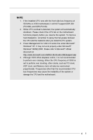
the front side bus frequency at 533 MHz on X533 motherboard, it will NOT support DDR 200 (PC1600), and SDR (PC100). 2. While CPU overheat is detected, the system will automatically shutdown. Please check if the CPU fan on the motherboard functions properly before you resume the system. To improve - ASRock X533 | User Manual - Page 7
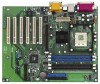
1.3 Motherboard Layout 1 27 2 24.4cm Super I/O 11 2MB BIOS VIA P4X266E Chipset 01 23 01 23 IDE1 IDE2 AGP1 8 7 PCI 1 CMOS Battery 17 CLRCMOS1 PCI 2 VIA VT8235 9 CHA_FAN1 16 SPEAKER1 1 15 PCI 3 PCI 4 PCI 5 1 FSB_SEL0 FLOPPY1 USB45 1 X533 IR1 1 PLED PWRBTN 1 1 PANEL - ASRock X533 | User Manual - Page 8
1.4 ASRock I/OTM 1 2 3 10 9 1 Parallel port 2 RJ-45 port 3 Game port 4 Microphone (Pink) 5 Line In (Light Blue) 8 7 654 6 Line Out (Lime) 7 USB 2.0 ports 8 Serial port: COM1 9 PS/2 keyboard port (Purple) 10 PS/2 mouse port (Green) 8 - ASRock X533 | User Manual - Page 9
2 Installation X533 is an ATX form factor (12.0" x 9.6", 30.5 x 24.4 cm) motherboard. Before you install the motherboard, study the configuration of your chassis to ensure that the motherboard fits into it. Make sure to unplug the power cord before installing or removing the motherboard. Failure to - ASRock X533 | User Manual - Page 10
sure that the CPU and the heatsink are securely fastened and in good contact with each other. For proper installation, please kindly refer to the instruction manuals of vendors of CPU fan and heatsink. 10 - ASRock X533 | User Manual - Page 11
2.5 Installation of Memory Modules (DIMM) SDRAM (Synchronous DRAM) DIMM (Dual In-line Memory Module) has 168 pinsand DDR (Double Data Rate) SDRAM DIMM has 184 pins. Please make sure to disconnect power supply before adding or removing DIMMs or the system components. 168-pin RAM 184-pin RAM The - ASRock X533 | User Manual - Page 12
AGP Slots) There are 6 PCI slots and 1 AGP slot on X533 motherboard. PCI slots: PCI slots are used to install expansion cards that have the 32-bit PCI interface. AGP slot: The AGP slot is used to install a graphics card. The ASRock AGP slot has a special locking mechanism which can securely fasten - ASRock X533 | User Manual - Page 13
(see p.7 item 26) Setting 1_2 FSB_SEL0 FSB 400MHz 2_3 FSB_SEL0 FSB 533MHz Note: The setting of the CPU front side bus frequency of this motherboard is by means of the adjustment of jumper-setting. Please follow the figures above to set the CPU front side bus frequency. PS2_USB_PWR1 (see p.7 item - ASRock X533 | User Manual - Page 14
see p.7 item 8) PIN1 IDE1 PIN1 IDE2 connect the blue end to the motherboard connect the black end to the IDE devices 80-Pin ATA 100/133 USB_PWR P-5 P+5 GND DUMMY 1 GND P+4 P-4 USB_PWR IRTX +5V DUMMY 1 GND IRRX ASRock I/OTM provides you 4 default USB 2.0 ports on the rear panel. If the rear - ASRock X533 | User Manual - Page 15
Internal audio connectors (4-pin CD1, 4-pin AUX1) (CD1: see p.7 item 24) (AUX1: see p.7 item 23) CD-L GND GND CD-R AUX-L GND GND AUX-R CD1 AUX1 These connectors allow you to receive stereo audio input from sound sources such as a CD-ROM, DVD-ROM, TV tuner card, or MPEG card. Front panel audio - ASRock X533 | User Manual - Page 16
updated, the following BIOS setup screens and descriptions are for refer ence purpose only, and may not exactly match what you see on your screen. 3.2 BIOS Setup Utility Main Menu When you enter the BIOS Setup utility, the following screen appears: AMIBIOS SETUP UTILITY - VERSION 3.31a X533 BIOS - ASRock X533 | User Manual - Page 17
IDE Devices Feb 10 2003 Mon 20:07:40 Month: Jan - Dec Day: 01 - 31 Year: 1980 - 2099 BIOS Version Processor Type Processor Speed Cache Size Microcode Update Total Memory DDR1 DDR2 SDR1 SDR2 X533 BIOS P1.00 Pentium (R) 4 Family CPU 2400 MHz 512 KB F24 / 0F 512 MB 512 MB / 266 MHz None - ASRock X533 | User Manual - Page 18
size for the hard disk drive that you configured. [USER]: It allows user to manually enter the number of cylinders, heads, and sectors per track for the drive. , the BIOS Setup may detect incorrect parameters. In these cases, select [User] to manually enter the IDE hard disk drive parameters. 18 - ASRock X533 | User Manual - Page 19
per track. Refer to the drive documentation to determine the correct value. Maximum Capacity This field shows the drive's maximum capacity as calculated by the BIOS based on the drive information you entered. LBA Mode This allows user to select the LBA mode for a hard disk > 512 MB under DOS and - ASRock X533 | User Manual - Page 20
options: [Setup], [Always]. If [Setup] option is selected, the "Password Check" is performed before BIOS setup. If [Always] option is selected, the "Password Check" is performed before both boot-up and BIOS setup. Boot From Network Use this to enable or disable "boot from network" feature. Boot - ASRock X533 | User Manual - Page 21
USB Controller USB Device Legacy Support Disabled Auto 133MHz Locked 266MHz manually. However, this is not recommended unless user thoroughly knows the feature. Wrong setup may cause problems during operation. CPU Ratio Selection This shows current CPU host frequency of the installed motherboard - ASRock X533 | User Manual - Page 22
when using ISA cards that are not PCI 2.1 compliant. USB Controller Use this to enable or disable the use of USB devices. USB Device Legacy Support Use this to enable or disable support to emulate legacy I/O devices such as mouse, keyboard,... etc. 22 - ASRock X533 | User Manual - Page 23
allows you to select whether to auto-detect or disable the ACPI Suspend-to-RAM feature. Select [Auto] will enable this feature if the system supports it. Repost Video on S3 Resume This feature allows you to repost video on S3 resume. It is recommended to enable this feature under Microsoft - ASRock X533 | User Manual - Page 24
F10:Save & Exit PCI Latency Timer (PCI Clocks) The default is 32. We recommend you to keep the default value unless your PCI expansion cards' specifications require other settings. Primary Graphics Adapter Select AGP or PCI as the primary graphics adapter. 24 - ASRock X533 | User Manual - Page 25
3.9 Peripheral Setup AMIBIOS SETUP UTILITY - VERSION 3.31a Peripheral Setup [ Setup Help ] OnBoard FDC OnBoard Serial Port OnBoard Infrared Port OnBoard Parallel Port Parallel Port Mode EPP Version Parallel Port IRQ Parallel Port DMA Channel OnBoard Midi Port Midi IRQ Select OnBoard Game Port - ASRock X533 | User Manual - Page 26
OnBoard IDE Select [Primary] or [Secondary] to enable either the primary IDE channel or the secondary IDE channel. Or you may select [Both] to enable both IDE channels. If it is set to [Disabled], it will disable the both. Configuration options: [Disabled], [Primary], [Secondary], [Both]. OnBoard - ASRock X533 | User Manual - Page 27
to monitor the parameters for CPU temperature, Motherboard temperature, CPU fan speed, and critical voltage optimized defaults for all appropriate items in the BIOS Setup Utility. Press to install the defaults when your hardware does not support them. 3.13 Save Settings and Exit Select - ASRock X533 | User Manual - Page 28
detects installed devices. Install the necessary drivers to activate the devices. 4.2.3 Utilities Menu The Utilities Menu shows the applications software that the motherboard supports. Click on a specific item then follow the installation wizard to install it. 4.2.4 ASRock PC-DIY Live Demo Program
-
 1
1 -
 2
2 -
 3
3 -
 4
4 -
 5
5 -
 6
6 -
 7
7 -
8
-
9
-
10
-
11
-
12
-
13
-
14
-
15
-
16
-
17
-
18
-
19
-
20
-
21
-
22
-
23
-
24
-
25
-
26
-
27
-
28
 |
 |

1
X533
User Manual
Version 1.0
Published April 2003
Copyright©2003 ASRock INC. All rights reserved.