ASRock X58 Extreme User Manual
ASRock X58 Extreme Manual
 |
View all ASRock X58 Extreme manuals
Add to My Manuals
Save this manual to your list of manuals |
ASRock X58 Extreme manual content summary:
- ASRock X58 Extreme | User Manual - Page 1
X58 Extreme User Manual Version 1.1 Published July 2009 Copyright©2009 ASRock INC. All rights reserved. 1 - ASRock X58 Extreme | User Manual - Page 2
change without notice, and should not be constructed as a commitment by ASRock. ASRock assumes no responsibility for any errors or omissions that may appear in this manual. With respect to the contents of this manual, ASRock Lithium battery adopted on this motherboard contains Perchlorate, a toxic - ASRock X58 Extreme | User Manual - Page 3
List 10 1.4 Two CrossFireXTM Graphics Card Support List 11 1.5 Three CrossFireXTM Graphics Card Support List .......... 11 1.6 Motherboard Layout 12 1.7 I/O Panel 13 2 Installation 14 2.1 Screw Holes 14 2.2 Pre-installation Precautions 14 2.3 CPU Installation 15 2.4 Installation of Heatsink - ASRock X58 Extreme | User Manual - Page 4
Windows® VistaTM / VistaTM 64-bit Without RAID Functions 52 2.22 Untied Overclocking Technology 52 3 BIOS SETUP UTILITY 53 3.1 Introduction 53 3.1.1 BIOS Menu Bar 53 Support 74 4.1 Install Operating System 74 4.2 Support CD Information 74 4.2.1 Running Support CD 74 4.2.2 Drivers Menu - ASRock X58 Extreme | User Manual - Page 5
guide to BIOS setup and information of the Support CD. Because the motherboard specifications and the BIOS software might be updated, the content of this manual will be subject to change without notice. In case any modifications of this manual occur, the updated version will be available on ASRock - ASRock X58 Extreme | User Manual - Page 6
CPU Chipset Memory Expansion Slot Audio LAN Rear Panel I/O - ATX Form Factor: 12.0-in x 9.6-in, 30.5 cm x 24.4 cm - All Solid Capacitor design (100% Japan-made high-quality Conductive Polymer Capacitors) - Intel® Socket 1366 CoreTM i7 Processor Extreme Edition / CoreTM i7 Processor Supports - ASRock X58 Extreme | User Manual - Page 7
- ACPI 1.1 Compliance Wake Up Events - Supports jumperfree - SMBIOS 2.3.1 Support - CPU, DRAM, NB, SB, VTT Voltage Multi-adjustment - Supports I. O. T. (Intelligent Overclocking Technology) - Supports Smart BIOS - Drivers, Utilities, AntiVirus Software (Trial Version) - ASRock OC Tuner (see CAUTION - ASRock X58 Extreme | User Manual - Page 8
memory size may be less than 4GB for the reservation for system usage under Windows® XP and Windows® VistaTM. For Windows® XP 64-bit and Windows® VistaTM 64-bit with 64-bit CPU, there is no such limitation. 5. For microphone input, this motherboard supports both stereo and mono modes. For audio - ASRock X58 Extreme | User Manual - Page 9
of Intelligent Energy Saver. ASRock website: http://www.asrock.com 10. ASRock Instant Flash is a BIOS flash utility embedded in Flash ROM. This convenient BIOS update tool allows you to update system BIOS without entering operating systems first like MS-DOS or Windows®. With this utility, you - ASRock X58 Extreme | User Manual - Page 10
1 . 3 Two SLITM Graphics Card Support List (for Windows® XP / XP 64-bit / VistaTM / VistaTM 64-bit) Chipset Vendor NVIDIA Model Name Gigabyte GV-NX88T256H Gigabyte GV-NX88S512H-B LEADTEK PX8800 GTX TDH Chaintech GES96GT-A1512P ASUS EN9800GT TDP/HTDP/512M LEADTEK PX9800GTX LEADTEK PX9800 GTX+ - ASRock X58 Extreme | User Manual - Page 11
://www.asrock.com/support/index.htm 1.5 Three CrossFireXTM Graphics Card Support List (for Windows® VistaTM / VistaTM 64-bit) Chipset Vendor ATI Model Name Gecube GC-HD485PG3-E3 Chipset Name RADEON 4850 Driver Catalyst 9.1 * For the latest updates of the supported PCI Express VGA card list for - ASRock X58 Extreme | User Manual - Page 12
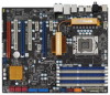
23 22 21 20 19 1 PS2_USB_PWR1 Jumper 20 Debug LED 2 CPU Fan Connector (CPU_FAN1) 21 Reset Switch (RSTBTN) 3 ATX 12V Power Connector (ATX12V1) 22 Power Switch (PWRBTN) 4 1366-Pin CPU Socket 23 Chassis Fan Connector (CHA_FAN1) 5 Power Fan Connector (PWR_FAN1) 24 Clear CMOS Jumper (CLRCMOS1 - ASRock X58 Extreme | User Manual - Page 13
12 ** 10 11 12 13 14 15 16 17 18 Front Speaker (Lime) Microphone (Pink) USB 2.0 Ports (USB67) USB 2.0 Ports (USB45) USB 2.0 Ports (USB23) Powered eSATAII/USB LED indications. LAN Port LED Indications Activity/Link LED SPEED LED Status Description Status Description ACT/LINK SPEED LED LED - ASRock X58 Extreme | User Manual - Page 14
grounded antistatic pad or in the bag that comes with the component. Before you install or remove any component, ensure that the power is switched off or the power cord is detached from the power supply. Failure to do so may cause severe damage to the motherboard, peripherals, and/or components. 14 - ASRock X58 Extreme | User Manual - Page 15
there is any bent pin on the socket. Do not force to insert the CPU into the socket if above situation is found. Otherwise, the CPU will be seriously damaged. Step 1. Open the socket: Step 1-1. Disengaging the the PnP cap. 2. This cap must be placed if returning the motherboard for after service. 15 - ASRock X58 Extreme | User Manual - Page 16
, please ensure to match the two orientation key notches of the CPU with the two alignment keys of the socket. Step 3-3. Carefully place the CPU into the socket by using a purely vertical motion. Step 3-4. Verify that the CPU is within the socket and properly mated to the orient keys. Step - ASRock X58 Extreme | User Manual - Page 17
are securely fastened and in good contact with each other. Then connect the CPU fan to the CPU_FAN connector (CPU_FAN1, see page 12, No. 2). For proper installation, please kindly refer to the instruction manuals of your CPU fan and heatsink. Below is an example to illustrate the installation of - ASRock X58 Extreme | User Manual - Page 18
p.12 No.12), so that Triple Channel Memory Technology can be activated. This motherboard also allows you to install six DDR3 DIMMs for Due to Intel® CPU spec definition, XMP DIMMs and DDR3 2000/ 1866/1600 are supported for one DIMM per channel only. 4. You may install varying memory sizes in Channel - ASRock X58 Extreme | User Manual - Page 19
Installing a DIMM Please make sure to disconnect power supply before adding or removing DIMMs or the system components. The DIMM only fits in one correct orientation. It will cause permanent damage to the motherboard and the DIMM if you force the DIMM into the slot at incorrect orientation. Step - ASRock X58 Extreme | User Manual - Page 20
cards to support CrossFireXTM or SLITM power supply is switched off or the power cord is unplugged. Please read the documentation of the expansion card and make necessary hardware settings for the card before you start the installation. Step 2. Remove the system unit cover (if your motherboard - ASRock X58 Extreme | User Manual - Page 21
. 2. Make sure that your graphics card driver supports NVIDIA® SLITM technology. Download the driver version 181.20 or later from NVIDIA® website (www.nvidia.com). 3. Make sure that your power supply unit (PSU) can provide at least the minimum power required by your system. It is recommended - ASRock X58 Extreme | User Manual - Page 22
Step3. Align and insert ASRock SLI_Bridge_2S Card to the goldfingers on each graphics card. Make sure ASRock SLI_Bridge_2S Card is firmly in place. ASRock SLI_Bridge_2S Card Step4. Connect a VGA cable or a DVI cable to the monitor connector or the DVI connector of the graphics card that is inserted - ASRock X58 Extreme | User Manual - Page 23
Installation and Setup Install the graphics card drivers to your system. After that, you can enable the MultiGraphics Processing Unit (GPU) feature in the NVIDIA® nView system tray utility. Please follow the below procedures to enable the multi-GPU feature. For Windows® XP / XP 64-bit OS: (For SLITM - ASRock X58 Extreme | User Manual - Page 24
® VistaTM / VistaTM 64-bit OS: (For SLITM and Quad SLITM mode) A. Click the Start icon on your Windows taskbar. B. From the pop-up menu, select All Programs, and then click NVIDIA Corporation. C. Select NVIDIA Control Panel tab. D. Select Control Panel tab. E. From the - ASRock X58 Extreme | User Manual - Page 25
Guide This motherboard supports supported with Windows® XP with Service Pack 2 and VistaTM OS. 3-Way CrossFireXTM and Quad CrossFireXTM feature are supported with Windows® VistaTM OS only. Please check AMD website for ATITM CrossFireXTM driver updates card manuals for detailed installation guide. - ASRock X58 Extreme | User Manual - Page 26
Bridge Interconnects on the top of Radeon graphics cards. (CrossFire Bridge is provided with the graphics card you purchase, not bundled with this motherboard. Please refer to your graphics card vendor for details.) CrossFire Bridge or Step 3. Connect the DVI monitor cable to the DVI connector - ASRock X58 Extreme | User Manual - Page 27
connect Radeon graphics cards on PCIE4 and PCIE5 slots. (CrossFire Bridge is provided with the graphics card you purchase, not bundled with this motherboard. Please refer to your graphics card vendor for details.) CrossFire Bridge Step 3. Connect the DVI monitor cable to the DVI connector on the - ASRock X58 Extreme | User Manual - Page 28
to installation. Please check AMD website for ATITM driver updates. Step 3. Step 4. Step 5. Install the required drivers to your system. For Windows® XP OS: A. ATITM recommends Windows® XP Service Pack 2 or higher to be installed (If you have Windows® XP Service Pack 2 or higher installed in your - ASRock X58 Extreme | User Manual - Page 29
for identification or explanation and to the owners' benefit, without intent to infringe. * For further information of ATITM CrossFireXTM technology, please check AMD website for updates and details. 29 - ASRock X58 Extreme | User Manual - Page 30
the system parameters to default setup, please turn off the computer and unplug the power cord from the power supply. After waiting for 15 seconds, use a jumper cap to short pin2 and pin3 on CLRCMOS1 for 5 seconds. However, please do not clear the CMOS right after you update the BIOS. If you need to - ASRock X58 Extreme | User Manual - Page 31
) (39-pin IDE1, see p.12 No. 14) PIN1 IDE1 connect the blue end to the motherboard connect the black end to the IDE devices 80-conductor ATA 66/100/133 cable Note: Please refer to the instruction of your IDE device vendor for the details. Serial ATAII Connectors (SATAII_1_2: see p.12, No - ASRock X58 Extreme | User Manual - Page 32
the white end of SATA power cable to the power connector of the power supply. Besides seven default USB 2.0 ports on the I/O panel, there are two USB 2.0 headers on this motherboard. Each USB 2.0 header can support two USB 2.0 ports. This connector supports a Trusted Platform Module (TPM) system - ASRock X58 Extreme | User Manual - Page 33
cable that allows convenient connection and control of audio devices. 1. High Definition Audio supports Jack Sensing, but the panel wire on the chassis must support HDA to function correctly. Please follow the instruction in our manual and chassis manual to install your system. 2. If you use AC - ASRock X58 Extreme | User Manual - Page 34
function. If you plan to connect the 3-Pin CPU fan to the CPU fan connector on this motherboard, please connect it to Pin 1-3. Pin 1-3 Connected 3-Pin Fan Installation ATX Power Connector (24-pin ATXPWR1) (see p.12, No. 8) 12 24 1 13 Please connect an ATX power supply to this connector. 34 - ASRock X58 Extreme | User Manual - Page 35
Though this motherboard provides 8-pin ATX 12V power connector, it can still work if you adopt a traditional 4-pin ATX 12V power supply. To use the 4-pin ATX power supply, please plug your power supply along with Pin 1 and Pin 5. 8 5 IEEE 1394 Header (9-pin FRONT_1394) (see p.12 No. 10) Serial - ASRock X58 Extreme | User Manual - Page 36
HDMI_SPDIF Cable (Optional) C B A Please connect the black end (A) of HDMI_SPDIF cable to the HDMI_SPDIF header on the motherboard. Then connect the white end (B or C) of HDMI_SPDIF cable to the HDMI_SPDIF connector of HDMI VGA card. A. black end +5V SPDIFOUT GND B. white end (2-pin) C. - ASRock X58 Extreme | User Manual - Page 37
2.12 Quick Switches This motherboard has three quick switches: power switch, reset switch and clear CMOS switch, allowing users to quickly turn on/off or reset the system or clear the CMOS values. Power Switch (PWRBTN) (see p.12 No. 22) Power Switch is a quick switch, allowing users to quickly - ASRock X58 Extreme | User Manual - Page 38
2.13 Debug LED The onboard Debug LED is used to provide code information, which makes troubleshooting even easier. Please see the diagrams below for reading the Debug LED codes. The Bootblock initialization code sets up the chipset, memory and other components before system memory is available. The - ASRock X58 Extreme | User Manual - Page 39
. Verify CMOS checksum manually by reading storage area. If the CMOS checksum is bad, update CMOS with power-on default values and clear passwords. Initialize status register A. Initializes data variables that are based on CMOS setup questions. Initializes both the 8259 compatible PICs in the system - ASRock X58 Extreme | User Manual - Page 40
CPU, etc.) successfully installed in the system and update the BDA, EBDA, etc. 50 Programming the memory hole or any kind of implementation that needs an adjustment in system RAM size if needed. 52 Updates CMOS memory size from memory found in memory test. Allocates memory for Extended BIOS - ASRock X58 Extreme | User Manual - Page 41
compatible digital audio or video monitor, such as a digital television (DTV). A complete HDMI system requires a HDMI VGA card and a HDMI ready motherboard with a HDMI_SPDIF header. This motherboard VGA card. Please refer to the VGA card user manual for connector usage in advance. Connect the HDMI - ASRock X58 Extreme | User Manual - Page 42
guide. Some default setting of SATAII hard disks may not be at SATAII mode, which operate with the best performance. In order to enable SATAII function, please follow the below instruction changing various ATA features. Please visit HITACHI's website for details: http://www.hitachigst.com/hdd/support - ASRock X58 Extreme | User Manual - Page 43
south bridge chipset that supports Serial ATA (SATA) / Serial ATAII (SATAII) hard disks and RAID (RAID 0, RAID 1, RAID 10, RAID 5, and Intel Matrix Storage) functions. You may install SATA / SATAII hard disks on this motherboard for internal storage devices. This section will guide you to install - ASRock X58 Extreme | User Manual - Page 44
motherboard supports Hot Plug and Hot Swap functions for SATA / SATAII in RAID / AHCI mode. Intel® ICH10R south bridge chipset provides hardware support insert and remove the SATA / SATAII HDDs while the system is still power-on and in working condition. However, please note that it cannot perform - ASRock X58 Extreme | User Manual - Page 45
is installed into system properly. The latest SATA / SATAII driver is available on our support website: www.asrock.com 4. Make sure to use the SATA power cable & data cable, which are from our motherboard package. 5. Please follow below instructions step by step to reduce the risk of HDD crash or - ASRock X58 Extreme | User Manual - Page 46
cable 1x4-pin end Step 2 Connect SATA data cable to (White) to the power supply 1x4-pin cable. the motherboard's SATAII connector. SATA power cable 1x4-pin power connector (White) Step 3 Connect SATA 15-pin power cable connector (Black) end to SATA / SATAII HDD. Step 4 Connect SATA data cable - ASRock X58 Extreme | User Manual - Page 47
drive first. Then, the drivers compatible to your system can be auto-detected and listed on the support CD driver page. Please follow the order from up to bottom side to install those required drivers. Therefore, the drivers you install can work properly. 2.20 Installing Windows® XP / XP 64-bit - ASRock X58 Extreme | User Manual - Page 48
the document in the Support CD, "Guide to SATA Hard Disks Installation and RAID Configuration", which is located in the folder at the following path: .. \ RAID Installation Guide STEP 4: Install Windows® XP / XP 64-bit OS on your system. After making a SATA / SATAII driver diskette and using "RAID - ASRock X58 Extreme | User Manual - Page 49
XP or "Intel(R) ICH10R SATA RAID Controller (Desktop - Windows XP64)" for Windows® XP 64-bit. 5. Finish the Windows® installation and install all necessary drivers. 6. Install the Intel(R) Matrix Storage Manager software via the CD-ROM included with your motherboard or after downloading it from the - ASRock X58 Extreme | User Manual - Page 50
drive to boot your system, and follow the instruction to install Windows® VistaTM / VistaTM 64-bit OS on your system. When you see "Where do you want to install Windows?" page, please insert the ASRock Support CD into your optical drive, and click the "Load Driver" button on the left on the bottom - ASRock X58 Extreme | User Manual - Page 51
then in the option "Configure SATAII as", please set the option to [AHCI]. STEP 2: Make a SATA / SATAII driver diskette. Please make a SATA / SATAII driver diskette by following section 2.20.1 step 2 on page 47. STEP 3: Install Windows® XP / XP 64-bit OS on your system. After making a SATA / SATAII - ASRock X58 Extreme | User Manual - Page 52
drive to boot your system, and follow the instruction to install Windows® VistaTM / VistaTM 64-bit OS on your system. When you see "Where do you want to install Windows?" page, please insert the ASRock Support CD into your optical drive, and click the "Load Driver" button on the left on the bottom - ASRock X58 Extreme | User Manual - Page 53
Introduction This section explains how to use the BIOS SETUP UTILITY to configure your system. The BIOS FWH chip on the motherboard stores the BIOS SETUP UTILITY. You may run the BIOS SETUP UTILITY when you start up the computer. Please press during the Power-On-Self-Test (POST) to enter the - ASRock X58 Extreme | User Manual - Page 54
Time System Date [14:00:09] [Mon 07/20/2009] BIOS Version : X58 Extreme P1.00 Processor Type : Intel (R) CPU 000 @ 3.20GHz (64bit) Processor Speed : 3200MHz Microcode Update : 106A4/10 Cache Size : 8192KB Total Memory DDR3_A2 DDR3_A1 DDR3_B2 DDR3_B1 DDR3_C2 DDR3_C1 : 1024MB Single-Channel - ASRock X58 Extreme | User Manual - Page 55
damage to your memory and motherboard. It should be done at your own risk and expense. Overclock Mode Use this to select Overclock Mode. Configuration options: [Auto], [Manual], [I.O.T.] and [Optimized]. The default value is [Auto]. If you select [Manual], Untied Overclocking function is enabled - ASRock X58 Extreme | User Manual - Page 56
CPU Ratio If the ratio status is unlocked, you will find this item appear to allow you changing the ratio value of this motherboard. QPI Frequency Use this option to adjust QPI (QuickPath Interconnect) frequency. Configuration options: [Auto], [4.800GT], [5.866GT] and [6.400GT]. The default value is - ASRock X58 Extreme | User Manual - Page 57
options: [Auto], [2] to [10]. DRAM tRRD This controls the number ASRock VDrop control. Configuration options: [With VDrop] and [Without VDrop]. The default value is [With VDrop]. CPU Voltage Use this to select CPU Voltage. Configuration options: [Auto], [Manual] and [Overdrive Offset]. The default - ASRock X58 Extreme | User Manual - Page 58
Use this to select IOH/ICH PCIE Voltage. Standard: 1.52V. Max: 1.90V. Increment: 0.02V. CPU PLL Voltage Use this to select CPU PLL Voltage. Standard: 1.82V. Max: 2.50V. Increment: 0.02V. Would you like to save current setting user defaults? In this option, you are allowed to load and save three user - ASRock X58 Extreme | User Manual - Page 59
. CPU Configuration Chipset Configuration ACPI Configuration Storage Configuration PCIPnP Configuration Floppy Configuration SuperIO Configuration USB Configuration BIOS Update Utility ASRock Instant Flash Select Screen Select Item Enter Go to Sub Screen F1 General Help F9 Load Defaults F10 - ASRock X58 Extreme | User Manual - Page 60
Megatrends, Inc. CPU Ratio If the ratio status is unlocked, you will find this item appear to allow you changing the ratio value of this motherboard. Enhance Halt State All processors support the Halt State (C1). The C1 state is supported through the native processor instructions HLT and MWAIT - ASRock X58 Extreme | User Manual - Page 61
item to [Enabled]. This item will be hidden if the current CPU does not support Intel (R) SpeedStep(tm) tech.. Please note that enabling this function may reduce CPU voltage and lead to system stability or compatibility issue with some power supplies. Please set this item to [Disable] if above issue - ASRock X58 Extreme | User Manual - Page 62
any C-state it wishes, thus allowing for individual core savings to be maximized. The CPU C-state is determined and entered based on the lowest common denominator of both cores' requests, portraying a single CPU entity to the chipset power management hardware and flows. Thus, software can manage - ASRock X58 Extreme | User Manual - Page 63
Saver is a revolutionary technology that delivers unparalleled power savings. The default value is [Disabled]. Configuration options: [Enabled] and [Disabled]. If you want to enable this function, please set this item to [Enabled]. Besides the BIOS option, you can also choose our Intelligent - ASRock X58 Extreme | User Manual - Page 64
On PS / 2 Keyboard Power On RTC Alarm Power On ACPI HPET Table [Auto] [No] [Enabled] [Power Off] [Disabled] [Disabled] [Disabled] [Disabled] [Disabled] Select auto-detect or disable the STR feature. +F1 F9 F10 ESC Select Screen Select Item Change Option General Help Load Defaults Save and Exit - ASRock X58 Extreme | User Manual - Page 65
item to enable or disable ACPI HPET Table. The default value is [Disabled]. Please set this option to [Enabled] if you plan to use this motherboard to submit Windows® VistaTM certification. 3.4.4IDE Configuration BIOS SETUP UTILITY Advanced IDE Configuration SATAII Configuration Configure SATAII - ASRock X58 Extreme | User Manual - Page 66
"Primary IDE Master" as the example in the following instruction. BIOS SETUP UTILITY Advanced Primary IDE Master Device Vendor Size LBA Mode > 512 MB under DOS and Windows; for Netware and UNIX user, select [Disabled] to disable the LBA/Large mode. Block (Multi-Sector Transfer) The default value of - ASRock X58 Extreme | User Manual - Page 67
capability allows the improved transfer-speed and data-integrity for compatible IDE devices. S.M.A.R.T. Use this item to enable or Configuration options: [0], [5], [10], [15], [20], [25], [30] and [35]. The default value is [35]. 3.4.5PCIPnP Configuration BIOS SETUP UTILITY Advanced Advanced PCI - ASRock X58 Extreme | User Manual - Page 68
configure the type of your floppy drive. BIOS SETUP UTILITY Advanced Floppy Configuration Floppy A [1.44 MB 312"] Select the type of floppy drive connected to the system. +F1 F9 F10 ESC Select Screen Select Item Change Option General Help Load Defaults Save and Exit Exit v02.54 (C) Copyright - ASRock X58 Extreme | User Manual - Page 69
3.4.8USB Configuration BIOS SETUP UTILITY Advanced USB Configuration USB Controller USB 2.0 Support Legacy USB Support [Enabled] [Enabled] [Enabled] To enable or disable the onboard USB controllers. +F1 F9 F10 ESC Select Screen Select Item Change Option General Help Load Defaults Save and Exit - ASRock X58 Extreme | User Manual - Page 70
of the CPU temperature, motherboard temperature, CPU fan speed, chassis fan speed, and the critical voltage. BIOS SETUP UTILITY [Manual mode]. The default is value [Full On]. NB FAN Setting This allows you to set the NB fan speed. Configuration options: [Full On] and [Manual mode]. The default is - ASRock X58 Extreme | User Manual - Page 71
for you to configure the boot settings and the boot priority. BIOS SETUP UTILITY Main OC Tweaker Advanced H/W Monitor Boot Security Exit POST messages. +F1 F9 F10 ESC Select Screen Select Item Change Option General Help Load Defaults Save and Exit Exit v02.54 (C) Copyright 1985-2003, American - ASRock X58 Extreme | User Manual - Page 72
Screen Logo". Configuration options: [Auto], [PCIE2.0 Revolution], [Scenery] and [ASRock]. The default value is [Auto]. Currently, the option [Auto] is set to Aircraft. may set or change the supervisor/user password for the system. For the user password, you may also clear it. BIOS SETUP UTILITY - ASRock X58 Extreme | User Manual - Page 73
Monitor Boot Security Exit Exit Options Save Changes and Exit Discard Changes and Exit Discard Changes Load BIOS Defaults Load Performance Setup Default (IDE/SATA) Load Performance Setup AHCI Mode Load Performance Setup RAID Mode Load Power Saving Setup Default Exit system setup after saving the - ASRock X58 Extreme | User Manual - Page 74
install the necessary drivers to activate the devices. 4.2.3 Utilities Menu The Utilities Menu shows the applications software that the motherboard supports. Click on a specific item then follow the installation wizard to install it. 4.2.4 Contact Information If you need to contact ASRock or want to
-
 1
1 -
 2
2 -
 3
3 -
 4
4 -
 5
5 -
 6
6 -
 7
7 -
8
-
9
-
10
-
11
-
12
-
13
-
14
-
15
-
16
-
17
-
18
-
19
-
20
-
21
-
22
-
23
-
24
-
25
-
26
-
27
-
28
-
29
-
30
-
31
-
32
-
33
-
34
-
35
-
36
-
37
-
38
-
39
-
40
-
41
-
42
-
43
-
44
-
45
-
46
-
47
-
48
-
49
-
50
-
51
-
52
-
53
-
54
-
55
-
56
-
57
-
58
-
59
-
60
-
61
-
62
-
63
-
64
-
65
-
66
-
67
-
68
-
69
-
70
-
71
-
72
-
73
-
74
 |
 |

1
X58 Extreme
User Manual
Version 1.1
Published July 2009
Copyright©2009 ASRock INC. All rights reserved.