ASRock X58 Extreme3 User Manual
ASRock X58 Extreme3 Manual
 |
View all ASRock X58 Extreme3 manuals
Add to My Manuals
Save this manual to your list of manuals |
ASRock X58 Extreme3 manual content summary:
- ASRock X58 Extreme3 | User Manual - Page 1
X58 Extreme3 User Manual Version 1.0 Published February 2010 Copyright©2010 ASRock INC. All rights reserved. 1 - ASRock X58 Extreme3 | User Manual - Page 2
commitment by ASRock. ASRock assumes no responsibility for any errors or omissions that may appear in this manual. With respect to the contents of this manual, ASRock does not , USA ONLY The Lithium battery adopted on this motherboard contains Perchlorate, a toxic substance controlled in Perchlorate - ASRock X58 Extreme3 | User Manual - Page 3
/ SATAII / SATA3 HDD Hot Plug Feature and Operation Guide 46 2.20 Driver Installation Guide 48 2.21 Installing Windows® 7 / 7 64-bit / VistaTM / VistaTM 64-bit / XP / XP 64-bit With RAID Functions 48 2.21.1 Installing Windows® XP / XP 64-bit With RAID Functions 48 2.21.2 Setting Up a "RAID Ready - ASRock X58 Extreme3 | User Manual - Page 4
Windows® 7 / 7 64-bit / VistaTM / VistaTM 64-bit Without RAID Functions 53 2.23 Untied Overclocking Technology 53 3 BIOS SETUP UTILITY 54 3.1 Introduction 54 3.1.1 BIOS Menu Bar 54 3.1.2 Navigation Keys 55 3.2 Main Screen 55 3.3 OC Tweaker Screen 56 3.4 Advanced Screen 60 3.4.1 CPU - ASRock X58 Extreme3 | User Manual - Page 5
guide to BIOS setup and information of the Support CD. Because the motherboard specifications and the BIOS software might be updated, the content of this manual will be subject to change without notice. In case any modifications of this manual occur, the updated version will be available on ASRock - ASRock X58 Extreme3 | User Manual - Page 6
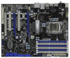
CPU Chipset Memory Expansion Slot Audio LAN Rear Panel I/O - ATX Form Factor: 12.0-in x 9.6-in, 30.5 cm x 24.4 cm - All Solid Capacitor design (100% Japan-made high-quality Conductive Polymer Capacitors) - Intel® Socket 1366 CoreTM i7 Processor Extreme Edition / CoreTM i7 Processor Supports Intel - ASRock X58 Extreme3 | User Manual - Page 7
Intrusion header - 1 x Power LED header - CPU/Chassis/NB/Power FAN connector - 24 pin ATX power connector - 8 pin 12V power connector - CD in header - Front panel audio connector - 2 x USB 2.0 headers (support 4 USB 2.0 ports) (see CAUTION 6) - 1 x Dr. Debug (7-Segment Debug LED) - 1 x Clear CMOS - ASRock X58 Extreme3 | User Manual - Page 8
VCCM, IOH, ICH, VTT, IOH/ICH PCIE, CPU PLL, IOH CSI, VCORE Voltage Multi-adjustment - Supports I. O. T. (Intelligent Overclocking Technology) Support CD - Drivers, Utilities, AntiVirus Software (Trial Version), ASRock Software Suite (CyberLink DVD Suite and Creative Sound Blaster X-Fi MB) (OEM - ASRock X58 Extreme3 | User Manual - Page 9
memory size may be less than 4GB for the reservation for system usage under Windows® 7 / VistaTM / XP. For Windows® OS with 64-bit CPU, there is no such limitation. 5. For microphone input, this motherboard supports both stereo and mono modes. For audio output, this motherboard supports 2-channel - ASRock X58 Extreme3 | User Manual - Page 10
Union to define the power consumption for the completed system. According to EuP, the total AC power of the completed system shall be under 1.00W in off mode condition. To meet EuP standard, an EuP ready motherboard and an EuP ready power supply are required. According to Intel's suggestion, the EuP - ASRock X58 Extreme3 | User Manual - Page 11
Support List (for Windows® XP / XP 64-bit / VistaTM / VistaTM 64-bit / 7 / 7 64-bit) Chipset GV-N26-896H-B Chipset Name Driver GeForce 8800 GT updates of the supported PCI Express VGA card list for SLITM Mode, please visit our website for details. ASRock website: http://www.asrock.com/support/index - ASRock X58 Extreme3 | User Manual - Page 12
Support List (for Windows® VistaTM / VistaTM 64-bit / 7 / 7 64-bit) Chipset Vendor ATI Model Name MSI RX2600PRO-T2D256EZ Gigabyte GV-RX26T256HP-B Powercolor AX3650 512MMD3-XP Gigabyte GV-RX385256H-B Powercolor AX3870 512MD4-H Powercolor AX3870X2 1GBD3-H Gecube GC-HD485PG3-E3 Chipset Name Driver - ASRock X58 Extreme3 | User Manual - Page 13
1 CD1 NB_FAN1 Intel X58 Chipset Top: LINE IN Center: FRONT SATA3_2 SATA3_1 Designed in Taipei LAN PHY AUDIO CODEC Super I/O CI1 1 IR1 1 HDMI_SPDIF1 1 FLOPPY1 NEC USB 3.0 SATA3 6Gb/s IDE1 PCIE1 QPI 6.4GT/s PCIE2 PCI Express 2.0 PCI1 X58 Extreme3 8Mb BIOS 1394a CMOS Battery CLRCMOS1 - ASRock X58 Extreme3 | User Manual - Page 14
Orange) 9 Line In (Light Blue) 14 13 12 ** 10 11 12 13 14 15 16 17 18 Front Speaker (Lime) Microphone (Pink) USB 2.0 Ports (USB23) Powered eSATAIII/USB 2.0 Connector Optical SPDIF Out Port Clear CMOS Switch (CLRCBTN) PS/2 Audio Output Connection Audio Output Channels Front Speaker Rear Speaker Central - ASRock X58 Extreme3 | User Manual - Page 15
-Streaming function, you need to connect a front panel audio cable to the front panel audio header. After restarting your computer, you will find "VIA HD Audio Deck" tool on your system. Please follow below instructions according to the OS you install. For Windows® XP / XP 64-bit OS: Please click - ASRock X58 Extreme3 | User Manual - Page 16
Precautions Take note of the following precautions before you install motherboard components or change any motherboard settings. 1. Unplug the power cord from the wall socket before touching any component. 2. To avoid damaging the motherboard components due to static electricity, NEVER place your - ASRock X58 Extreme3 | User Manual - Page 17
Intel 1366-Pin CPU, please follow the steps below. Load Plate Contact Array Socket Body Load Lever 1366-Pin Socket Overview Before you insert the 1366-Pin CPU into the socket, please check if the CPU surface is unclean or if there is any bent pin on the socket the motherboard for after service. 17 - ASRock X58 Extreme3 | User Manual - Page 18
alignment key orientation key notch 1366-Pin CPU alignment key 1366-Pin Socket For proper inserting, please ensure to match the two orientation key notches of the CPU with the two alignment keys of the socket. Step 3-3. Carefully place the CPU into the socket by using a purely vertical motion - ASRock X58 Extreme3 | User Manual - Page 19
2.4 Installation of CPU Fan and Heatsink This motherboard is equipped with 1366-Pin socket that supports Intel 1366-Pin CPU. Please adopt the type of heatsink and cooling fan compliant with Intel 1366-Pin CPU to dissipate heat. Before you installed the heatsink, you need to spray thermal interface - ASRock X58 Extreme3 | User Manual - Page 20
2. Due to Intel® CPU spec definition, the system will not boot if only one DIMM is installed into DDR3_A2, DDR3_B2 or DDR3_C2 slot. 3. Due to Intel® CPU spec definition, XMP DIMMs and DDR3 2000/ 1866/1600 are supported for one DIMM per channel only. 4. You may install varying memory sizes in Channel - ASRock X58 Extreme3 | User Manual - Page 21
Installing a DIMM Please make sure to disconnect power supply before adding or removing DIMMs or the system break The DIMM only fits in one correct orientation. It will cause permanent damage to the motherboard and the DIMM if you force the DIMM into the slot at incorrect orientation. Step - ASRock X58 Extreme3 | User Manual - Page 22
cards to support CrossFireXTM or SLITM power supply is switched off or the power cord is unplugged. Please read the documentation of the expansion card and make necessary hardware settings for the card before you start the installation. Step 2. Remove the system unit cover (if your motherboard - ASRock X58 Extreme3 | User Manual - Page 23
SLITM and Quad SLITM Operation Guide This motherboard supports NVIDIA® SLITM and Quad SLITM (Scalable Link Interface) technology that allows you to install up to two identical PCI Express x16 graphics cards. Currently, NVIDIA® SLITM technology supports Windows® 7 / 7 64-bit / VistaTM / VistaTM 64 - ASRock X58 Extreme3 | User Manual - Page 24
Step3. Align and insert ASRock SLI_Bridge_2S Card to the goldfingers on each graphics card. Make sure ASRock SLI_Bridge_2S Card is firmly in place. ASRock SLI_Bridge_2S Card Step4. Connect a VGA cable or a DVI cable to the monitor connector or the DVI connector of the graphics card that is inserted - ASRock X58 Extreme3 | User Manual - Page 25
card drivers to your system. After that, you can enable the MultiGraphics Processing Unit (GPU) feature in the NVIDIA® nView system tray utility. Please follow the below procedures to enable the multi-GPU feature. For Windows® XP / XP 64-bit OS: (For SLITM mode only) A. Double-click NVIDIA Settings - ASRock X58 Extreme3 | User Manual - Page 26
OS: (For SLITM and Quad SLITM mode) A. Click the Start icon on your Windows taskbar. B. From the pop-up menu, select All Programs, and then click NVIDIA Corporation tab. E. From the pop-up menu, select Set SLI and PhysX configuration. In Set PhysX GPU acceleration item, please select Enabled. In - ASRock X58 Extreme3 | User Manual - Page 27
Guide This motherboard supports supported with Windows® XP with Service Pack 2 / VistaTM / 7 OS. Quad CrossFireXTM feature are supported with Windows® VistaTM / 7 OS only. Please check AMD website for ATITM CrossFireXTM driver updates graphics card manuals for detailed installation guide. Step 1. - ASRock X58 Extreme3 | User Manual - Page 28
Bridge Interconnects on the top of Radeon graphics cards. (CrossFire Bridge is provided with the graphics card you purchase, not bundled with this motherboard. Please refer to your graphics card vendor for details.) CrossFire Bridge or Step 3. Connect the DVI monitor cable to the DVI connector - ASRock X58 Extreme3 | User Manual - Page 29
for ATITM driver updates. Step 3. Step 4. Step 5. Install the required drivers to your system. For Windows® XP OS: A. ATITM recommends Windows® XP Service Pack 2 or higher to be installed (If you have Windows® XP Service Pack 2 or higher installed in your system, there is no need to download it - ASRock X58 Extreme3 | User Manual - Page 30
Step 6. Double-click "ATI Catalyst Control Center". Click "View", select "CrossFireXTM", and then check the item "Enable CrossFireXTM". Select the option according to the total GPU number on the Radeon graphics cards. Click "Apply". Although you have selected the option "Enable CrossFireTM", the - ASRock X58 Extreme3 | User Manual - Page 31
for identification or explanation and to the owners' benefit, without intent to infringe. * For further information of ATITM CrossFireXTM technology, please check AMD website for updates and details. 31 - ASRock X58 Extreme3 | User Manual - Page 32
cord from the power supply. After waiting for 15 seconds, use a jumper cap to short pin2 and pin3 on CLRCMOS1 for 5 seconds. However, please do not clear the CMOS right after you update the BIOS. If you need to clear the CMOS when you just finish updating the BIOS, you must boot up the system first - ASRock X58 Extreme3 | User Manual - Page 33
end to the motherboard connect the black end to the IDE devices 80-conductor ATA 66/100/133 cable Note: Please refer to the instruction of your IDE These two Serial ATA3 (SATA3) connectors support SATA data cables for internal storage devices. The current SATA3 interface allows up to 6.0 - ASRock X58 Extreme3 | User Manual - Page 34
the white end of SATA power cable to the power connector of the power supply. Besides five default USB 2.0 ports on the I/O panel, there are two USB 2.0 headers on this motherboard. Each USB 2.0 header can support two USB 2.0 ports. This connector supports a Trusted Platform Module (TPM) system - ASRock X58 Extreme3 | User Manual - Page 35
only. You don't need to connect them for AC'97 audio panel. E. Enter BIOS Setup Utility. Enter Advanced Settings, and then select Chipset Configuration. Set the Front Panel Control option from [Auto] to [Enabled]. System Panel Header (9-pin PANEL1) (see p.13 No. 9) PLED+ PLEDPWRBTN# GND 1 DUMMY - ASRock X58 Extreme3 | User Manual - Page 36
to the ground pin. Though this motherboard provides 4-Pin CPU fan (Quiet Fan) support, the 3-Pin CPU fan still can work successfully even without the fan speed control function. If you plan to connect the 3-Pin CPU fan to the CPU fan connector on this motherboard, please connect it to Pin 1-3. Pin - ASRock X58 Extreme3 | User Manual - Page 37
is one IEEE 1394 header (FRONT_1394) on this motherboard. This IEEE 1394 header can support one IEEE 1394 port. This COM1 header supports a serial port module. HDMI_SPDIF Header (3-pin HDMI_SPDIF1) (see p.13 No. 32) 1 GND SPDIFOUT +5V HDMI_SPDIF header, providing SPDIF audio output to HDMI VGA - ASRock X58 Extreme3 | User Manual - Page 38
HDMI_SPDIF Cable (Optional) C B A Please connect the black end (A) of HDMI_SPDIF cable to the HDMI_SPDIF header on the motherboard. Then connect the white end (B or C) of HDMI_SPDIF cable to the HDMI_SPDIF connector of HDMI VGA card. A. black end +5V SPDIFOUT GND B. white end (2-pin) C. - ASRock X58 Extreme3 | User Manual - Page 39
Switches This motherboard has three smart switches: power switch, reset switch and clear CMOS switch, allowing users to quickly turn on/off or reset the system or clear the CMOS values. Power Switch (PWRBTN) (see p.13 No. 24) Power Switch is a smart switch, allowing users to quickly turn on/off - ASRock X58 Extreme3 | User Manual - Page 40
sizing in Bootblock code. Do additional chipset initialization. Re-enable CACHE. Verify that flat mode is enabled. Test base 512KB memory. Adjust policies and cache first 8MB. Set stack. Bootblock code is copied from ROM to lower system memory and control is given to it. BIOS now executes out of - ASRock X58 Extreme3 | User Manual - Page 41
BIOS modules on POST entry and GPNV area. Initialized CMOS as mentioned in the Kernel Variable "wCMOSFlags." Check CMOS diagnostic byte to determine if battery power is OK and CMOS checksum is OK. Verify CMOS checksum manually by reading storage area. If the CMOS checksum is bad, update CMOS - ASRock X58 Extreme3 | User Manual - Page 42
CPU, etc.) successfully installed in the system and update the BDA, EBDA, etc. 50 Programming the memory hole or any kind of implementation that needs an adjustment in system RAM size if needed. 52 Updates CMOS memory size from memory found in memory test. Allocates memory for Extended BIOS - ASRock X58 Extreme3 | User Manual - Page 43
/ video source, such as a set-top box, DVD player, A/V receiver and a compatible digital audio or video monitor, such as a digital television (DTV). A complete HDMI system requires a HDMI VGA card and a HDMI ready motherboard with a HDMI_SPDIF header. This motherboard is equipped with a HDMI_SPDIF - ASRock X58 Extreme3 | User Manual - Page 44
Intel® ICH10R south bridge chipset that supports Serial ATA (SATA) / Serial ATAII (SATAII) hard disks and RAID (RAID 0, RAID 1, RAID 10, RAID 5, and Intel Matrix Storage) functions. You may install SATA / SATAII hard disks on this motherboard for internal storage devices. This section will guide - ASRock X58 Extreme3 | User Manual - Page 45
HDDs while the system is still power-on and in working condition. 2.18 Hot Plug and Hot Swap Functions for SATA3 HDDs This motherboard supports Hot Plug and Hot Swap functions for SATA3 in RAID / AHCI mode. Marvell SE9128 chipset provides hardware support for Advanced Host controller Interface (AHCI - ASRock X58 Extreme3 | User Manual - Page 46
is installed into system properly. The latest SATA / SATAII / SATA3 driver is available on our support website: www.asrock.com 4. Make sure to use the SATA power cable & data cable, which are from our motherboard package. 5. Please follow below instructions step by step to reduce the risk of HDD - ASRock X58 Extreme3 | User Manual - Page 47
below instruction sequence to process the Hot Plug, improper procedure will cause the SATA / SATAII / SATA3 HDD damage and data loss. Step 1 Please connect SATA power cable 1x4-pin end Step 2 Connect SATA data cable to (White) to the power supply 1x4-pin cable. the motherboard's SATAII / SATA3 - ASRock X58 Extreme3 | User Manual - Page 48
"Configure SATAII as", please set the option to [RAID]. STEP 2: Make a SATA / SATAII Driver Diskette. A. Insert the Support CD into your optical drive to boot your system. B. During POST at the beginning of system boot-up, press key, and then a window for boot devices selection appears. Please - ASRock X58 Extreme3 | User Manual - Page 49
how to build an Intel "RAID Ready" system. 1. Assemble the system and attach a single SATA / SATAII hard drive. 2. Set up system BIOS as step 1 of page 48. When done, exit Setup. 3. Make a SATA / SATAII driver diskette as step 2 of page 48. Begin Windows® setup by booting from the installation CD - ASRock X58 Extreme3 | User Manual - Page 50
motherboard or after downloading it from the Internet. This will add the Intel(R) Matrix Storage Console which can be used to manage the RAID configuration. 7. After setting up a "RAID drive when initiating the migration. 2. Boot Windows®, install the Intel(R) Matrix Storage Manager software, if not - ASRock X58 Extreme3 | User Manual - Page 51
the installation of Windows® 7 / 7 64-bit / VistaTM / VistaTM 64-bit OS, if you want to manage RAID functions, you are allowed to use both "RAID Installation Guide" and "Intel Matrix Storage Manager Information" for RAID configuration. Please refer to the document in the Support CD, "Guide to SATA - ASRock X58 Extreme3 | User Manual - Page 52
XP / XP 64-bit Without RAID Functions If you want to install Windows® XP / XP 64-bit OS on your SATA / SATAII HDDs without RAID functions, please follow below steps. Using SATA / SATAII HDDs and eSATA3 devices with NCQ function STEP 1: Set Up BIOS. A. Enter BIOS SETUP UTILITY Advanced screen Storage - ASRock X58 Extreme3 | User Manual - Page 53
Technology This motherboard supports Untied Overclocking Technology, which means during overclocking, FSB enjoys better margin due to fixed PCI / PCIE buses. Before you enable Untied Overclocking function, please enter "Overclock Mode" option of BIOS setup to set the selection from [Auto] to [Manual - ASRock X58 Extreme3 | User Manual - Page 54
has a menu bar with the following selections: Main To set up the system time/date information OC Tweaker To set up overclocking features Advanced To set up the advanced BIOS features H/W Monitor To display current hardware status Boot To set up the default system device to locate and load the - ASRock X58 Extreme3 | User Manual - Page 55
H/W Monitor Boot Security Exit System Overview System Time System Date [14:00:09] [Tue 02/09/2010] BIOS Version : X58 Extreme3 P1.00 Processor Type : Intel (R) CPU 000 @ 3.20GHz (64bit) Processor Speed : 3200MHz Microcode Update : 106A4/10 Cache Size : 8192KB Total Memory DDR3_A2 DDR3_A1 - ASRock X58 Extreme3 | User Manual - Page 56
that overclocing may cause damage to your CPU and motherboard. It should be done at your own risk and expense. Load DDR3 EZ OC Setting You can use this option to load DDR3 EZ overclocking setting. Please note that overclocing may cause damage to your memory and motherboard. It should be done at your - ASRock X58 Extreme3 | User Manual - Page 57
CPU Ratio Setting If the ratio status is unlocked, you will find this item appear to allow you changing the ratio value of this motherboard selected, the motherboard will detect the memory module(s) inserted Timing Control BIOS SETUP UTILITY Advanced DRAM Timing Control Current Setting : 7-7-7- - ASRock X58 Extreme3 | User Manual - Page 58
options: Configuration options: [Auto], [2] to [10]. DRAM tRRD This controls the number of DRAM ASRock VDroop control. Configuration options: [With VDroop] and [Without VDroop]. The default value is [With VDrop]. CPU Voltage Use this to select CPU Voltage. Configuration options: [Auto], [Manual - ASRock X58 Extreme3 | User Manual - Page 59
PCIE Voltage Use this to select IOH/ICH PCIE Voltage. The default value is [Auto]. CPU PLL Voltage Use this to select CPU PLL Voltage. The default value is [Auto]. Would you like to save current setting user defaults? In this option, you are allowed to load and save three user defaults according - ASRock X58 Extreme3 | User Manual - Page 60
Settings Options for CPU WARNING : Setting wrong values in below sections may cause system to malfunction. CPU Configuration Chipset Configuration ACPI Configuration Storage Configuration PCIPnP Configuration Floppy Configuration SuperIO Configuration USB Configuration BIOS Update Utility ASRock - ASRock X58 Extreme3 | User Manual - Page 61
this motherboard. Enhance Halt State All processors support the Halt State (C1). The C1 state is supported through the native processor instructions HLT and MWAIT and requires no hardware support from the chipset. In the C1 power state, the processor maintains the context of the system caches. Intel - ASRock X58 Extreme3 | User Manual - Page 62
and select [Auto], you need to set the "Power Schemes" as "Portable/Laptop" to enable this function. If you install Windows® VistaTM and want to enable this function, please set this item to [Enabled]. This item will be hidden if the current CPU does not support Intel (R) SpeedStep(tm) tech.. Please - ASRock X58 Extreme3 | User Manual - Page 63
appears only when you set the item Intel (R) C-STATE tech. to [Enabled]. Configuration options: [Auto], [C3] and [C6]. The default value is [Auto]. 3.4.2 Chipset Configuration Advanced Chipset Settings BIOS SETUP UTILITY Primary Graphics Adapter Onboard HD Audio Front Panel Onboard Lan Onboard - ASRock X58 Extreme3 | User Manual - Page 64
VT-d Use this to enable or disable Intel® VT-d technology (Intel® Virtualization Technology for Directed I/O). The default value of this feature is [Disabled]. Good Night LED Enable this option to turn off Power LED, Lan LED and Port80 LED when the system is power on. The keyboard LED will also be - ASRock X58 Extreme3 | User Manual - Page 65
RTC Alarm Power On Use this item to enable or disable RTC (Real Time Clock) to power on the system. ACPI HPET Table Use this item to enable or disable ACPI HPET Table. The default value is [Disabled]. Please set this option to [Enabled] if you plan to use this motherboard to submit Windows® VistaTM - ASRock X58 Extreme3 | User Manual - Page 66
SATAII as", you are allowed to set the selection to [IDE], [RAID] or [AHCI]. The default value is [IDE]. If you select [RAID] or [AHCI] mode, the options "Hot Plug" and "SATA Link Power Management" will appear. AHCI (Advanced Host Controller Interface) supports NCQ and other new features that will - ASRock X58 Extreme3 | User Manual - Page 67
set the IDE configuration for the device that you specify. We will use the "SATAII 1 Master" as the example in the following instruction. BIOS 32Bit Data Transfer :Hard Disk :ST340014A :40.0 GB :Supported :16Sectors :4 :MultiWord DMA-2 :Ultra DMA-5 :Supported [Auto] [Auto] [Auto] [Auto] [Auto] [ - ASRock X58 Extreme3 | User Manual - Page 68
rate. AHCI CD/DVD Boot Time Out Some SATA CD / DVD in AHCI mode need to wait ready longer. Configuration options: [0], [5], [10], [15], [20], [25], [30] and [35]. The default value is [35]. 3.4.5PCIPnP Configuration BIOS SETUP UTILITY Advanced Advanced PCI / PnP Settings PCI Latency Timer PCI - ASRock X58 Extreme3 | User Manual - Page 69
Inc. 3.4.7Super IO Configuration BIOS SETUP UTILITY Advanced Configure Super IO Chipset OnBoard Floppy Controller Serial Port enable or disable floppy drive controller. Serial Port Address Use this item to set the address for the onboard serial port or disable it. Configuration options: [ - ASRock X58 Extreme3 | User Manual - Page 70
are not allowed to use under legacy OS and BIOS setup when [Disabled] is selected. If you have USB compatibility issue, it is recommended to select [Disabled] to enter OS. [BIOS Setup Only] - USB devices are allowed to use only under BIOS setup and Windows / Linux OS. Onboard USB3 Use this item to - ASRock X58 Extreme3 | User Manual - Page 71
of the CPU temperature, motherboard temperature, CPU fan speed, chassis fan speed, and the critical voltage. BIOS SETUP UTILITY Main OC Tweaker Advanced H/W Monitor Boot Security Exit Hardware Health Event Monitoring CPU Temperature M / B Temperature : 37 C / 98 F : 31 C / 87 F CPU Fan Speed - ASRock X58 Extreme3 | User Manual - Page 72
for you to configure the boot settings and the boot priority. BIOS SETUP UTILITY Main OC Tweaker Advanced H/W Monitor Boot Security Exit Boot Settings Boot Settings Configuration Configure Settings during System Boot. 1st Boot Device 2nd Boot Device 3rd Boot Device Hard Disk Drives Removable - ASRock X58 Extreme3 | User Manual - Page 73
options: [Auto], [EuP], [Scenery] and [ASRock X58]. The default value is [Auto]. Currently, the option [Auto] is set to Aircraft. Boot From Onboard LAN Use this item to enable or disable the Boot From Onboard LAN feature. Boot Up Num-Lock If this item is set to [On], it will automatically activate - ASRock X58 Extreme3 | User Manual - Page 74
Load BIOS Defaults Load BIOS default RAID Mode This performance setup RAID mode may not be compatible with all system configurations. If system boot failure occurs after loading, please resume optimal default settings. F4 key can be used for this operation. Load Power Saving Setup Default Load power - ASRock X58 Extreme3 | User Manual - Page 75
4.1 Install Operating System This motherboard supports various Microsoft® Windows® operating systems: 7 / 7 64-bit / VistaTM / VistaTM 64-bit / XP / XP 64-bit. Because motherboard settings and hardware options vary, use the setup procedures in this chapter for general reference only. Refer to
-
 1
1 -
 2
2 -
 3
3 -
 4
4 -
 5
5 -
 6
6 -
 7
7 -
8
-
9
-
10
-
11
-
12
-
13
-
14
-
15
-
16
-
17
-
18
-
19
-
20
-
21
-
22
-
23
-
24
-
25
-
26
-
27
-
28
-
29
-
30
-
31
-
32
-
33
-
34
-
35
-
36
-
37
-
38
-
39
-
40
-
41
-
42
-
43
-
44
-
45
-
46
-
47
-
48
-
49
-
50
-
51
-
52
-
53
-
54
-
55
-
56
-
57
-
58
-
59
-
60
-
61
-
62
-
63
-
64
-
65
-
66
-
67
-
68
-
69
-
70
-
71
-
72
-
73
-
74
-
75
 |
 |

1
X58 Extreme3
User Manual
Version 1.0
Published February 2010
Copyright©2010 ASRock INC. All rights reserved.