ASRock X79 Extreme3 User Manual
ASRock X79 Extreme3 Manual
 |
View all ASRock X79 Extreme3 manuals
Add to My Manuals
Save this manual to your list of manuals |
ASRock X79 Extreme3 manual content summary:
- ASRock X79 Extreme3 | User Manual - Page 1
X79 Extreme3 User Manual Version 1.0 Published October 2011 Copyright©2011 ASRock INC. All rights reserved. 1 - ASRock X79 Extreme3 | User Manual - Page 2
purchaser for backup purpose, without written consent of ASRock Inc. Products and corporate names appearing in this manual may or may not be registered trademarks or copyrights , USA ONLY The Lithium battery adopted on this motherboard contains Perchlorate, a toxic substance controlled in Perchlorate - ASRock X79 Extreme3 | User Manual - Page 3
SLITM, 3-Way SLITM and Quad SLITM Operation Guide ... 21 2.8 CrossFireXTM, 3-Way CrossFireXTM and Quad CrossFireXTM Operation Guide 27 2.9 Surround Display Features 31 2.10 ASRock Smart Remote Installation Guide 32 2.11 ASRock XFast Charger Operation Guide 33 2.12 Jumpers Setup 34 2.13 Onboard - ASRock X79 Extreme3 | User Manual - Page 4
Main Screen 49 3.3 OC Tweaker Screen 50 3.4 Advanced Screen 54 3.4.1 CPU Configuration 55 3.4.2 North Bridge Configuration 57 3.4.3 South Bridge Confi 67 4 Software Support 68 4.1 Install Operating System 68 4.2 Support CD Information 68 4.2.1 Running Support CD 68 4.2.2 Drivers Menu 68 4.2.3 - ASRock X79 Extreme3 | User Manual - Page 5
about the model you are using. www.asrock.com/support/index.asp 1.1 Package Contents ASRock X79 Extreme3 Motherboard (ATX Form Factor: 12.0-in x 8.8-in, 30.5 cm x 22.4 cm) ASRock X79 Extreme3 Quick Installation Guide ASRock X79 Extreme3 Support CD 3 x Serial ATA (SATA) Data Cables (Optional - ASRock X79 Extreme3 | User Manual - Page 6
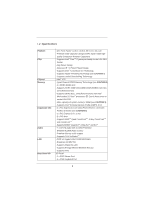
® CoreTM i7 processor family for the LGA 2011 Socket - Digi Power Design - Advanced 5 + 1 Power Phase Design - Supports Intel® Turbo Boost 2.0 Technology - Supports Hyper-Threading Technology (see CAUTION 1) - Supports Untied Overclocking Technology - Intel® X79 - Quad Channel DDR3 Memory Technology - ASRock X79 Extreme3 | User Manual - Page 7
, support RAID (RAID 0, RAID 1, RAID 5, RAID 10 and Intel Rapid Storage3.0), NCQ, AHCI and Hot Plug functions - 3 x SATA3 6.0Gb/s connectors - 1 x IR header - 1 x CIR header - 1 x COM port header - 1 x HDMI_SPDIF header - 1 x Power LED header - CPU/Chassis/Power/SB FAN connector - 24 pin ATX power - ASRock X79 Extreme3 | User Manual - Page 8
, VCCSA, DRAM, VTT, CPU PLL, PCH1.1V, PCH1.5V Voltage Multi-adjustment Support CD - Drivers, Utilities, AntiVirus Software (Trial Version), CyberLink MediaEspresso 6.5 Trial, ASRock Software Suite (ASRock MAGIX Multimedia Suite - OEM) Unique Feature - ASRock Extreme Tuning Utility (AXTU) (see - ASRock X79 Extreme3 | User Manual - Page 9
for system usage under Windows® 7 / VistaTM / XP. For Windows® OS with 64-bit CPU, there is no such limitation. You can use ASRock XFast RAM to utilize the memory that Windows® cannot use. 4. Currently Intel® Socket 2011 Sandy Bridge-E Processor doesn't support PCIE 3.0, but this motherboard is - ASRock X79 Extreme3 | User Manual - Page 10
drive must use FAT32/16/12 file system. 8. If you desire a faster, less restricted way of charging your Apple devices, such as iPhone/iPad/iPod Touch, ASRock has prepared a wonderful solution for you - ASRock APP Charger. Simply install the APP Charger driver, it makes your iPhone charge much quickly - ASRock X79 Extreme3 | User Manual - Page 11
motherboard functions properly and unplug the power cord, then plug it back again. To improve heat dissipation, remember to spray thermal grease between the CPU and the heatsink when you install the PC system. 18. Intel Rapid Storage Technology enterprise 3.0 and ASRock XFast RAM are not supported - ASRock X79 Extreme3 | User Manual - Page 12
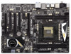
1.3 Motherboard Layout 1 ATX 12V Power Connector (ATX12V1) 21 Clear CMOS Jumper (CLRCMOS1) 2 2 x 240-pin DDR3 DIMM Slots 22 Chassis Fan Connector (CHA_FAN3) (DDR3_A1, DDR3_B1, Black) 23 Chassis Fan Connector (CHA_FAN1) 3 2011-Pin CPU Socket 24 USB 2.0 Header (USB_10_11, Black) 4 CPU Fan - ASRock X79 Extreme3 | User Manual - Page 13
(USB01) * 4 LAN RJ-45 Port 5 Side Speaker (Gray) 6 Rear Speaker (Black) 7 Central / Bass (Orange) 8 Line In (Light Blue) ** 9 Front Speaker (Lime) 10 11 12 13 *** 14 15 16 17 Microphone (Pink) USB 2.0 Ports (USB45) USB 3.0 Ports (USB3_0_1) USB 2.0 Ports (USB23) eSATA3 Connector Optical SPDIF Out - ASRock X79 Extreme3 | User Manual - Page 14
to the front panel audio header. After restarting your computer, you will find "Mixer" tool on your system. Please select "Mixer ToolBox" , click "Enable playback multi-streaming", and click "ok". Choose "2CH " to use front panel audio. *** eSATA3 connector supports SATA Gen3 in cable 1M. 14 - ASRock X79 Extreme3 | User Manual - Page 15
that comes with the component. 5. When placing screws into the screw holes to secure the mother- board to the chassis, please do not over-tighten the screws! Doing so may damage the motherboard. Before you install or remove any component, ensure that the power is switched off or the power cord is - ASRock X79 Extreme3 | User Manual - Page 16
2.3 CPU Installation For the installation of Intel 2011-Pin CPU, please follow the steps below. 2011-Pin Socket Overview Before you insert the 2011-Pin CPU into the socket, please check if the CPU surface is unclean or if there are any bent pins in the socket. Do not force to insert the CPU into the - ASRock X79 Extreme3 | User Manual - Page 17
Verify that the CPU is within the socket and properly mated to the orient keys. Step 3. Close the socket: Step 3-1. Flip the load plate onto the IHS, then the cover will automatically come off by itself. The cover must be placed if returning the motherboard for after service. Step 3-2. Press down - ASRock X79 Extreme3 | User Manual - Page 18
Heatsink This motherboard is equipped with 2011-Pin socket that supports Intel 2011-Pin CPU. Please adopt the type of heatsink and cooling fan compliant with Intel 2011Pin CPU to dissipate heat. Before you installed the heatsink, you need to spray thermal interface material between the CPU and the - ASRock X79 Extreme3 | User Manual - Page 19
a DDR or DDR2 memory module into a DDR3 slot; otherwise, this motherboard and DIMM may be damaged. Installing a DIMM Please make sure to disconnect power supply before adding or removing DIMMs or the system components. Step 1. Unlock the DIMM slot by pressing the retaining clips outward. Step - ASRock X79 Extreme3 | User Manual - Page 20
. 5. Currently Intel® Socket 2011 Sandy Bridge-E Processor doesn't support PCIE 3.0, but this motherboard is already PCIE 3.0 hardware ready. It depends on Intel's CPU to enable PCIE 3.0. Please check Intel's website for information on future CPU updates and releases. Installing an expansion card - ASRock X79 Extreme3 | User Manual - Page 21
, 3-Way SLITM and Quad SLITM Operation Guide This motherboard supports NVIDIA® SLITM, 3-Way SLITM and Quad SLITM (Scalable Link Interface) technology that allows you to install up to three identical PCI Express x16 graphics cards. Currently, NVIDIA® SLITM technology supports Windows® XP / XP 64-bit - ASRock X79 Extreme3 | User Manual - Page 22
Step3. Align and insert the ASRock SLI_Bridge_2S Card to the goldfingers on each graphics card. Make sure the ASRock SLI_Bridge_2S Card is firmly in place. ASRock SLI_Bridge_2S Card Step4. Connect a VGA cable or a DVI cable to the monitor connector or the DVI connector of the graphics card that is - ASRock X79 Extreme3 | User Manual - Page 23
Three SLITM-Ready Graphics Cards Step 1. Install the identical 3-Way SLITM-ready graphics cards . Step3. Align and insert ASRock 3-Way SLI-2S1S Bridge Card to the goldfingers on each graphics card. Make sure ASRock 3-Way SLI-2S1S Bridge Card is firmly in place. ASRock 3-Way SLI-2S1S Bridge Card - ASRock X79 Extreme3 | User Manual - Page 24
2.7.2 Driver Installation and Setup Install the graphics card drivers to your system. After that, you can enable the MultiGraphics Processing Unit (GPU) feature in the NVIDIA® nView system tray utility. Please follow the below procedures to enable the multi-GPU feature. For Windows® XP / XP 64-bit - ASRock X79 Extreme3 | User Manual - Page 25
. In Set PhysX GPU acceleration item, please select Enabled. In Select an SLI configuration item, please select Enable SLI. And click Apply. F. Reboot your system. G. You can freely enjoy the benefit of SLITM or Quad SLITM feature. 25 - ASRock X79 Extreme3 | User Manual - Page 26
for PhysX item, please select Enabled. In Select an SLI configuration item, please select Enable 3-way SLI. And click Apply. C. Reboot your system. D. You can freely enjoy the benefit of 3-Way SLITM feature. * SLITM appearing here is a registered trademark of NVIDIA® Technologies Inc., and is used - ASRock X79 Extreme3 | User Manual - Page 27
feature is supported with Windows® XP with Service Pack 2 / VistaTM / 7 OS. 3-way CrossFireXTM and Quad CrossFireXTM feature are supported with Windows® VistaTM / 7 OS only. Please check AMD website for ATITM CrossFireXTM driver updates. 1. If a customer incorrectly configures their system they will - ASRock X79 Extreme3 | User Manual - Page 28
Step 2. Connect two Radeon graphics cards by installing CrossFire Bridge on CrossFire Bridge Interconnects on the top of Radeon graphics cards. (CrossFire Bridge is provided with the graphics card you purchase, not bundled with this motherboard. Please refer to your graphics card vendor for details - ASRock X79 Extreme3 | User Manual - Page 29
Three CrossFireXTM-Ready Graphics Cards Step 1. Install the identical 3-Way CrossFireXTM-ready graphics cards CrossFireTM Bridge is provided with the graphics card you purchase, not bundled with this motherboard. Please refer to your graphics card vendor for details.) CrossFireTM Bridge Step 5. - ASRock X79 Extreme3 | User Manual - Page 30
check AMD website for ATITM driver updates. Step 3. Step 4. Step 5. Install the required drivers to your system. For Windows® XP OS: A. AMD recommends Windows® XP Service Pack 2 or higher to be installed (If you have Windows® XP Service Pack 2 or higher installed in your system, there is no need - ASRock X79 Extreme3 | User Manual - Page 31
, please check AMD website for updates and details. 2.9 Surround Display Feature This motherboard supports Surround Display upgrade. With the external add-on PCI Express VGA cards, you can easily enjoy the benefits of Surround Display feature. For detailed instructions, please refer to the document - ASRock X79 Extreme3 | User Manual - Page 32
. Step3. GND IRTX IRRX ATX+5VSB Install Multi-Angle CIR Receiver to the support Hot-Plug function. Please install it before you boot the system. * ASRock Smart Remote is only supported by some of ASRock motherboards. Please refer to ASRock website for the motherboard support list: http://www.asrock - ASRock X79 Extreme3 | User Manual - Page 33
2.11 ASRock XFast Charger Operation Guide ASRock XFast Charger is the best and capable of Charging the BC 1.1 standard smart devices. Please refer to below instruction for proper operation. This motherboard provides two USB ports for ASRock XFast Charger: 1. USB 2.0 port (USB0) on the I/O panel see - ASRock X79 Extreme3 | User Manual - Page 34
need to clear the CMOS when you just finish updating the BIOS, you must boot up the system first, and then shut it down before you do the clear-CMOS action. Please be noted that the password, date, time, user default profile, 1394 GUID and MAC address will be cleared only if the - ASRock X79 Extreme3 | User Manual - Page 35
caps over the headers and connectors will cause permanent damage of the motherboard! SATA2_3 SATA2_1 SATA2_2 SATA2_0 Serial ATA2 Connectors (SATA2_0_1: see p. : see p.12, No. 11) (SATA3_0_1: see p.12, No. 15) These three Serial ATA3 (SATA3) connectors support SATA data cables for internal storage - ASRock X79 Extreme3 | User Manual - Page 36
Jack Sensing, but the panel wire on the chassis must support HDA to function correctly. Please follow the instruction in our manual and chassis manual to install your system. 2. If you use AC'97 audio panel, please install it to the front panel audio header as below: A. Connect Mic_IN (MIC) to - ASRock X79 Extreme3 | User Manual - Page 37
the cables. PWRBTN (Power Switch): Connect to the power switch on the chassis front panel. You may configure the way to turn off your system using the power switch. RESET (Reset Switch): Connect to the reset switch on the chassis front panel. Press the reset switch to restart the computer - ASRock X79 Extreme3 | User Manual - Page 38
4-Pin CPU fan (Quiet Fan) support, the 3-Pin CPU fan still can work successfully even without the fan speed control function. If you plan to connect the 3-Pin CPU fan to the CPU fan connector on this motherboard, please connect it to Pin 1-3. Pin 1-3 Connected 3-Pin Fan Installation (3-pin - ASRock X79 Extreme3 | User Manual - Page 39
supply along with Pin 1 and Pin 13. 20-Pin ATX Power Supply Installation 1 13 ATX 12V Power Connector (8-pin ATX12V1) (see p.12 No. 1) 5 1 8 4 Please connect an ATX 12V power supply to this connector. Though this motherboard provides 8-pin ATX 12V power connector, it can still work if you - ASRock X79 Extreme3 | User Manual - Page 40
header, providing SPDIF audio output to HDMI VGA card, allows the system to connect HDMI Digital TV/ projector/LCD devices. Please connect the HDMI_SPDIF connector of HDMI VGA card to this header. 2.14 Smart Switches The motherboard has a smart switch: Clear CMOS switch. Clear CMOS Switch (CLRCBTN - ASRock X79 Extreme3 | User Manual - Page 41
adopts Intel® X79 chipset that supports Serial ATA (SATA) / Serial ATA2 (SATA2) hard disks and RAID (RAID 0, RAID 1, RAID 5, RAID 10 and Intel Rapid Storage3.0) functions. You may install SATA / SATA2 hard disks on this motherboard for internal storage devices. This section will guide you to install - ASRock X79 Extreme3 | User Manual - Page 42
insert and remove the SATA / SATA2 HDDs while the system is still power-on and in working condition. 2.18 Hot Plug and Hot Swap Functions for SATA3 HDDs This motherboard supports Hot Plug and Hot Swap functions for SATA3 in RAID / AHCI mode. Intel® X79 and ASMedia ASM1061 chipsets provide hardware - ASRock X79 Extreme3 | User Manual - Page 43
SATA / SATA2 / SATA3 driver is installed into system properly. The latest SATA / SATA2 / SATA3 driver is available on our support website: www.asrock.com 4. Make sure to use the SATA power cable & data cable, which are from our motherboard package. 5. Please follow below instructions step by step to - ASRock X79 Extreme3 | User Manual - Page 44
supply 1x4-pin cable. Step 2 Connect SATA data cable to the motherboard's SATA2 / SATA3 connector. SATA power cable 1x4-pin power connector of attention, before you process the Hot Unplug: Please do follow below instruction sequence to process the Hot Unplug, improper procedure will cause the SATA - ASRock X79 Extreme3 | User Manual - Page 45
optical drive to boot your system, and follow the instruction to install OS on your system. When you see "Where do you want to install Windows?" page, please insert our Support CD to your system, and click the "Load Driver" button to load Intel® RAID drivers. Intel® RAID drivers are located in the - ASRock X79 Extreme3 | User Manual - Page 46
path: .. \ RAID Installation Guide and the document in the support CD, "Guide to Intel Rapid Storage", which is located in the folder at the following path: .. \ Intel Rapid Storage Information If you want to make the USB flash driver disk, please copy above Intel® RAID drivers from our Support CD to - ASRock X79 Extreme3 | User Manual - Page 47
Operation Mode" to [IDE]. (For SATA3_A0 port.) STEP 2: Install Windows® 7 / 7 64-bit / VistaTM / VistaTM 64-bit OS on your system. 2.23 Untied Overclocking Technology This motherboard supports Untied Overclocking Technology, which means during overclocking, FSB enjoys better margin due to fixed PCI - ASRock X79 Extreme3 | User Manual - Page 48
to configure your system. The UEFI chip on the motherboard stores the UEFI SETUP system chassis. You may also restart by turning the system off and then back on. Because the UEFI software is constantly being updated up the system time/date information OC Tweaker To set up overclocking features - ASRock X79 Extreme3 | User Manual - Page 49
the Exit Screen or exit the current screen 3.2 Main Screen When you enter the UEFI SETUP UTILITY, the Main screen will appear and display the system overview. System Browser System Browser can let you easily check your current - ASRock X79 Extreme3 | User Manual - Page 50
[Disabled]. If you install Windows® VistaTM / 7 and want to enable this function, please set this item to [Enabled]. This item will be hidden if the current CPU does not support Intel SpeedStep technology. Please note that enabling this function may reduce CPU voltage and lead to system stability or - ASRock X79 Extreme3 | User Manual - Page 51
Manual]. The default value is [Auto]. Core Current Limit Use this item to add voltage when CPU is in Turbo mode. Additional Turbo Voltage Use this item to add voltage when CPU Auto]. DRAM Frequency If [Auto] is selected, the motherboard will detect the memory module(s) inserted and assign the - ASRock X79 Extreme3 | User Manual - Page 52
setting. The default is [Auto]. DRAM tRTP Use this item to change Read to Precharge (tRTP) Auto/Manual setting. The default is [Auto]. DRAM tFAW Use this item to change Four Activate Window (tFAW) Auto/Manual setting. The default is [Auto]. DRAM tCWL Use this item to change CAS# Write Latency (tCWL - ASRock X79 Extreme3 | User Manual - Page 53
ODT NOM (CH D) setting. The default is [Auto]. Voltage Control CPU Core Voltage Use this to select CPU Core Voltage. The default value is [Auto]. CPU Load-Line Calibration CPU Load-Line Calibration helps prevent CPU voltage droop when the system is under heavy load. VCCSA Voltage Use this to select - ASRock X79 Extreme3 | User Manual - Page 54
you may set the configurations for the following items: CPU Configuration, North Bridge Configuration, South Bridge Confi flash utility embedded in Flash ROM. This convenient UEFI update tool allows you to update system UEFI without entering operating systems first like MS-DOS or Windows®. Just save the - ASRock X79 Extreme3 | User Manual - Page 55
3.4.1 CPU Configuration CPU Ratio Setting Use this item to change the ratio value of this motherboard. Intel Hyper Threading Technology To enable this feature, a computer system with an Intel processor that supports Hyper-Threading technology and an operating system that includes optimization for - ASRock X79 Extreme3 | User Manual - Page 56
[Disabled]. If you install Windows® VistaTM / 7 and want to enable this function, please set this item to [Enabled]. This item will be hidden if the current CPU does not support Intel SpeedStep technology. Please note that enabling this function may reduce CPU voltage and lead to system stability or - ASRock X79 Extreme3 | User Manual - Page 57
select PCIE 4 Link Speed. The default value is [GEN2]. PCIE 4 Link Width This allows you to select PCIE 4 Link Width. The default value is [x8]. Intel(R) VT for Directed I/O Configuration Intel(R) VT-d Use this item to enable/disable Intel(R) Virtualization Technology for Directed I/O. 57 - ASRock X79 Extreme3 | User Manual - Page 58
power resumes and the system starts to boot up when the power recovers. Deep Sx Mobile platforms support Deep S4/S5 in DC only and desktop platforms support Deep S4/S5 in this option to [Enabled] if you plan to use this motherboard to submit Windows® VistaTM certification. Good Night LED Use this item - ASRock X79 Extreme3 | User Manual - Page 59
The default value is [AHCI Mode]. AHCI (Advanced Host Controller Interface) supports NCQ and other new features that will improve SATA disk performance but IDE figuration options: [Disabled] and [Enabled]. We recommend to use Intel® X79 SATA ports (SATA3_0, SATA3_1 and SATA2_0 to SATA2_3) for your - ASRock X79 Extreme3 | User Manual - Page 60
3.4.5 Super IO Configuration Serial Port Use this item to enable or disable the onboard serial port. Serial Port Address Use this item to set the address for the onboard serial port. Configuration options: [3F8h / IRQ4] and [3E8h / IRQ4]. Infrared Port Use this item to enable or disable the onboard - ASRock X79 Extreme3 | User Manual - Page 61
disable the Suspend-toRAM feature. Select [Auto] will enable this feature if the OS supports it. Check Ready Bit Use this item to enable or disable the feature Check this item to enable or disable PS/2 keyboard to turn on the system from the power-soft-off mode. PCI Devices Power On Use this item to - ASRock X79 Extreme3 | User Manual - Page 62
use of USB 2.0 controller. USB 3.0 Controller Use this item to enable or disable the use of USB 3.0 controller. Legacy USB Support Use this option to select legacy support for USB devices. There are four configuration options: [Enabled], [Auto], [Disabled] and [UEFI Setup Only]. The default value is - ASRock X79 Extreme3 | User Manual - Page 63
3.4.8 ME Subsystem Intel ME Subsystem Configuration ME Version 63 - ASRock X79 Extreme3 | User Manual - Page 64
system, including the parameters of the CPU temperature, motherboard temperature, CPU fan speed, chassis fan speed, and the critical voltage. CPU Fan 1 & 2 Setting This allows you to set CPU This allows you to set the target temperature to activate ASRock X-FAN. The default value is [50oC/122oF]. - ASRock X79 Extreme3 | User Manual - Page 65
option to adjust AddOn ROM Display. If you enable the option "Full Screen Logo" but you want to see the AddOn ROM information when the system boots, please select [Enabled]. Configuration options: [Enabled] and [Disabled]. The default value is [Enabled]. Boot From Onboard LAN Use this item to enable - ASRock X79 Extreme3 | User Manual - Page 66
3.7 Security Screen In this section, you may set or change the supervisor/user password for the system. For the user password, you may also clear it. 66 - ASRock X79 Extreme3 | User Manual - Page 67
3.8 Exit Screen Save Changes and Exit When you select this option, the following message "Save configuration changes and exit setup?" will pop-out. Select [Yes] to save the changes and exit the UEFI SETUP UTILITY. Discard Changes and Exit When you select this option, the following message "Discard - ASRock X79 Extreme3 | User Manual - Page 68
the menu. 4.2.2 Drivers Menu The Drivers Menu shows the available device's drivers if the system detects installed devices. Please install the necessary drivers to activate the devices. 4.2.3 Utilities Menu The Utilities Menu shows the application softwares that the motherboard supports. Click on - ASRock X79 Extreme3 | User Manual - Page 69
OS on a HDD Larger Than 2TB in AHCI Mode This motherboard adopts UEFI BIOS that allows Windows® OS to be installed on a large size HDD (>2TB). Please follow the procedures below to install the operating system. 1. Please make sure to use Windows® VistaTM 64-bit (with SP1 or above) or Windows - ASRock X79 Extreme3 | User Manual - Page 70
OR copy the file from ASRock motherboard support CD. (please copy the files under following directory: 32 bit: ..\i386\Win7_Vista_Intel_v3.0.0.1112 64-bit: ..\AMD64\Win7-64_Vista64_Intel_v3.0.0.1112 3. Create RAID array for you system. Please refer to "Intel RAID Installation Guide" file for details - ASRock X79 Extreme3 | User Manual - Page 71
Installation Guide to install OS. If you install Windows® 7 64-bit / VistaTM 64-bit on a large hard disk (ex. Disk volume > 2TB), it may take more time to boot into Windows® or install driver/utilities. If you encounter this problem, you will need to follow the instructions below to fix this problem - ASRock X79 Extreme3 | User Manual - Page 72
B. Disable "Volume Shadow Copy" service. a. Type "computer management" in the Start Menu, then press "Enter". b. Go to "Services and Applications>Services"; Then double click "Volume Shadow Copy". 72 - ASRock X79 Extreme3 | User Manual - Page 73
"OK". C. Reboot your system. D. After reboot, please start to install motherboard drivers and utilities. Windows® 7 64-bit: A. Please request the hotfix KB2505454 through this link: http://support.microsoft.com/kb/2505454/ B. After installing Windows® 7 64-bit, install the hotfix kb2505454. (This
-
 1
1 -
 2
2 -
 3
3 -
 4
4 -
 5
5 -
 6
6 -
 7
7 -
8
-
9
-
10
-
11
-
12
-
13
-
14
-
15
-
16
-
17
-
18
-
19
-
20
-
21
-
22
-
23
-
24
-
25
-
26
-
27
-
28
-
29
-
30
-
31
-
32
-
33
-
34
-
35
-
36
-
37
-
38
-
39
-
40
-
41
-
42
-
43
-
44
-
45
-
46
-
47
-
48
-
49
-
50
-
51
-
52
-
53
-
54
-
55
-
56
-
57
-
58
-
59
-
60
-
61
-
62
-
63
-
64
-
65
-
66
-
67
-
68
-
69
-
70
-
71
-
72
-
73
 |
 |
1
X79 Extreme3
User Manual
Version 1.0
Published October 2011
Copyright©2011 ASRock INC. All rights reserved.