ASRock X79 Extreme4 User Manual
ASRock X79 Extreme4 Manual
 |
View all ASRock X79 Extreme4 manuals
Add to My Manuals
Save this manual to your list of manuals |
ASRock X79 Extreme4 manual content summary:
- ASRock X79 Extreme4 | User Manual - Page 1
X79 Extreme4 User Manual Version 1.0 Published September 2011 Copyright©2011 ASRock INC. All rights reserved. 1 - ASRock X79 Extreme4 | User Manual - Page 2
commitment by ASRock. ASRock assumes no responsibility for any errors or omissions that may appear in this manual. With respect to the contents of this manual, ASRock does not , USA ONLY The Lithium battery adopted on this motherboard contains Perchlorate, a toxic substance controlled in Perchlorate - ASRock X79 Extreme4 | User Manual - Page 3
and CPU fan 18 2.5 Installation of Memory Modules (DIMM 19 2.6 Expansion Slots (PCI and PCI Express Slots 20 2.7 SLITM, 3-Way SLITM and Quad SLITM Operation Guide ... 21 2.8 CrossFireXTM, 3-Way CrossFireXTM and Quad CrossFireXTM Operation Guide 27 2.9 Surround Display Features 31 2.10 ASRock - ASRock X79 Extreme4 | User Manual - Page 4
Health Event Monitoring Screen 70 3.6 Boot Screen 71 3.7 Security Screen 72 3.8 Exit Screen 73 4 Software Support 74 4.1 Install Operating System 74 4.2 Support CD Information 74 4.2.1 Running Support CD 74 4.2.2 Drivers Menu 74 4.2.3 Utilities Menu 74 4.2.4 Contact Information 74 4 - ASRock X79 Extreme4 | User Manual - Page 5
you are using. www.asrock.com/support/index.asp 1.1 Package Contents ASRock X79 Extreme4 Motherboard (ATX Form Factor: 12.0-in x 9.6-in, 30.5 cm x 24.4 cm) ASRock X79 Extreme4 Quick Installation Guide ASRock X79 Extreme4 Support CD 4 x Serial ATA (SATA) Data Cables (Optional) 1 x I/O Panel Shield - ASRock X79 Extreme4 | User Manual - Page 6
slots - Supports DDR3 2400+(OC)/1600/1333/1066/800 non-ECC, un-buffered memory - Supports DDR3 ECC, un-buffered memory with Intel® Workstation 1S Xeon® processors E5 2xxx & 4xxx series in socket LGA 2011 - Max. capacity of system memory: 32GB (see CAUTION 3) - Supports Intel® Extreme Memory Profile - ASRock X79 Extreme4 | User Manual - Page 7
Ports - 1 x RJ-45 LAN Port with LED (ACT/LINK LED and SPEED LED) - 1 x IEEE 1394 Port - 1 x Clear CMOS Switch with LED - HD Audio Jack: Side Speaker/Rear Speaker/Central/Bass/ Line in/Front Speaker/Microphone (see CAUTION 5) - 2 x SATA3 6.0 Gb/s connectors by Intel® X79, support RAID (RAID 0, RAID - ASRock X79 Extreme4 | User Manual - Page 8
2.3.1 Support - CPU, VCCSA, DRAM, VTT, CPU PLL, PCH1.1V, PCH1.5V Voltage Multi-adjustment Support CD - Drivers, Utilities, AntiVirus Software (Trial Version), CyberLink MediaEspresso 6.5 Trial, ASRock Software Suite (ASRock MAGIX Multimedia Suite - OEM) Unique Feature - ASRock Extreme Tuning - ASRock X79 Extreme4 | User Manual - Page 9
/ XP. For Windows® OS with 64-bit CPU, there is no such limitation. You can use ASRock XFast RAM to utilize the memory that Windows® cannot use. 4. Currently Intel® Socket 2011 Sandy Bridge-E Processor doesn't support PCIE 3.0, but this motherboard is already PCIE 3.0 hardware ready. It depends on - ASRock X79 Extreme4 | User Manual - Page 10
smart devices. Please refer to page 33 for details. 13. ASRock XFast RAM is a new function that is included into ASRock Extreme Tuning Utility (AXTU). It fully utilizes the memory space that cannot be used under Windows® OS 32-bit CPU. ASRock XFast RAM shortens the loading time of previously visited - ASRock X79 Extreme4 | User Manual - Page 11
during the BIOS update process, ASRock Crashless BIOS will automatically finish the BIOS update procedure after regaining power. Please note that BIOS files need to be placed in the root directory of your USB disk. Only USB2.0 ports support this feature. 16. Although this motherboard offers stepless - ASRock X79 Extreme4 | User Manual - Page 12
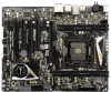
PCIE1 42 PCIE2 CHA_FAN2 11 SATA3 6Gb/s 12 13 SATA2_2_3 XFast LAN SB_FAN1 14 41 PCI1 SATA2_0_1 Intel 15 40 PCIE3 X79 SATA3_0_1 Super 16 I/O X79 Extreme4 CMOS 39 PCI2 Battery 64Mb BIOS 17 SATA3_A0_A1 2 oz Copper PCB XFast USB 18 38 37 PCIE4 AUDIO CODEC PCI Express - ASRock X79 Extreme4 | User Manual - Page 13
ACT/LINK SPEED LED LED Off No Link Off 10Mbps connection Blinking Data Activity Orange 100Mbps connection On Link Green 1Gbps connection LAN Port ** If you use 2-channel speaker, please connect the speaker's plug into "Front Speaker Jack". See the table below for connection details - ASRock X79 Extreme4 | User Manual - Page 14
To enable Multi-Streaming function, you need to connect a front panel audio cable to the front panel audio header. After restarting your computer, you will find "Mixer" tool , or select "Realtek HDA Audio 2nd output" to use front panel audio. *** eSATA3 connector supports SATA Gen3 in cable 1M. 14 - ASRock X79 Extreme4 | User Manual - Page 15
Precautions Take note of the following precautions before you install motherboard components or change any motherboard settings. 1. Unplug the power cord from the wall socket before touching any components. 2. To avoid damaging the motherboard's components due to static electricity, NEVER place your - ASRock X79 Extreme4 | User Manual - Page 16
installation of Intel 2011-Pin CPU, please follow the steps below. 2011-Pin Socket Overview Before you insert the 2011-Pin CPU into the socket, please check if the CPU surface is unclean or if there are any bent pins in the socket. Do not force to insert the CPU into the socket if above situation - ASRock X79 Extreme4 | User Manual - Page 17
Verify that the CPU is within the socket and properly mated to the orient keys. Step 3. Close the socket: Step 3-1. Flip the load plate onto the IHS, then the cover will automatically come off by itself. The cover must be placed if returning the motherboard for after service. Step 3-2. Press down - ASRock X79 Extreme4 | User Manual - Page 18
Heatsink This motherboard is equipped with 2011-Pin socket that supports Intel 2011-Pin CPU. Please adopt the type of heatsink and cooling fan compliant with Intel 2011Pin CPU to dissipate heat. Before you installed the heatsink, you need to spray thermal interface material between the CPU and the - ASRock X79 Extreme4 | User Manual - Page 19
2.5 Installation of Memory Modules (DIMM) This motherboard provides four 240-pin DDR3 (Double Data Rate 3) DIMM slots, and supports Quad Channel Memory Technology. For quad channel configuration, you always need to install identical (the same brand, speed, size and chip-type) DDR3 DIMM in the slots: - ASRock X79 Extreme4 | User Manual - Page 20
width cards, such as Gigabit LAN card, SATA2 card, etc. Intel® Socket 2011 Sandy Bridge-E Processor doesn't support PCIE 3.0, but this motherboard is already PCIE 3.0 hardware ready. It depends on Intel's CPU to enable PCIE 3.0. Please check Intel's website for information on future CPU updates - ASRock X79 Extreme4 | User Manual - Page 21
, 3-Way SLITM and Quad SLITM Operation Guide This motherboard supports NVIDIA® SLITM, 3-Way SLITM and Quad SLITM (Scalable Link Interface) technology that allows you to install up to three identical PCI Express x16 graphics cards. Currently, NVIDIA® SLITM technology supports Windows® XP / XP 64-bit - ASRock X79 Extreme4 | User Manual - Page 22
Step3. Align and insert the ASRock SLI_Bridge_2S Card to the goldfingers on each graphics card. Make sure the ASRock SLI_Bridge_2S Card is firmly in place. ASRock SLI_Bridge_2S Card Step4. Connect a VGA cable or a DVI cable to the monitor connector or the DVI connector of the graphics card that is - ASRock X79 Extreme4 | User Manual - Page 23
3-Way SLI-2S1S Bridge Card to the goldfingers on each graphics card. Make sure ASRock 3-Way SLI-2S1S Bridge Card is firmly in place. ASRock 3-Way SLI-2S1S Bridge Card Step4. Connect a VGA cable or a DVI cable to the monitor connector or the DVI connector of the graphics card that is inserted to - ASRock X79 Extreme4 | User Manual - Page 24
Installation and Setup Install the graphics card drivers to your system. After that, you can enable the MultiGraphics Processing Unit (GPU) feature in the NVIDIA® nView system tray utility. Please follow the below - ASRock X79 Extreme4 | User Manual - Page 25
For Windows® VistaTM / VistaTM 64-bit / 7 / 7 64-bit OS: (For SLITM and Quad SLITM mode) A. Click the Start icon on your Windows taskbar. B. From the pop-up menu, select All Programs, and then click NVIDIA Corporation. C. Select NVIDIA Control Panel tab. D. Select Control Panel tab. E. From the pop- - ASRock X79 Extreme4 | User Manual - Page 26
For Windows® VistaTM / VistaTM 64-bit / 7 / 7 64-bit OS: (For 3-Way SLITM mode) A. Follow steps A to D on page 25. B. From the pop-up menu, select Set SLI and PhysX configuration. In Select a hardware acceleration setting for PhysX item, please select Enabled. In Select an SLI configuration item, - ASRock X79 Extreme4 | User Manual - Page 27
Guide This motherboard supports supported with Windows® XP with Service Pack 2 / VistaTM / 7 OS. 3-way CrossFireXTM and Quad CrossFireXTM feature are supported with Windows® VistaTM / 7 OS only. Please check AMD website for ATITM CrossFireXTM driver updates manuals for detailed installation guide. - ASRock X79 Extreme4 | User Manual - Page 28
. (CrossFire Bridge is provided with the graphics card you purchase, not bundled with this motherboard. Please refer to your graphics card vendor for details.) CrossFire Bridge or Step 3. Connect the DVI monitor cable to the DVI connector on the Radeon graphics card on PCIE1 slot. (You may use - ASRock X79 Extreme4 | User Manual - Page 29
. (CrossFireTM Bridge is provided with the graphics card you purchase, not bundled with this motherboard. Please refer to your graphics card vendor for details.) CrossFireTM Bridge Step 5. Connect the DVI monitor cable to the DVI connector on the Radeon graphics card on PCIE1 slot. (You may use - ASRock X79 Extreme4 | User Manual - Page 30
utility to uninstall any previously installed Catalyst drivers prior to installation. Please check AMD website for ATITM driver updates. Step 3. Step 4. Step 5. Install the required drivers to your system. For Windows® XP OS: A. AMD recommends Windows® XP Service Pack 2 or higher to be installed - ASRock X79 Extreme4 | User Manual - Page 31
, please check AMD website for updates and details. 2.9 Surround Display Feature This motherboard supports Surround Display upgrade. With the external add-on PCI Express VGA cards, you can easily enjoy the benefits of Surround Display feature. For detailed instructions, please refer to the document - ASRock X79 Extreme4 | User Manual - Page 32
is compatible with most of the chassis on the market. 3. The Multi-Angle CIR Receiver does not support Hot-Plug function. Please install it before you boot the system. * ASRock Smart Remote is only supported by some of ASRock motherboards. Please refer to ASRock website for the motherboard support - ASRock X79 Extreme4 | User Manual - Page 33
to Apple devices, it is also capable of Charging the BC 1.1 standard smart devices. Please refer to below instruction for proper operation. This motherboard provides two USB ports for ASRock XFast Charger: 1. USB 2.0 port (USB0) on the I/O panel see p.13 No. 14 2. USB 2.0 port (USB6) header see p.12 - ASRock X79 Extreme4 | User Manual - Page 34
to clear the CMOS when you just finish updating the BIOS, you must boot up the system first, and then shut it down before you do the clear-CMOS action. Please be noted that the password, date, time, user default profile, 1394 GUID and MAC address will be cleared only if the - ASRock X79 Extreme4 | User Manual - Page 35
Either end of the SATA data cable can be connected to the SATA / SATA2 / SATA3 hard disk or the SATA2 / SATA3 connector on this motherboard. Besides six default USB 2.0 ports on the I/O panel, there are three USB 2.0 headers on this motherboard. Each USB 2.0 header can support two USB 2.0 ports. 35 - ASRock X79 Extreme4 | User Manual - Page 36
motherboard. This USB 3.0 header can support cable that allows convenient connection and control of audio devices. 1. High Definition Audio supports Jack Sensing, but the panel wire on the chassis must support HDA to function correctly. Please follow the instruction in our manual and chassis manual - ASRock X79 Extreme4 | User Manual - Page 37
and system status indicator on the chassis to this header according to the pin assignments below. Note the positive and negative pins before connecting the cables. PWRBTN (Power Switch): Connect to the power switch on the chassis front panel. You may configure the way to turn off your system using - ASRock X79 Extreme4 | User Manual - Page 38
/S4 state or S5 state (power off). Please connect the fan cables to the fan connectors and match the black wire to the ground pin. CHA_FAN1, CHA_FAN2 and CHA_FAN3 support Fan Control. SB_FAN1 Supports Quiet Fan. Please connect the CPU fan cable to the connector and match the black wire to the ground - ASRock X79 Extreme4 | User Manual - Page 39
) support, the 3-Pin CPU fan still can work successfully even without the fan speed control function. If you plan to connect the 3-Pin CPU fan to the CPU fan connector on this motherboard, please connect it to Pin 1-3. Pin 1-3 Connected 3-Pin Fan Installation (3-pin CPU_FAN2) (see p.12 No. 4) ATX - ASRock X79 Extreme4 | User Manual - Page 40
default IEEE 1394 port on the I/O panel, there is one IEEE 1394 header (FRONT_1394) on this motherboard. This IEEE 1394 header can support one IEEE 1394 port. This COM1 header supports a serial port module. HDMI_SPDIF Header (2-pin HDMI_SPDIF1) (see p.12 No. 35) HDMI_SPDIF header, providing SPDIF - ASRock X79 Extreme4 | User Manual - Page 41
2.14 Smart Switches The motherboard has three smart switches: power switch, reset switch and clear CMOS switch, allowing users to quickly turn on/off or reset the system to clear - ASRock X79 Extreme4 | User Manual - Page 42
AMI SEC error codes Microcode not found Microcode not loaded PEI Core is started Pre-memory CPU initialization is started Pre-memory CPU initialization (CPU module specific) Pre-memory CPU initialization (CPU module specific) Pre-memory CPU initialization (CPU module specific) Pre-memory North Bridge - ASRock X79 Extreme4 | User Manual - Page 43
Unspecified memory initialization error Memory not installed Invalid CPU type or Speed CPU mismatch CPU self test failed or possible CPU cache error CPU micro-code is not found or micro-code update is failed Internal CPU error reset PPI is not available Reserved for future AMI error codes S3 Resume - ASRock X79 Extreme4 | User Manual - Page 44
Services CPU DXE initialization is started CPU DXE initialization (CPU module specific) CPU DXE initialization (CPU module specific) CPU DXE initialization (CPU module specific) CPU DXE initialization (CPU DXE codes OEM DXE initialization codes Boot Device Selection (BDS) phase is started Driver - ASRock X79 Extreme4 | User Manual - Page 45
. Out of Resources No Space for Legacy Option ROM No Console Output Devices are found No Console Input Devices are found Invalid password Error loading Boot Option (LoadImage returned error) Boot Option is failed (StartImage returned error) Flash update is failed Reset protocol is not available 45 - ASRock X79 Extreme4 | User Manual - Page 46
Connect one end of the SATA data cable to the motherboard's SATA2 con- nector. STEP 4: Connect the other end of the SATA data cable to the SATA / SATA2 hard disk. 2.17 Serial ATA3 (SATA3) Hard Disks Installation This motherboard adopts Intel® X79 chipset that supports Serial ATA3 (SATA3) hard disks - ASRock X79 Extreme4 | User Manual - Page 47
Hot Swap Functions for SATA / SATA2 HDDs This motherboard supports Hot Plug and Hot Swap functions for SATA / SATA2 in RAID / AHCI mode. Intel® X79 chipset provides hardware support for Advanced Host controller Interface (AHCI), a new programming interface for SATA host controllers developed through - ASRock X79 Extreme4 | User Manual - Page 48
is installed into system properly. The latest SATA / SATA2 / SATA3 driver is available on our support website: www.asrock.com 4. Make sure to use the SATA power cable & data cable, which are from our motherboard package. 5. Please follow below instructions step by step to reduce the risk of HDD - ASRock X79 Extreme4 | User Manual - Page 49
follow below instruction sequence to process the Hot Plug, improper procedure will cause the SATA / SATA2 / SATA3 HDD damage and data loss. Step 1 Please connect SATA power cable 1x4pin end (White) to the power supply 1x4-pin cable. Step 2 Connect SATA data cable to the motherboard's SATA2 / SATA3 - ASRock X79 Extreme4 | User Manual - Page 50
you want to manage RAID functions, you are allowed to use both "RAID Installation Guide" and "Intel Rapid Storage Information" for RAID configuration. Please refer to the document in the Support CD, "Guide to SATA Hard Disks Installation and RAID Configuration", which is located in the folder at the - ASRock X79 Extreme4 | User Manual - Page 51
Functions If you want to install Windows® XP / XP 64-bit OS on your SATA / SATA2 / SATA3 HDDs without RAID functions, please follow below steps. AHCI mode is not supported under Windows® XP / XP 64-bit. Using SATA / SATA2 / SATA3 HDDs without NCQ function STEP 1: Set Up UEFI. A. Enter UEFI SETUP - ASRock X79 Extreme4 | User Manual - Page 52
motherboard supports Untied Overclocking Technology, which means during overclocking, FSB enjoys better margin due to fixed PCI / PCIE buses. Before you enable Untied Overclocking function, please enter "Overclock Mode" option of UEFI setup to set the selection from [Auto] to [Manual]. Therefore, CPU - ASRock X79 Extreme4 | User Manual - Page 53
your system. The UEFI chip on the motherboard stores the UEFI SETUP UTILITY. You may (POST) to enter the UEFI SETUP UTILITY, otherwise, POST will continue with UEFI software is constantly being updated, the following UEFI setup screens OC Tweaker To set up overclocking features Advanced To set up - ASRock X79 Extreme4 | User Manual - Page 54
3.1.2 Navigation Keys Please check the following table for the function description of each navigation key. Navigation Key(s) Function Description / Moves cursor left or right to select Screens / Moves cursor up or down to select items + / - To change option for the selected items - ASRock X79 Extreme4 | User Manual - Page 55
set this item to [Enabled]. This item will be hidden if the current CPU does not support Intel SpeedStep technology. Please note that enabling this function may reduce CPU voltage and lead to system stability or compatibility issue with some power supplies. Please set this item to [Disable] if above - ASRock X79 Extreme4 | User Manual - Page 56
Manual]. The default value is [Auto]. Core Current Limit Use this item to add voltage when CPU is in Turbo mode. Additional Turbo Voltage Use this item to add voltage when CPU Frequency If [Auto] is selected, the motherboard will detect the memory module(s) inserted and assigns appropriate frequency - ASRock X79 Extreme4 | User Manual - Page 57
setting. The default is [Auto]. DRAM tRTP Use this item to change Read to Precharge (tRTP) Auto/Manual setting. The default is [Auto]. DRAM tFAW Use this item to change Four Activate Window (tFAW) Auto/Manual setting. The default is [Auto]. DRAM tCWL Use this item to change CAS# Write Latency (tCWL - ASRock X79 Extreme4 | User Manual - Page 58
. The default value is [Auto]. Electrical Throttling Use this item to configure Electrical Throttling. The default value is [Auto]. Memory Power Savings Mode Use this item to configure Memory Power Savings Mode. The default value is [Auto]. CKE Throttling Use this item to configure CKE Throttling. The - ASRock X79 Extreme4 | User Manual - Page 59
to select DRAM Voltage. The default value is [Auto]. VTT Voltage Use this to select VTT Voltage. The default value is [Auto]. CPU PLL Voltage Use this to select CPU PLL Voltage. The default value is [Auto]. PCH 1.1V Voltage Use this to select PCH 1.1V Voltage. The default value is [Auto - ASRock X79 Extreme4 | User Manual - Page 60
, you may set the configurations for the following items: CPU Configuration, North Bridge Configuration, South Bridge Configuration, in UEFI setup. Instant Flash Instant Flash is a UEFI flash utility embedded in Flash ROM. This convenient UEFI update tool allows you to update system UEFI without entering - ASRock X79 Extreme4 | User Manual - Page 61
enhancement to the IA-32 Intel Architecture. An IA-32 processor with "No Execute (NX) Memory Protection" can prevent data pages from being used by malicious software to execute code. This option will be hidden if the current CPU does not support No-Excute Memory Protection. Hardware Prefetcher Use - ASRock X79 Extreme4 | User Manual - Page 62
set this item to [Enabled]. This item will be hidden if the current CPU does not support Intel SpeedStep technology. Please note that enabling this function may reduce CPU voltage and lead to system stability or compatibility issue with some power supplies. Please set this item to [Disable] if above - ASRock X79 Extreme4 | User Manual - Page 63
select PCIE 3 Link Speed. The default value is [GEN2]. PCIE 4 Link Speed This allows you to select PCIE 4 Link Speed. The default value is [GEN2]. Intel(R) VT for Directed I/O Configuration Intel(R) VT-d Use this item to enable/disable - ASRock X79 Extreme4 | User Manual - Page 64
when the power recovers. Deep Sx Mobile platforms support Deep S4/S5 in DC only and desktop platforms support Deep S4/S5 in AC only. Configuration options to use this motherboard to submit Windows® VistaTM certification. Good Night LED Use this item to enable or disable Power LED and Lan LED. Onboard - ASRock X79 Extreme4 | User Manual - Page 65
AHCI Mode]. AHCI (Advanced Host Controller Interface) supports NCQ and other new features that will improve SATA disk performance but IDE mode does not have guration options: [Disabled] and [Enabled]. We recommend to use Intel® X79 SATA ports (SATA3_0, SATA3_1 and SATA2_0 to SATA2_3) for your - ASRock X79 Extreme4 | User Manual - Page 66
3.4.5 Super IO Configuration Serial Port Use this item to enable or disable the onboard serial port. Serial Port Address Use this item to set the address for the onboard serial port. Configuration options: [3F8h / IRQ4] and [3E8h / IRQ4]. Infrared Port Use this item to enable or disable the onboard - ASRock X79 Extreme4 | User Manual - Page 67
RAM Use this item to select whether to auto-detect or disable the Suspend-toRAM feature. Select [Auto] will enable this feature if the OS supports it. Check Ready Bit Use this item to enable or disable the feature Check Ready Bit. PS/2 Keyboard Power On Use this item to enable - ASRock X79 Extreme4 | User Manual - Page 68
OS and UEFI setup when [Disabled] is selected. If you have USB compatibility issue, it is recommended to select [Disabled] to enter OS. [UEFI Setup Only] - USB devices are allowed to use only under UEFI setup and Windows / Linux OS. Legacy USB 3.0 Support Use this option to enable or disable legacy - ASRock X79 Extreme4 | User Manual - Page 69
3.4.8 ME Subsystem Intel ME Subsystem Configuration ME Version 69 - ASRock X79 Extreme4 | User Manual - Page 70
CPU temperature, motherboard temperature, CPU fan speed, chassis fan speed, and the critical voltage. CPU Fan 1 & 2 Setting This allows you to set the CPU SB Temperature This allows you to set the target temperature to activate ASRock X-FAN. The default value is [50oC/122oF]. Target Fan Speed This - ASRock X79 Extreme4 | User Manual - Page 71
please select [Enabled]. Configuration options: [Enabled] and [Disabled]. The default value is [Enabled]. Boot From Onboard LAN Use this item to enable or disable the Boot From Onboard LAN feature. Boot Failure Guard Enable or disable the feature of Boot Failure Guard. Boot Failure Guard Count Enable - ASRock X79 Extreme4 | User Manual - Page 72
3.7 Security Screen In this section, you may set or change the supervisor/user password for the system. For the user password, you may also clear it. 72 - ASRock X79 Extreme4 | User Manual - Page 73
3.8 Exit Screen Save Changes and Exit When you select this option, it will pop-out the following message, "Save configuration changes and exit setup?" Select [Yes] to save the changes and exit the UEFI SETUP UTILITY. Discard Changes and Exit When you select this option, it will pop-out the following - ASRock X79 Extreme4 | User Manual - Page 74
install the necessary drivers to activate the devices. 4.2.3 Utilities Menu The Utilities Menu shows the applications software that the motherboard supports. Click on a specific item then follow the installation wizard to install it. 4.2.4 Contact Information If you need to contact ASRock or want to - ASRock X79 Extreme4 | User Manual - Page 75
a HDD Larger Than 2TB in AHCI Mode This motherboard adopts UEFI BIOS that allows Windows® OS to be installed on ® 7 64-bit. 2. Press or at system POST. Set AHCI Mode in UEFI Setup Utility > Advanced > Storage Configuration > SATA Mode. 3. Choose the item "UEFI:xxx" to boot in UEFI Setup - ASRock X79 Extreme4 | User Manual - Page 76
ash disk. You can download the driver from ASRock website. (http://download.asrock. com/drivers/Intel/SATA/Floppy_Win7-64_Win7_Vista64_Vista_XP64_ XP(v10.6.0.1002)Z68.zip) and unzip the file into the USB flash disk. OR Please copy the file from ASRock motherboard support CD. (please copy the files under - ASRock X79 Extreme4 | User Manual - Page 77
Windows® Installation Guide to install OS. If you install Windows® 7 64-bit / VistaTM 64-bit in a large hard disk (ex. Disk volume > 2TB), it may take more time to boot into Windows® or install driver/ utilities. If you encounter this problem, you will need to following instructions to fix this - ASRock X79 Extreme4 | User Manual - Page 78
B. Disable "Volume Shadow Copy" service. a. Type "computer management" in the Start Menu, then press "Enter". b. Go to "Services and Applications>Services"; Then double click "Volume Shadow Copy". 78 - ASRock X79 Extreme4 | User Manual - Page 79
then Click "OK". C. Reboot your system. D. After reboot, please start to install motherboard drivers and utilities. Windows® 7 64-bit: A. Please request the hotfix KB2505454 through this link: http://support.microsoft.com/kb/2505454/ B. After installing Windows® 7 64-bit, install the hotfix kb2505454
-
 1
1 -
 2
2 -
 3
3 -
 4
4 -
 5
5 -
 6
6 -
 7
7 -
8
-
9
-
10
-
11
-
12
-
13
-
14
-
15
-
16
-
17
-
18
-
19
-
20
-
21
-
22
-
23
-
24
-
25
-
26
-
27
-
28
-
29
-
30
-
31
-
32
-
33
-
34
-
35
-
36
-
37
-
38
-
39
-
40
-
41
-
42
-
43
-
44
-
45
-
46
-
47
-
48
-
49
-
50
-
51
-
52
-
53
-
54
-
55
-
56
-
57
-
58
-
59
-
60
-
61
-
62
-
63
-
64
-
65
-
66
-
67
-
68
-
69
-
70
-
71
-
72
-
73
-
74
-
75
-
76
-
77
-
78
-
79
 |
 |

1
X79 Extreme4
User Manual
Version 1.0
Published September 2011
Copyright©2011 ASRock INC. All rights reserved.