ASRock X79 Extreme7 User Manual
ASRock X79 Extreme7 Manual
 |
View all ASRock X79 Extreme7 manuals
Add to My Manuals
Save this manual to your list of manuals |
ASRock X79 Extreme7 manual content summary:
- ASRock X79 Extreme7 | User Manual - Page 1
X79 Extreme7 User Manual Version 1.0 Published October 2011 Copyright©2011 ASRock INC. All rights reserved. 1 - ASRock X79 Extreme7 | User Manual - Page 2
purchaser for backup purpose, without written consent of ASRock Inc. Products and corporate names appearing in this manual may or may not be registered trademarks or copyrights , USA ONLY The Lithium battery adopted on this motherboard contains Perchlorate, a toxic substance controlled in Perchlorate - ASRock X79 Extreme7 | User Manual - Page 3
of Memory Modules (DIMM 19 2.6 Expansion Slots (PCI and PCI Express Slots 21 2.7 SLITM, 3-Way SLITM and Quad SLITM Operation Guide ... 23 2.8 CrossFireXTM, 3-Way CrossFireXTM and Quad CrossFireXTM Operation Guide 29 2.9 Surround Display Features 33 2.10 ASRock Smart Remote Installation Guide 34 - ASRock X79 Extreme7 | User Manual - Page 4
2.24 Teaming Function Operation Guide 56 2.25 Untied Overclocking Technology 59 3 UEFI SETUP UTILITY 60 3.1 Introduction 60 3.1.1 Screen 80 4 Software Support 81 4.1 Install Operating System 81 4.2 Support CD Information 81 4.2.1 Running Support CD 81 4.2.2 Drivers Menu 81 4.2.3 Utilities - ASRock X79 Extreme7 | User Manual - Page 5
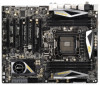
about the model you are using. www.asrock.com/support/index.asp 1.1 Package Contents ASRock X79 Extreme7 Motherboard (ATX Form Factor: 12.0-in x 9.6-in, 30.5 cm x 24.4 cm) ASRock X79 Extreme7 Quick Installation Guide ASRock X79 Extreme7 Support CD 6 x Serial ATA (SATA) Data Cables (Optional - ASRock X79 Extreme7 | User Manual - Page 6
Series Processors in Socket LGA 2011 - Digi Power Design - Advanced V12 + 2 Power Phase Design - Supports Intel® Turbo Boost 2.0 Technology - Supports Hyper-Threading Technology (see CAUTION 1) - Supports Untied Overclocking Technology - Intel® X79 - Quad Channel DDR3 Memory Technology (see CAUTION - ASRock X79 Extreme7 | User Manual - Page 7
: Side Speaker/Rear Speaker/Central/Bass/ Line in/Front Speaker/Microphone (see CAUTION 6) - 2 x SATA3 6.0 Gb/s connectors by Intel® X79, support RAID (RAID 0, RAID 1, RAID 5, RAID 10 and Intel Rapid Storage 3.0), NCQ, AHCI and "Hot Plug" functions - 2 x SATA3 6.0 Gb/s connectors by Marvell SE9182 - ASRock X79 Extreme7 | User Manual - Page 8
Support - CPU, VCCSA, DRAM, VTT, CPU PLL, PCH1.1V, PCH1.5V Voltage Multi-adjustment - Drivers, Utilities, AntiVirus Software (Trial Version), CyberLink MediaEspresso 6.5 Trial, ASRock Software Suite (ASRock MAGIX Multimedia Suite - OEM) - ASRock Extreme Tuning Utility (AXTU) (see CAUTION 7) - ASRock - ASRock X79 Extreme7 | User Manual - Page 9
is no such limitation. You can use ASRock XFast RAM to utilize the memory that Windows® cannot use. 5. Currently Intel® Socket 2011 Sandy Bridge-E Processor doesn't support PCIE 3.0, but this motherboard is already PCIE 3.0 hardware ready. It depends on Intel's CPU to enable PCIE 3.0. Please check - ASRock X79 Extreme7 | User Manual - Page 10
our website for the operation procedures of ASRock Extreme Tuning Utility (AXTU). ASRock website: http://www.asrock.com 8. ASRock Instant Flash is a BIOS ash utility embedded in Flash ROM. This convenient BIOS update tool allows you to update system BIOS without entering operating systems rst like - ASRock X79 Extreme7 | User Manual - Page 11
during the BIOS update process, ASRock Crashless BIOS will automatically nish the BIOS update procedure after regaining power. Please note that BIOS les need to be placed in the root directory of your USB disk. Only USB2.0 ports support this feature. 17. Although this motherboard offers stepless - ASRock X79 Extreme7 | User Manual - Page 12
Motherboard BIOS CMOS Battery SATA3_M4 SB_FAN1 SATA2_2_3 CHA_FAN1 LAN PHY Super I/O PCIE2 X79 Extreme7 2011-Pin CPU Socket 32 Clear CMOS Jumper (CLRCMOS1) 6 ATX 12V Power Connector (ATX12V1) 33 SPI Flash Memory 46 PCI Slot (PCI1, Black) 24 Intel X79 Chipset 47 PCI Express 3.0 x16 Slot ( - ASRock X79 Extreme7 | User Manual - Page 13
1.4 I/O Panel 1 2 3 45 6 9 7 10 8 11 19 18 17 16 1 2 * 3 4 * 5 6 7 8 9 ** 10 PS/2 Mouse Port (Green) Coaxial SPDIF Out Port LAN RJ-45 Port USB 2.0 Ports (USB45) LAN RJ-45 Port Side Speaker (Gray) Rear Speaker (Black) Central / Bass (Orange) Line In (Light Blue) Front Speaker (Lime) 15 - ASRock X79 Extreme7 | User Manual - Page 14
Primary output" to use Rear Speaker, Central/Bass, and Front Speaker, or select "Realtek HDA Audio 2nd output" to use front panel audio. *** eSATA3 connector supports SATA Gen3 in cable 1M. 14 - ASRock X79 Extreme7 | User Manual - Page 15
screws into the screw holes to secure the mother- board to the chassis, please do not over-tighten the screws! Doing so may damage the motherboard. Before you install or remove any component, ensure that the power is switched off or the power cord is detached from the power supply. Failure - ASRock X79 Extreme7 | User Manual - Page 16
2.3 CPU Installation For the installation of Intel 2011-Pin CPU, please follow the steps below. Load Lever Load Plate Load Lever Contact Array Socket Body 2011-Pin Socket Overview Before you insert the 2011-Pin CPU into the socket, please check if the CPU surface is unclean or if there are any - ASRock X79 Extreme7 | User Manual - Page 17
key notch Pin1 alignment key orientation key notch 2011-Pin CPU alignment key 2011-Pin Socket For proper inserting, please ensure to come off by itself. The cover must be placed if returning the motherboard for after service. Step 3-2. Press down the right load lever, and secure it with - ASRock X79 Extreme7 | User Manual - Page 18
motherboard is equipped with 2011-Pin socket that supports Intel 2011-Pin CPU. Please adopt the type of heatsink and cooling fan compliant with Intel refer to the instruction manuals of your CPU fan and heatsink. Below is an example to illustrate the installation of the heatsink for 2011-Pin CPU. - ASRock X79 Extreme7 | User Manual - Page 19
of Memory Modules (DIMM) This motherboard provides six 240-pin DDR3 (Double Data Rate 3) DIMM slots, and supports Quad Channel Memory Technology. (Black slot; see p.12 No.9), so that Quad Channel Memory Technology can be activated. 1. Due to Intel® CPU spec de nition, the system will not boot if - ASRock X79 Extreme7 | User Manual - Page 20
matches the break on the slot. notch break notch break The DIMM only ts in one correct orientation. It will cause permanent damage to the motherboard and the DIMM if you force the DIMM into the slot at incorrect orientation. Step 3. Firmly insert the DIMM into the slot until the retaining - ASRock X79 Extreme7 | User Manual - Page 21
graphics cards for better thermal environment. 6. Currently Intel® Socket 2011 Sandy Bridge-E Processor doesn't support PCIE 3.0, but this motherboard is already PCIE 3.0 hardware ready. It depends on Intel's CPU to enable PCIE 3.0. Please check Intel's website for information on future CPU updates - ASRock X79 Extreme7 | User Manual - Page 22
of the expansion card and make necessary hardware settings for the card before you start the installation. Remove the system unit cover (if your motherboard is already installed in a chassis). Remove the bracket facing the slot that you intend to use. Keep the screws for later use. Align the - ASRock X79 Extreme7 | User Manual - Page 23
, 3-Way SLITM and Quad SLITM Operation Guide This motherboard supports NVIDIA® SLITM, 3-Way SLITM and Quad SLITM (Scalable Link Interface) technology that allows you to install up to three identical PCI Express x16 graphics cards. Currently, NVIDIA® SLITM technology supports Windows® XP / XP 64-bit - ASRock X79 Extreme7 | User Manual - Page 24
Step3. Align and insert the ASRock SLI_Bridge_2S Card to the gold ngers on each graphics card. Make sure the ASRock SLI_Bridge_2S Card is rmly in place. ASRock SLI_Bridge_2S Card Step4. Connect a VGA cable or a DVI cable to the monitor connector or the DVI connector of the graphics card that is - ASRock X79 Extreme7 | User Manual - Page 25
graphics cards will not work together properly. (Even the GPU chips version shall be the same.) Each graphics card should have two gold ngers for ASRock 3-Way SLI-2S1S Bridge Card connector. Insert one graphics card into PCIE1 slot, another graphics card to PCIE3 slot, and the other graphics card to - ASRock X79 Extreme7 | User Manual - Page 26
Installation and Setup Install the graphics card drivers to your system. After that, you can enable the MultiGraphics Processing Unit (GPU) feature in the NVIDIA® nView system tray utility. Please follow the below - ASRock X79 Extreme7 | User Manual - Page 27
For Windows® VistaTM / VistaTM 64-bit / 7 / 7 64-bit OS: (For SLITM and Quad SLITM mode) A. Click the Start icon on your Windows taskbar. B. From the pop-up menu, select All Programs, and then click NVIDIA Corporation. C. Select NVIDIA Control Panel tab. D. Select Control Panel tab. E. From the pop- - ASRock X79 Extreme7 | User Manual - Page 28
For Windows® VistaTM / VistaTM 64-bit / 7 / 7 64-bit OS: (For 3-Way SLITM mode) A. Follow steps A to D on page 27. B. From the pop-up menu, select Set SLI and PhysX configuration. In Select a hardware acceleration setting for PhysX item, please select Enabled. In Select an SLI configuration item, - ASRock X79 Extreme7 | User Manual - Page 29
Guide This motherboard supports supported with Windows® XP with Service Pack 2 / VistaTM / 7 OS. 3-way CrossFireXTM and Quad CrossFireXTM feature are supported with Windows® VistaTM / 7 OS only. Please check AMD website for ATITM CrossFireXTM driver card manuals for detailed installation guide. Step - ASRock X79 Extreme7 | User Manual - Page 30
Bridge Interconnects on the top of Radeon graphics cards. (CrossFire Bridge is provided with the graphics card you purchase, not bundled with this motherboard. Please refer to your graphics card vendor for details.) CrossFire Bridge or Step 3. Connect the DVI monitor cable to the DVI connector - ASRock X79 Extreme7 | User Manual - Page 31
connect Radeon graphics cards on PCIE3 and PCIE5 slots. (CrossFireTM Bridge is provided with the graphics card you purchase, not bundled with this motherboard. Please refer to your graphics card vendor for details.) CrossFireTM Bridge Step 5. Connect the DVI monitor cable to the DVI connector on - ASRock X79 Extreme7 | User Manual - Page 32
utility to uninstall any previously installed Catalyst drivers prior to installation. Please check AMD website for ATITM driver updates. Step 3. Step 4. Step 5. Install the required drivers to your system. For Windows® XP OS: A. AMD recommends Windows® XP Service Pack 2 or higher to be installed - ASRock X79 Extreme7 | User Manual - Page 33
for updates and details. 2.9 Surround Display Feature This motherboard supports Surround Display upgrade. With the external add-on PCI Express VGA cards, you can easily enjoy the bene ts of Surround Display feature. For detailed instructions, please refer to the document at the following path - ASRock X79 Extreme7 | User Manual - Page 34
chassis on the market. 3. The Multi-Angle CIR Receiver does not support Hot-Plug function. Please install it before you boot the system. * ASRock Smart Remote is only supported by some of ASRock motherboards. Please refer to ASRock website for the motherboard support list: http://www.asrock.com 34 - ASRock X79 Extreme7 | User Manual - Page 35
XFast Charger Operation Guide ASRock XFast Charger is the best and fastest capable of Charging the BC 1.1 standard smart devices. Please refer to below instruction for proper operation. This motherboard provides two USB ports for ASRock XFast Charger: 1. USB 2.0 port (USB0) on the I/O panel 2. - ASRock X79 Extreme7 | User Manual - Page 36
clear the CMOS when you just nish updating the BIOS, you must boot up the system rst, and then shut it down before you do the clear-CMOS action. Please be noted that the password, date, time, user default pro le, 1394 GUID and MAC address will be cleared only if the - ASRock X79 Extreme7 | User Manual - Page 37
SATA3_M4 SATA2_0 SATA2_2 SATA2_1 SATA2_3 These four Serial ATA2 (SATA2) connectors support SATA data cables for internal storage devices. The current SATA2 interface / SATA3 hard disk or the SATA2 / SATA3 connector on this motherboard. Please connect the black end of SATA power cable to the power - ASRock X79 Extreme7 | User Manual - Page 38
P-11 P+11 GND DUMMY 1 GND P+10 P-10 USB_PWR Besides six default USB 2.0 ports on the I/O panel, there are three USB 2.0 headers on this motherboard. Each USB 2.0 header can support two USB 2.0 ports. USB 3.0 Header (19-pin USB3_2_3) (see p.12 No. 14) (19-pin USB3_4_5) (see p.12 No. 13) Vbus - ASRock X79 Extreme7 | User Manual - Page 39
allows convenient connection and control of audio devices. 1. High De nition Audio supports Jack Sensing, but the panel wire on the chassis must support HDA to function correctly. Please follow the instruction in our manual and chassis manual to install your system. 2. If you use AC'97 audio panel - ASRock X79 Extreme7 | User Manual - Page 40
state (power off). Please connect the fan cables to the fan connectors and match the black wire to the ground pin. CHA_FAN1, CHA_FAN2 and CHA_FAN3 support FAN control. SB_FAN1 supports Quiet FAN. Please connect the CPU fan cable to the connector and match the black wire to the ground pin. 40 - ASRock X79 Extreme7 | User Manual - Page 41
provides 4-Pin CPU fan (Quiet Fan) support, the 3-Pin CPU fan still can work successfully even without the fan speed control function. If you plan to connect the 3-Pin CPU fan to the CPU fan connector on this motherboard, please connect it to Pin 1-3. Pin 1-3 Connected 3-Pin Fan Installation - ASRock X79 Extreme7 | User Manual - Page 42
default IEEE 1394 port on the I/O panel, there is one IEEE 1394 header (FRONT_1394) on this motherboard. This IEEE 1394 header can support one IEEE 1394 port. This COM1 header supports a serial port module. HDMI_SPDIF Header (2-pin HDMI_SPDIF1) (see p.12 No. 41) 1 GND SPDIFOUT HDMI_SPDIF header - ASRock X79 Extreme7 | User Manual - Page 43
chassis screws. Step 5 Plug the Front USB 3.0 cable into the USB 3.0 header (USB3_2_3 or USB3_4_5) on the motherboard. Step 6 The Front USB 3.0 Panel is ready to use. The Installation Guide of Rear USB 3.0 Bracket Step 1 Unscrew the two screws from the Front USB 3.0 Step 2 Put the USB 3.0 cable - ASRock X79 Extreme7 | User Manual - Page 44
2.14 Smart Switches The motherboard has three smart switches: power switch, reset switch and clear CMOS switch, allowing users to quickly turn on/off or reset the sytem clear the - ASRock X79 Extreme7 | User Manual - Page 45
code information, which makes troubleshooting even easier. Please see Memory initialization. Memory presence detection Memory initialization. Programming memory timing information Memory initialization. Con guring memory Memory initialization (other) Reserved for ASL Memory Installed CPU post-memory - ASRock X79 Extreme7 | User Manual - Page 46
error. SPD reading has failed Memory initialization error. Invalid memory size or memory modules do not match Memory initialization error. No usable memory detected Unspeci ed memory initialization error Memory not installed Invalid CPU type or Speed CPU mismatch CPU self test failed or possible CPU - ASRock X79 Extreme7 | User Manual - Page 47
- 0x9F 0xA0 0xA1 0xA2 0xA3 0xA4 0xA5 Installation of the South Bridge Runtime Services CPU DXE initialization is started CPU DXE initialization (CPU module speci c) CPU codes Boot Device Selection (BDS) phase is started Driver connecting is started PCI Bus initialization is started PCI Bus - ASRock X79 Extreme7 | User Manual - Page 48
Codes section below) Setup Input Wait Reserved for ASL (see ASL Status Codes section below) Ready To Boot event Legacy Boot event Exit Boot Services event Runtime Set Virtual Address MAP Begin Runtime Set Virtual Address MAP End Legacy Option ROM Initialization System Reset USB hot plug PCI bus hot - ASRock X79 Extreme7 | User Manual - Page 49
adopts Intel® X79 chipset that supports Serial ATA (SATA) / Serial ATA2 (SATA2) hard disks and RAID (RAID 0, RAID 1, RAID 5, RAID 10 and Intel Rapid Storage 3.0) functions. You may install SATA / SATA2 hard disks on this motherboard for internal storage devices. This section will guide you - ASRock X79 Extreme7 | User Manual - Page 50
2.18 Hot Plug and Hot Swap Functions for SATA / SATA2 HDDs This motherboard supports Hot Plug and Hot Swap functions for SATA / SATA2 in RAID / AHCI mode. Intel® X79 chipset provides hardware support for Advanced Host controller Interface (AHCI), a new programming interface for SATA host controllers - ASRock X79 Extreme7 | User Manual - Page 51
installed into system properly. The latest SATA / SATA2 / SATA3 driver is available on our support website: www.asrock.com 4. Make sure to use the SATA power cable & data cable, which are from our motherboard package. 5. Please follow below instructions step by step to reduce the risk of HDD crash - ASRock X79 Extreme7 | User Manual - Page 52
supply 1x4-pin cable. Step 2 Connect SATA data cable to the motherboard's SATA2 / SATA3 connector. SATA power cable 1x4-pin power connector of attention, before you process the Hot Unplug: Please do follow below instruction sequence to process the Hot Unplug, improper procedure will cause the SATA - ASRock X79 Extreme7 | User Manual - Page 53
document in the support CD, "Guide to Intel Rapid Storage", which is located in the folder at the following path: .. \ Intel Rapid Storage Information If you want to use "Intel Rapid Storage" in Windows® environment, install "SATA2 driver" from the Support CD again so that "Intel Rapid Storage" will - ASRock X79 Extreme7 | User Manual - Page 54
to install Windows® XP / XP 64-bit OS on your SATA / SATA2 / SATA3 HDDs without RAID functions, please follow below steps. AHCI mode is not supported under Windows® XP / XP 64-bit. Using SATA / SATA2 / SATA3 HDDs without NCQ function STEP 1: Set Up UEFI. A. Enter UEFI SETUP UTILITY Advanced screen - ASRock X79 Extreme7 | User Manual - Page 55
Using SATA / SATA2 / SATA3 HDDs without NCQ function STEP 1: Set Up UEFI. A. Enter UEFI SETUP UTILITY Advanced screen Storage Con guration. B. Set the option "SATA Mode" to [IDE] for SATA3_0 and SATA3_1 ports. Set the option "Marvell SATA3 Operation Mode" to [IDE] for SATA3_M0 to SATA3_M4 ports. - ASRock X79 Extreme7 | User Manual - Page 56
2.24 Teaming Function Operation Guide Dual LAN with Teaming function enabled on this motherboard allows two single connections to act driver from the following path of motherboard Support CD: 32-bit: .. \Drivers\LAN\Broadcom\Win7-64_Win7_Vista64_Vista_XP64_ XP(v14.8.4.1)\BACS\IA32 64-bit: .. \Drivers - ASRock X79 Extreme7 | User Manual - Page 57
the team. The LSO, CO, and RSS properties are enabled for a team only when all of the members support and are con gured for the feature. * Adding a network adapter to a team where its driver is disabled may negatively affect the of oading capabilities of the team. This may have an impact on - ASRock X79 Extreme7 | User Manual - Page 58
is 8. * When team con guration has been correctly performed, a virtual team adapter driver is created for each con gured team. * If you disable a virtual team team, although connecting team members to a hub is supported for testing, it is recommended to connect team members to a switch. * Not all - ASRock X79 Extreme7 | User Manual - Page 59
This motherboard supports Untied Overclocking Technology, which means during overclocking, BCLK enjoys better margin due to xed PCI / PCIE buses. Before you enable Untied Overclocking function, please enter "Overclock Mode" option of UEFI setup to set the selection from [Auto] to [Manual]. Therefore - ASRock X79 Extreme7 | User Manual - Page 60
gure your system. The UEFI chip on the motherboard stores the UEFI SETUP UTILITY. You may run -On-Self-Test (POST) to enter the UEFI SETUP UTILITY, otherwise, POST will continue with its test routines. If date information OC Tweaker To set up overclocking features Advanced To set up the advanced - ASRock X79 Extreme7 | User Manual - Page 61
3.1.2 Navigation Keys Please check the following table for the function description of each navigation key. Navigation Key(s) Function Description / / + / Moves cursor left or right to select Screens Moves cursor up or down to select items To change option for the - ASRock X79 Extreme7 | User Manual - Page 62
this option to load CPU EZ overclocking settings. Please note that overclocking may cause damage to your CPU and motherboard. It should be done at your ]. This item will be hidden if the current CPU does not support Intel SpeedStep technology. Please note that enabling this function may reduce CPU - ASRock X79 Extreme7 | User Manual - Page 63
Boost power limit. Con guration options: [Auto] and [Manual]. The default value is [Auto]. Core Current Limit Use value is [Auto]. DRAM Frequency If [Auto] is selected, the motherboard will detect the memory module(s) inserted and assigns appropriate frequency automatically. DRAM Timing Control DRAM - ASRock X79 Extreme7 | User Manual - Page 64
setting. The default is [Auto]. DRAM tRTP Use this item to change Read to Precharge (tRTP) Auto/Manual setting. The default is [Auto]. DRAM tFAW Use this item to change Four Activate Window (tFAW) Auto/Manual setting. The default is [Auto]. DRAM tCWL Use this item to change CAS# Write Latency (tCWL - ASRock X79 Extreme7 | User Manual - Page 65
value is [Auto]. CKE Throttling Use this item to con gure CKE Throttling. The default value is [Auto]. Memory Test Use this item to con gure Memory Test. The default value is [Auto]. Memory Test When Fast Boot Use this item to con gure Memory Test When Fast Boot. The default value is [Auto]. 65 - ASRock X79 Extreme7 | User Manual - Page 66
Memory Fast Boot Use this item to adjust DDR fast boot mode. The default value is [Auto]. Voltage Control Voltage Configuration CPU Core Voltage Use - ASRock X79 Extreme7 | User Manual - Page 67
3.4 Advanced Screen In this section, you may set the con gurations for the following items: CPU Con guration, North Bridge Con guration, South Bridge Con guration, Storage Con guration, Super IO Con guration, ACPI Con guration, USB Con guration and ME Subsystem. Setting wrong values in this section - ASRock X79 Extreme7 | User Manual - Page 68
motherboard. Intel Hyper Threading Technology To enable this feature, it requires a computer system with an Intel processor that supports Memory Protection No-Execution (NX) Memory Protection Technology is an enhancement to the IA-32 Intel Architecture. An IA-32 processor with "No Execute (NX) Memory - ASRock X79 Extreme7 | User Manual - Page 69
if the current CPU does not support Intel SpeedStep technology. Please note that enabling support the Halt State (C1). The C1 state is supported through the native processor instructions HLT and MWAIT and requires no hardware support options: [Auto] and [Manual]. The default value is [Auto]. Core Current - ASRock X79 Extreme7 | User Manual - Page 70
select PCIE 4 Link Speed. The default value is [GEN2]. PCIE 5 Link Speed This allows you to select PCIE 5 Link Speed. The default value is [GEN2]. Intel(R) VT for Directed I/O Configuration Intel(R) VT-d Use this item to enable/disable - ASRock X79 Extreme7 | User Manual - Page 71
up when the power recovers. Deep Sx Mobile platforms support Deep S4/S5 in DC only and desktop platforms support Deep S4/S5 in AC only. Con guration options: Please set this option to [Enabled] if you plan to use this motherboard to submit Windows® VistaTM certi cation. Good Night LED Use this item - ASRock X79 Extreme7 | User Manual - Page 72
The default value is [AHCI Mode]. AHCI (Advanced Host Controller Interface) supports NCQ and other new features that will improve SATA disk performance but IDE guration options: [Disabled] and [Enabled]. We recommend to use Intel® X79 SATA ports (SATA3_0 and SATA3_1) for your bootable devices. This - ASRock X79 Extreme7 | User Manual - Page 73
3.4.5 Super IO Configuration Serial Port Use this item to enable or disable the onboard serial port. Serial Port Address Use this item to set the address for the onboard serial port. Con guration options: [3F8h / IRQ4] and [3E8h / IRQ4]. Infrared Port Use this item to enable or disable the onboard - ASRock X79 Extreme7 | User Manual - Page 74
RAM Use this item to select whether to auto-detect or disable the Suspend-toRAM feature. Select [Auto] will enable this feature if the OS supports it. Check Ready Bit Use this item to enable or disable the feature Check Ready Bit. PS/2 Keyboard Power On Use this item to enable - ASRock X79 Extreme7 | User Manual - Page 75
use of USB 2.0 controller. USB 3.0 Controller Use this item to enable or disable the use of USB 3.0 controller. Legacy USB Support Use this option to select legacy support for USB devices. There are four con guration options: [Enabled], [Auto], [Disabled] and [UEFI Setup Only]. The default value is - ASRock X79 Extreme7 | User Manual - Page 76
3.4.8 ME Subsystem Intel ME Subsystem Configuration ME Version 76 - ASRock X79 Extreme7 | User Manual - Page 77
, including the parameters of the CPU temperature, motherboard temperature, CPU fan speed, chassis fan speed, guration options: [Full On], [Automatic Mode] and [Manual]. The default is value [Full On]. Chassis Fan to set the target temperature to activate ASRock X-FAN. The default value is [50oC - ASRock X79 Extreme7 | User Manual - Page 78
3.6 Boot Screen In this section, it will display the available devices on your system for you to con gure the boot settings and the boot priority. Setup Prompt Timeout This shows the number of seconds to wait for setup activation key. 65535(0XFFFF) means inde nite waiting. Bootup Num-Lock If this - ASRock X79 Extreme7 | User Manual - Page 79
3.7 Security Screen In this section, you may set or change the supervisor/user password for the system. For the user password, you may also clear it. 79 - ASRock X79 Extreme7 | User Manual - Page 80
3.8 Exit Screen Save Changes and Exit When you select this option, it will pop-out the following message, "Save con guration changes and exit setup?" Select [Yes] to save the changes and exit the UEFI SETUP UTILITY. Discard Changes and Exit When you select this option, it will pop-out the following - ASRock X79 Extreme7 | User Manual - Page 81
install the necessary drivers to activate the devices. 4.2.3 Utilities Menu The Utilities Menu shows the applications software that the motherboard supports. Click on a speci c item then follow the installation wizard to install it. 4.2.4 Contact Information If you need to contact ASRock or want to - ASRock X79 Extreme7 | User Manual - Page 82
Installing OS on a HDD Larger Than 2TB in AHCI Mode This motherboard adopts UEFI BIOS that allows Windows® OS to be installed on a large size HDD (>2TB). Please follow the procedures below to install the operating system. 1. Please make sure - ASRock X79 Extreme7 | User Manual - Page 83
USB ash disk. You can download the driver from ASRock website. (http://download.asrock. com/drivers/Intel/SATA/Floppy_Win7-64_Win7_Vista64_Vista_XP64_ XP(v10.6.0.1002)Z68.zip) and unzip the le into the USB ash disk. OR Please copy the le from ASRock motherboard support CD. (please copy the les under - ASRock X79 Extreme7 | User Manual - Page 84
following the Windows® instructions. 5. Follow Windows® Installation Guide to install OS. If you install Windows® 7 64-bit / VistaTM 64-bit in a large hard disk (ex. Disk volume > 2TB), it may take more time to boot into Windows® or install driver/ utilities. If you encounter this problem, you will - ASRock X79 Extreme7 | User Manual - Page 85
B. Disable "Volume Shadow Copy" service. a. Type "computer management" in the Start Menu, then press "Enter". b. Go to "Services and Applications>Services"; Then double click "Volume Shadow Copy". 85 - ASRock X79 Extreme7 | User Manual - Page 86
then Click "OK". C. Reboot your system. D. After reboot, please start to install motherboard drivers and utilities. Windows® 7 64-bit: A. Please request the hot x KB2505454 through this link: http://support.microsoft.com/kb/2505454/ B. After installing Windows® 7 64-bit, install the hot x kb2505454
-
 1
1 -
 2
2 -
 3
3 -
 4
4 -
 5
5 -
 6
6 -
 7
7 -
8
-
9
-
10
-
11
-
12
-
13
-
14
-
15
-
16
-
17
-
18
-
19
-
20
-
21
-
22
-
23
-
24
-
25
-
26
-
27
-
28
-
29
-
30
-
31
-
32
-
33
-
34
-
35
-
36
-
37
-
38
-
39
-
40
-
41
-
42
-
43
-
44
-
45
-
46
-
47
-
48
-
49
-
50
-
51
-
52
-
53
-
54
-
55
-
56
-
57
-
58
-
59
-
60
-
61
-
62
-
63
-
64
-
65
-
66
-
67
-
68
-
69
-
70
-
71
-
72
-
73
-
74
-
75
-
76
-
77
-
78
-
79
-
80
-
81
-
82
-
83
-
84
-
85
-
86
 |
 |
1
X79 Extreme7
User Manual
Version 1.0
Published October 2011
Copyright©2011 ASRock INC. All rights reserved.