ASRock X79 Extreme7 Quick Installation Guide
ASRock X79 Extreme7 Manual
 |
View all ASRock X79 Extreme7 manuals
Add to My Manuals
Save this manual to your list of manuals |
ASRock X79 Extreme7 manual content summary:
- ASRock X79 Extreme7 | Quick Installation Guide - Page 1
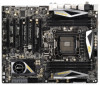
for backup purpose, without written consent of ASRock Inc. Products and corporate names appearing in this guide may or may not be registered trademarks or ASRock Website: http://www.asrock.com Published October 2011 Copyright©2011 ASRock INC. All rights reserved. 1 ASRock X79 Extreme7 Motherboard - ASRock X79 Extreme7 | Quick Installation Guide - Page 2
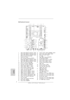
46 PCI Slot (PCI1, Black) 24 Intel X79 Chipset 47 PCI Express 3.0 x16 Slot (PCIE2, Black) 25 Chassis Fan Connector (CHA_FAN2) 48 PCI Express 3.0 x16 Slot (PCIE1, Black) 26 Reset Switch (RSTBTN) 49 SLI / XFIRE Power Connector 27 Power Switch (PWRBTN) 2 ASRock X79 Extreme7 Motherboard English - ASRock X79 Extreme7 | Quick Installation Guide - Page 3
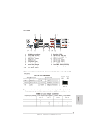
speaker you use. TABLE for Audio Output Connection Audio Output Channels Front Speaker Rear Speaker Central / Bass Side Speaker (No. 10) (No. 7) (No. 8) (No. 6) 2 V -- -- -- 4 V V -- -- 6 V V V -- 8 V V V V English 3 ASRock X79 Extreme7 Motherboard - ASRock X79 Extreme7 | Quick Installation Guide - Page 4
Primary output" to use Rear Speaker, Central/Bass, and Front Speaker, or select "Realtek HDA Audio 2nd output" to use front panel audio. *** eSATA3 connector supports SATA Gen3 in cable 1M. English 4 ASRock X79 Extreme7 Motherboard - ASRock X79 Extreme7 | Quick Installation Guide - Page 5
ASRock Reminds You... To get better performance in Windows® 7 / 7 64-bit / VistaTM / VistaTM 64bit, it is recommended to set the BIOS option in Storage Configuration to AHCI mode. For the BIOS setup, please refer to the "User Manual" in our support CD for details. 5 ASRock X79 Extreme7 Motherboard - ASRock X79 Extreme7 | Quick Installation Guide - Page 6
Series Processors in Socket LGA 2011 - Digi Power Design - Advanced V12 + 2 Power Phase Design - Supports Intel® Turbo Boost 2.0 Technology - Supports Hyper-Threading Technology (see CAUTION 1) - Supports Untied Overclocking Technology - Intel® X79 - Quad Channel DDR3 Memory Technology (see CAUTION - ASRock X79 Extreme7 | Quick Installation Guide - Page 7
CAUTION 6) - 2 x SATA3 6.0 Gb/s connectors by Intel® X79, support RAID (RAID 0, RAID 1, RAID 5, RAID 10 and Intel Rapid Storage 3.0), NCQ, AHCI and "Hot Plug" functions connector - Front panel audio connector - 3 x USB 2.0 headers (support 6 USB 2.0 ports) 7 ASRock X79 Extreme7 Motherboard English - ASRock X79 Extreme7 | Quick Installation Guide - Page 8
BIOS with GUI support - Supports "Plug and Play" - ACPI 1.1 Compliance Wake Up Events - Supports jumperfree - SMBIOS 2.3.1 Support - CPU, VCCSA, DRAM, VTT, CPU PLL, PCH1.1V, PCH1.5V Voltage Multi-adjustment - Drivers (see CAUTION 19) - FCC, CE, WHQL English 8 ASRock X79 Extreme7 Motherboard - ASRock X79 Extreme7 | Quick Installation Guide - Page 9
overclocking. CAUTION! 1. About the setting of "Hyper Threading Technology", please check page 68 of "User Manual" in the support CD. 2. This motherboard supports Quad Channel Memory Technology. Before you implement Quad Channel Memory Technology, make sure to read the installation guide of memory - ASRock X79 Extreme7 | Quick Installation Guide - Page 10
ASRock Extreme Tuning Utility (AXTU). ASRock website: http://www.asrock.com 8. ASRock Instant Flash is a BIOS flash utility embedded in Flash ROM. This convenient BIOS update tool allows you to update system BIOS data streams you are transferring currently. 10 ASRock X79 Extreme7 Motherboard English - ASRock X79 Extreme7 | Quick Installation Guide - Page 11
ASRock XFast RAM is a new function that is included into ASRock Extreme Tuning Utility (AXTU). It fully utilizes the memory space that cannot be used under Windows® OS 32-bit CPU. ASRock 19. Intel Rapid Storage Technology enterprise 3.0 is not supported by ASRock X79 Extreme7 Motherboard English - ASRock X79 Extreme7 | Quick Installation Guide - Page 12
you insert the 2011-Pin CPU into the socket, please check if the CPU surface is unclean or if there are any bent pins in the socket. Do not force to insert the CPU into the socket if above situation is found. Otherwise, the CPU will be seriously damaged. English 12 ASRock X79 Extreme7 Motherboard - ASRock X79 Extreme7 | Quick Installation Guide - Page 13
key notches. orientation key notch Pin1 alignment key English orientation key notch 2011-Pin CPU alignment key 2011-Pin Socket For proper inserting, please ensure to match the four orientation key notches of the CPU with the four alignment keys of the socket. 13 ASRock X79 Extreme7 Motherboard - ASRock X79 Extreme7 | Quick Installation Guide - Page 14
returning the motherboard for after service. Step 3-2. Press down the right load lever, and secure it with the load plate tab under the retention tab. Step 3-3. Press down the left load lever, and secure it with the load plate tab under the retention tab. 14 ASRock X79 Extreme7 Motherboard English - ASRock X79 Extreme7 | Quick Installation Guide - Page 15
, the heatsink cannot be secured on the motherboard. Step 5. Connect fan header with the CPU fan connector on the motherboard. Step 6. Secure excess cable with tie-wrap to ensure the cable does not interfere with fan operation or contact other components. English 15 ASRock X79 Extreme7 Motherboard - ASRock X79 Extreme7 | Quick Installation Guide - Page 16
is activated. If four memory modules are installed in the DDR3 DIMM slots, then Quad Channel Memory Technology is activated. 3. It is not allowed to install a DDR or DDR2 memory module into DDR3 slot; otherwise, this motherboard and DIMM may be damaged. 16 ASRock X79 Extreme7 Motherboard English - ASRock X79 Extreme7 | Quick Installation Guide - Page 17
permanent damage to the motherboard and the DIMM if you force the DIMM into the slot at incorrect orientation. Step 3. Firmly insert the DIMM into the slot until the retaining clips at both ends fully snap back in place and the DIMM is properly seated. 17 ASRock X79 Extreme7 Motherboard English - ASRock X79 Extreme7 | Quick Installation Guide - Page 18
Intel® Socket 2011 Sandy Bridge-E Processor doesn't support PCIE 3.0, but this motherboard is already PCIE 3.0 hardware ready. It depends on Intel's CPU to enable PCIE 3.0. Please check Intel's website for information on future CPU updates and releases. English 18 ASRock X79 Extreme7 Motherboard - ASRock X79 Extreme7 | Quick Installation Guide - Page 19
for the card before you start the installation. Step 2. Remove the system unit cover (if your motherboard is already installed in a chassis). Step 3. Remove the bracket facing the slot that you intend chassis with screws. Step 6. Replace the system cover. 19 ASRock X79 Extreme7 Motherboard English - ASRock X79 Extreme7 | Quick Installation Guide - Page 20
® certified. 2. Make sure that your graphics card driver supports NVIDIA® SLITM technology (driver version 280.41 and later). Download the driver from NVIDIA website (www.nvidia.com). 3. Make sure auxiliary power source to the PCI Express graphics cards. 20 ASRock X79 Extreme7 Motherboard English - ASRock X79 Extreme7 | Quick Installation Guide - Page 21
ngers on each graphics card. Make sure the ASRock SLI_Bridge_2S Card is firmly in place. ASRock SLI_Bridge_2S Card Step4. Connect a VGA cable or a DVI cable to the monitor connector or the DVI connector of the graphics card that is inserted to PCIE1 slot. English 21 ASRock X79 Extreme7 Motherboard - ASRock X79 Extreme7 | Quick Installation Guide - Page 22
graphics card. Make sure ASRock 3-Way SLI-2S1S Bridge Card is firmly in place. English ASRock 3-Way SLI-2S1S Bridge Card Step4. Connect a VGA cable or a DVI cable to the monitor connector or the DVI connector of the graphics card that is inserted to PCIE1 slot. 22 ASRock X79 Extreme7 Motherboard - ASRock X79 Extreme7 | Quick Installation Guide - Page 23
Installation and Setup Install the graphics card drivers to your system. After that, you can enable the MultiGraphics Processing Unit (GPU) feature in the NVIDIA . And click Apply. C. Reboot your system. D. You can freely enjoy the benefit of SLITM feature. 23 ASRock X79 Extreme7 Motherboard English - ASRock X79 Extreme7 | Quick Installation Guide - Page 24
figuration item, please select Enable SLI. And click Apply. F. Reboot your system. G. You can freely enjoy the benefit of SLITM or Quad SLITM feature. 24 ASRock X79 Extreme7 Motherboard English - ASRock X79 Extreme7 | Quick Installation Guide - Page 25
a registered trademark of NVIDIA® Technologies Inc., and is used only for identification or explanation and to the owners' benefit, without intent to infringe. 25 ASRock X79 Extreme7 Motherboard English - ASRock X79 Extreme7 | Quick Installation Guide - Page 26
the future, please refer to AMD graphics card manuals for detailed installation guide. Step 1. Insert one Radeon graphics card into PCIE1 slot and the other Radeon graphics card to PCIE3 slot. Make sure that the cards are properly seated on the slots. English 26 ASRock X79 Extreme7 Motherboard - ASRock X79 Extreme7 | Quick Installation Guide - Page 27
cards. (CrossFire Bridge is provided with the graphics card you purchase, not bundled with this motherboard. Please refer to your graphics card vendor for details.) CrossFire Bridge or Step 3. Connect D-Sub monitor cable to the DVI to D-Sub adapter.) English 27 ASRock X79 Extreme7 Motherboard - ASRock X79 Extreme7 | Quick Installation Guide - Page 28
slots. (CrossFireTM Bridge is provided with the graphics card you purchase, not bundled with this motherboard. Please refer to your graphics card vendor for details.) CrossFireTM Bridge Step 5. Connect the Sub monitor cable to the DVI to D-Sub adapter.) English 28 ASRock X79 Extreme7 Motherboard - ASRock X79 Extreme7 | Quick Installation Guide - Page 29
drivers prior to installation. Please check AMD website for ATITM driver updates. Step 3. Step 4. Step 5. Install the required drivers to your system. For Windows® XP OS: A. AMD recommends Windows® XP Service (if you install three Radeon graphics cards). English 29 ASRock X79 Extreme7 Motherboard - ASRock X79 Extreme7 | Quick Installation Guide - Page 30
Display upgrade. With the external add-on PCI Express VGA cards, you can easily enjoy the benefits of Surround Display feature. For detailed instructions, please refer to the document at the following path in the Support CD: ..\ Surround Display Information 30 ASRock X79 Extreme7 Motherboard English - ASRock X79 Extreme7 | Quick Installation Guide - Page 31
Multi-Angle CIR Receiver does not support Hot-Plug function. Please install it before you boot the system. * ASRock Smart Remote is only supported by some of ASRock motherboards. Please refer to ASRock website for the motherboard support list: http://www.asrock.com 31 ASRock X79 Extreme7 Motherboard - ASRock X79 Extreme7 | Quick Installation Guide - Page 32
Guide ASRock refer to below instruction for proper operation. This motherboard provides two USB ports for ASRock XFast Charger: ASRock XFast Charger feature, you can freely enjoy the quick charging convenience by installing the USB cable on these two ports. English 32 ASRock X79 Extreme7 Motherboard - ASRock X79 Extreme7 | Quick Installation Guide - Page 33
after you update the BIOS. If you need to clear the CMOS when you just finish updating the BIOS, you must boot GUID and MAC address will be cleared only if the CMOS battery is removed. The Clear CMOS Switch has the same function as the Clear CMOS jumper. English 33 ASRock X79 Extreme7 Motherboard - ASRock X79 Extreme7 | Quick Installation Guide - Page 34
ATA2 (SATA2) connectors support SATA data cables for internal motherboard. Please connect the black end of SATA power cable to the power connector on each drive. Then connect the white end of SATA power cable to the power connector of the power supply. English 34 ASRock X79 Extreme7 Motherboard - ASRock X79 Extreme7 | Quick Installation Guide - Page 35
1 GND IRRX Consumer Infrared Module Header (4-pin CIR1) (see p.2 No. 37) 1 GND IRTX IRRX ATX+5VSB This header supports an optional wireless transmitting and receiving infrared module. This header can be used to connect the remote controller receiver. English 35 ASRock X79 Extreme7 Motherboard - ASRock X79 Extreme7 | Quick Installation Guide - Page 36
. 1. High Definition Audio supports Jack Sensing, but the panel wire on the chassis must support HDA to function correctly. Please follow the instruction in our manual and chassis manual to install your system. 2. system is in S3/S4 sleep state or powered off (S5). 36 ASRock X79 Extreme7 Motherboard - ASRock X79 Extreme7 | Quick Installation Guide - Page 37
the fan cables to the fan connectors and match the black wire to the ground pin. CHA_FAN1, CHA_FAN2 and CHA_FAN3 support FAN control. SB_FAN1 supports Quiet FAN. Please connect the CPU fan cable to the connector and match the black wire to the ground pin. 37 ASRock X79 Extreme7 Motherboard English - ASRock X79 Extreme7 | Quick Installation Guide - Page 38
) support, the 3-Pin CPU fan still can work successfully even without the fan speed control function. If you plan to connect the 3-Pin CPU fan to the CPU fan connector on this motherboard, please when two graphics cards are plugged to this motherboard. English 38 ASRock X79 Extreme7 Motherboard - ASRock X79 Extreme7 | Quick Installation Guide - Page 39
, there is one IEEE 1394 header (FRONT_1394) on this motherboard. This IEEE 1394 header can support one IEEE 1394 port. This COM1 header supports a serial port module. HDMI_SPDIF Header (2-pin HDMI_SPDIF1) (see connector of HDMI VGA card to this header. English 39 ASRock X79 Extreme7 Motherboard - ASRock X79 Extreme7 | Quick Installation Guide - Page 40
into the USB 3.0 header (USB3_2_3 or USB3_4_5) on the motherboard. Step 6 The Front USB 3.0 Panel is ready to use. English The Installation Guide of Rear USB 3.0 Bracket Step 1 Unscrew the two screws from Step 4 Put the rear USB 3.0 bracket into the chassis. 40 ASRock X79 Extreme7 Motherboard - ASRock X79 Extreme7 | Quick Installation Guide - Page 41
2.12 Smart Switches The motherboard has three smart switches: power switch, reset switch and clear CMOS switch, allowing users to quickly turn on/ p.3 No. 18) clr CMOS Clear CMOS Switch is a smart switch, allowing users to quickly clear the CMOS values. English 41 ASRock X79 Extreme7 Motherboard - ASRock X79 Extreme7 | Quick Installation Guide - Page 42
-memory initialization. Cache initialization CPU post-memory initialization. Application Processor(s) (AP) initialization CPU post-memory initialization. Boot Strap Processor (BSP) selection CPU post-memory initialization. System Management Mode (SMM) initialization ASRock X79 Extreme7 Motherboard - ASRock X79 Extreme7 | Quick Installation Guide - Page 43
Memory initialization error. Invalid memory size or memory modules do not match Memory initialization error. No usable memory detected Unspecified memory initialization error Memory not installed Invalid CPU type or Speed CPU mismatch CPU self test English 43 ASRock X79 Extreme7 Motherboard - ASRock X79 Extreme7 | Quick Installation Guide - Page 44
0xA1 0xA2 0xA3 0xA4 0xA5 44 Installation of the South Bridge Runtime Services CPU DXE initialization is started CPU DXE initialization (CPU module specific) Boot Device Selection (BDS) phase is started Driver connecting is started PCI Bus initialization is started PCI ASRock X79 Extreme7 Motherboard - ASRock X79 Extreme7 | Quick Installation Guide - Page 45
(see ASL Status Codes section below) Ready To Boot event Legacy Boot event Exit Boot Services event Runtime Set Virtual Address MAP Begin Runtime Set Virtual Address MAP End Legacy Option ROM Initialization update is failed Reset protocol is not available English 45 ASRock X79 Extreme7 Motherboard - ASRock X79 Extreme7 | Quick Installation Guide - Page 46
Driver Installation Guide To install the drivers to your system, please insert the support CD to your optical drive first. Then, the drivers compatible to your system can be auto-detected and listed on the support CD driver XP / XP 64-bit OS on your system. 46 ASRock X79 Extreme7 Motherboard English - ASRock X79 Extreme7 | Quick Installation Guide - Page 47
"Marvell SATA3 Operation Mode" to [AHCI] for SATA3_M0 to SATA3_M4 ports. STEP 2: Install Windows® 7 / 7 64-bit / VistaTM / VistaTM 64-bit OS on your system. 47 ASRock X79 Extreme7 Motherboard English - ASRock X79 Extreme7 | Quick Installation Guide - Page 48
Function Operation Guide Dual LAN with Teaming function enabled on this motherboard allows two you don't want to use Teaming, please install the LAN driver provided by our support CD link.) 2. From the Teams menu, select Create Team Mode on next start. 48 ASRock X79 Extreme7 Motherboard English - ASRock X79 Extreme7 | Quick Installation Guide - Page 49
to a team where its driver is disabled may negatively affect the offloading capabilities of the team. This may have an impact on the team's performance. Therefore, it is recommended that only driver-enabled network adapters be added as members to a team. 49 ASRock X79 Extreme7 Motherboard English - ASRock X79 Extreme7 | Quick Installation Guide - Page 50
has been correctly performed, a virtual team adapter driver is created for each configured team. * If supported for testing, it is recommended to connect team members to a switch. * Not all network adapters made by others are supported or fully certified for teaming. 50 ASRock X79 Extreme7 Motherboard - ASRock X79 Extreme7 | Quick Installation Guide - Page 51
click Properties. d. Configure the IP address and any other necessary TCP/IP configuration for the team, and then click OK when finished. 51 ASRock X79 Extreme7 Motherboard English - ASRock X79 Extreme7 | Quick Installation Guide - Page 52
during overclocking, but PCI / PCIE buses are in the fixed mode so that BCLK can operate under a more stable overclocking environment. Please refer to the warning on page 9 for the possible overclocking risk before you apply Untied Overclocking Technology. 52 ASRock X79 Extreme7 Motherboard English - ASRock X79 Extreme7 | Quick Installation Guide - Page 53
your computer. If the Main Menu does not appear automatically, locate and double-click on the file "ASSETUP.EXE" from the BIN folder in the Support CD to display the menus. 53 ASRock X79 Extreme7 Motherboard English - ASRock X79 Extreme7 | Quick Installation Guide - Page 54
ötigen, besuchen Sie bitte unsere Webseite: www.asrock.com/support/index.asp 1.1 Kartoninhalt ASRock X79 Extreme7 Motherboard (ATX-Formfaktor: 30.5 cm x 24.4 cm; 12.0 Zoll x 9.6 Zoll) ASRock X79 Extreme7 Schnellinstallationsanleitung ASRock X79 Extreme7 Support-CD Sechs Serial ATA (SATA) -Datenkabel - ASRock X79 Extreme7 | Quick Installation Guide - Page 55
mit Prozessoren der Intel® Workstation 1S Xeon® E5 2xxx- & 4xxx-Serie in Sockel LGA 2011 - Max. Kapazität des Systemspeichers: 48GB (siehe VORSICHT 4) - Unterstützt Intel® Extreme Memory Profile ( Ethernet 802.3az - Unterstützt duales LAN mit Teamfunktion 55 ASRock X79 Extreme7 Motherboard Deutsch - ASRock X79 Extreme7 | Quick Installation Guide - Page 56
SATA2 3,0 GB/s-Anschlüsse, unterstützen RAID- (RAID 0, RAID 1, RAID 5, RAID 10 und Intel Rapid Storage 3.0), NCQ-, AHCI-und „Hot Plug" (Hot-Plugging)-Funktionen - 7 x SATA3 6,0 GB x IEEE 1394-Anschluss - 1 x Betriebs-LED-Header - CPU/Gehäuse/Strom/SB lüfter-Anschluss ASRock X79 Extreme7 Motherboard - ASRock X79 Extreme7 | Quick Installation Guide - Page 57
(Reset) mit LED - 64Mb AMIs Legal BIOS UEFI mit GUI-Unterstützung - Unterstützung ASRock U-COP (siehe VORSICHT 18) - Boot Failure Guard (B.F.G. - Systemstartfehlerschutz) - Gute Nacht-LED - Überwachung der CPU-Temperatur - Motherboardtemperaturerkennung Deutsch 57 ASRock X79 Extreme7 Motherboard - ASRock X79 Extreme7 | Quick Installation Guide - Page 58
asrock.com WARNUNG Beachten Sie bitte, dass Overclocking, einschließlich der Einstellung im BIOS, Anwenden der Untied Overclocking Einschränkung nicht. Sie können ASRock XFast RAM zur Nutzung des Speichers, den Windows® nicht verwenden kann, einsetzen. 58 ASRock X79 Extreme7 Motherboard Deutsch - ASRock X79 Extreme7 | Quick Installation Guide - Page 59
iPhone wesentlich schneller über einen Computerauf - genaugenommen bis zu 40 % schneller als zuvor. Der ASRock APP Charger ermöglicht Ihnen die schnelle Aufladung mehrerer Apple-Geräte gleichzeitig; der Ladevorgang wird sogar dann fortgesetzt, wenn der PC 59 ASRock X79 Extreme7 Motherboard Deutsch - ASRock X79 Extreme7 | Quick Installation Guide - Page 60
Temperatur erreicht. Normalerweise bleibt ASRock X-FAN deaktiviert, damit Benutzer eine möglichst geräuscharme Computererfahrung genießen können. Zieltemperatur und Lüftergeschwindigkeitseinstellungen können im UEFIEinrichtungsprogramm konfiguriert werden. 60 ASRock X79 Extreme7 Motherboard Deutsch - ASRock X79 Extreme7 | Quick Installation Guide - Page 61
BIOS-Dateien zuerst im Stammverzeichnis Ihres USB-Datenträgers platziert werden müssen. Diese Funktion wird nur von USB 2.0-Ports unterstützt. 17. Obwohl dieses Motherboard stufenlose Steuerung bietet, wird Overclocking ühen. 19. Intel Rapid Storage Technology ASRock X79 Extreme7 Motherboard Deutsch - ASRock X79 Extreme7 | Quick Installation Guide - Page 62
nach der BIOS-Aktualisierung löschen. Wenn Sie das CMOS nach Abschluss der BIOS-Aktualisierung lö GUID und MAC-Adresse nur gelöscht werden, wenn die CMOS-Batterie entfernt wird. Der CMOS löschen-Schalter hat dieselbe Funktion wie der CMOS löschen-Jumper. Deutsch 62 ASRock X79 Extreme7 Motherboard - ASRock X79 Extreme7 | Quick Installation Guide - Page 63
diese Header und Anschlüsse. Wenn Sie Jumperkappen auf Header und Anschlüsse setzen, wird das Motherboard unreparierbar beschädigt! Seriell-ATA2-Anschlüsse (SATA2_0_1: siehe S.2 - No. 19) (SATA2_2_3 SATAStromversorgungskabels mit dem Stromanschluss des Netzteils. 63 ASRock X79 Extreme7 Motherboard - ASRock X79 Extreme7 | Quick Installation Guide - Page 64
sechs üblichen USB 2.0-Ports an den I/O-Anschlüssen befinden sich drei USB 2.0Anschlussleisten am Motherboard. Pro USB 2.0Anschlussleiste werden zwei USB 2.0-Ports unterstützt. USB 3.0-Header (19-pol. USB3_2_3 Header kann zum Anschließen RemoteEmpfänger. Deutsch 64 ASRock X79 Extreme7 Motherboard - ASRock X79 Extreme7 | Quick Installation Guide - Page 65
ßen der Reset-Taste an der Frontblende des Gehäuses. Mit der Reset-Taste können Sie den Computer im Falle eines Absturzes neu starten. 65 ASRock X79 Extreme7 Motherboard - ASRock X79 Extreme7 | Quick Installation Guide - Page 66
CHA_FAN_SPEED gesteuert werden. CHA_FAN1-, CHA_FAN2- und CHA_FAN3- unterstützen Lüftersteuerung. (3-pin PWR_FAN1) (siehe S.2 - No. 11) 66 GND +12V PWR_FAN_SPEED SB_FAN1 unterstützt geräuscharmen Lüfter. ASRock X79 Extreme7 Motherboard Deutsch - ASRock X79 Extreme7 | Quick Installation Guide - Page 67
. 12) 12 24 Verbinden Sie die ATXStromversorgung mit diesem Header. 1 13 Obwohl dieses Motherboard einen 24-pol. ATX- 12 24 Stromanschluss bietet, kann es auch mit einem modifi 5 ein. 8 5 Installation der 4-Pin ATX 12V Energieversorgung 4 ASRock X79 Extreme7 Motherboard 1 67 Deutsch - ASRock X79 Extreme7 | Quick Installation Guide - Page 68
ssen diesen Anschluss nicht zwingend verwenden. Wenn allerdings zwei Grafikkarten gleichzeitig am Motherboard angeschlossen sind, verbinden Sie diesen Anschluss bitte mit einem Festplatten-Stromversorgungsstecker. Au der HDMI-VGA-Karte mit diesem Anschluss. Deutsch 68 ASRock X79 Extreme7 Motherboard - ASRock X79 Extreme7 | Quick Installation Guide - Page 69
die USB 3.0-Frontblende mit sechs Gehäuseschrauben am Festplatteneinschub. Schritt 5 Schließen Sie das Kabel der USB 3.0-Frontblende am USB 3.0-Header (USB3_2_3 oder USB3_4_5) am Motherboard an. Schritt 6 Die USB 3.0-Frontblende ist nun einsatzbereit. Deutsch 69 ASRock X79 Extreme7 Motherboard - ASRock X79 Extreme7 | Quick Installation Guide - Page 70
USB 3.0-Blech an der Rückwand des Gehäuses ein. 1.5 Schnellschalter Dieses Motherboard besitzt drei Schnellschalter: Netzschalter, Rücksetzschalter (Reset) und CMOS löschen-Schalter, Schnellschalter, mit dem Benutzer die CMOS-Werte schnell löschen können. 70 ASRock X79 Extreme7 Motherboard Deutsch - ASRock X79 Extreme7 | Quick Installation Guide - Page 71
der Support-CD, um die Menüs aufzurufen. Das Setup-Programm soll es Ihnen so leicht wie möglich machen. Es ist menügesteuert, d.h. Sie können in den verschiedenen Untermenüs Ihre Auswahl treffen und die Programme werden dann automatisch installiert. 71 ASRock X79 Extreme7 Motherboard Deutsch - ASRock X79 Extreme7 | Quick Installation Guide - Page 72
sous Windows® 7 / 7 64 bits / VistaTM / VistaTM 64 bits, il est recommandé de paramétrer l'option BIOS dans Configuration de stockage en mode AHCI. Pour plus de détails sur l'installation BIOS, référez-vous au "Mode d'emploi" sur votre CD de support. 72 ASRock X79 Extreme7 Motherboard Français - ASRock X79 Extreme7 | Quick Installation Guide - Page 73
38xx sur Socket LGA 2011 - Conception Digi Power - Conception avancée V12 + 2 Power Phase - Prend en charge la technologie Intel® Turbo Boost 2.0 - Prise en charge de la technologie Hyper-Threading (voir ATTENTION 1) - Prend en charge la technologie Untied Overclocking - Intel® X79 - Technologie de - ASRock X79 Extreme7 | Quick Installation Guide - Page 74
jusqu'à 5 Gb/s - 4 x connecteurs SATA2, prennent en charge un taux de transfert de données pouvant aller jusqu'à 3.0Go/s, supporte RAID (RAID 0, RAID 1, RAID 5, RAID 10 et Intel Rapid Storage 3.0), NCQ, AHCI et « Hot Plug » (Branchement à chaud) Français 74 ASRock X79 Extreme7 Motherboard - ASRock X79 Extreme7 | Quick Installation Guide - Page 75
Boot - ASRock Instant Flash (voir ATTENTION 8) - Chargeur ASRock APP (voir ATTENTION 9) - ASRock SmartView (voir ATTENTION 10) - ASRock XFast USB (voir ATTENTION 11) - ASRock XFast LAN (voir ATTENTION 12) - Chargeur XFast ASRock (voir ATTENTION 13) Français 75 ASRock X79 Extreme7 Motherboard - ASRock X79 Extreme7 | Quick Installation Guide - Page 76
effectuer l'overclocking, y compris ajuster les réglages du BIOS, appliquer la technologie Untied Overclocking, ou utiliser des outils de tiers pour l'overclocking. L'overclocking peut affecter des dommages possibles causés par l'overclocking. Français 76 ASRock X79 Extreme7 Motherboard - ASRock X79 Extreme7 | Quick Installation Guide - Page 77
supporte guide d'installation des modules mémoire en page 16 pour réaliser une installation correcte. 3. Grâce aux spécifications du processeur Intel Overclocking, vous pouvez overclocker ASRock Extreme Tuning Utility (AXTU). Site Web de ASRock : http://www.asrock.com 77 ASRock X79 Extreme7 Motherboard - ASRock X79 Extreme7 | Quick Installation Guide - Page 78
le navigateur IE8. Site Internet ASRock : http://www.asrock.com/Feature/SmartView/index. asp 11. ASRock XFast USB permet d'améliorer les performances de votre périphérique de stockage USB. Les performances réelles dépendent des propriétés du périphérique. 78 ASRock X79 Extreme7 Motherboard Français - ASRock X79 Extreme7 | Quick Installation Guide - Page 79
la page 32. 14. ASRock XFast RAM est une nouvelle fonction intégrée à l'utilitaire ASRock Extreme Tuning Utility (AXTU). Il de configuration UEFI. 16. ASRock Crashless BIOS permet aux utilisateurs de mettre à jour leur BIOS sans qu'ils aient à craindre un ASRock X79 Extreme7 Motherboard Français - ASRock X79 Extreme7 | Quick Installation Guide - Page 80
conforme à la norme EuP, une carte mère EuP et une alimentation EuP sont requises. Selon les suggestions d'Intel', l'alimentation électrique EuP doit correspondre à la norme, qui est que l'efficacité électrique de 5v en de courant pour plus de détails. 80 ASRock X79 Extreme7 Motherboard Français - ASRock X79 Extreme7 | Quick Installation Guide - Page 81
le BIOS. Si vous avez besoin d'effacer le CMOS après avoir mis à jour le BIOS, vous GUID et l'adresse MAC seront effacés seulement si la batterie du CMOS est enlevée. Le commutateur Effacer CMOS présente la même fonction que le cavalier Effacer CMOS. Français 81 ASRock X79 Extreme7 Motherboard - ASRock X79 Extreme7 | Quick Installation Guide - Page 82
sur le connecteur d'alimentation sur chaque unité. Connectez ensuite l'extrémité blanche du cordon d'alimentation SATA sur le connecteur d'alimentation de l'unité d'alimentation électrique. 82 ASRock X79 Extreme7 Motherboard - ASRock X79 Extreme7 | Quick Installation Guide - Page 83
(IR1 br.5) (voir p.2 No. 39) IRTX +5VSB DUMMY 1 GND IRRX Cet en-tête supporte un module infrarouge optionnel de transfert et de réception sans fil. Barrette pour module à infrarouges grand modules à infrarouges grand public, comme chaînes hi-fi, décodeurs, etc. 83 ASRock X79 Extreme7 Motherboard - ASRock X79 Extreme7 | Quick Installation Guide - Page 84
de panneau sur le châssis doit prendre en charge le HDA pour fonctionner correctement. Veuillez suivre les instructions dans notre manuel et le manuel de châssis afin installer votre système. 2. Si vous utilisez se bloque ou s'il n'arrive pas à redémarrer normalement. 84 ASRock X79 Extreme7 Motherboard - ASRock X79 Extreme7 | Quick Installation Guide - Page 85
en charge la fonction contrôle du ventilateur. SB_FAN1 prend en charge la fonction ventilateur silencieux. (SB_FAN1 br. 3) GND (voir p.2 No. 17) +12V SB_FAN_SPEED 85 ASRock X79 Extreme7 Motherboard Français - ASRock X79 Extreme7 | Quick Installation Guide - Page 86
brancher le fil noir sur la broche de terre. Bien que cette carte mère offre un support de (Ventilateur silencieux ventilateur de CPU à 4 broches , le ventilateur de CPU à 3 broches broche 5. 8 5 4-Installation d'alimentation à 4 broches ATX 12V 4 1 86 ASRock X79 Extreme7 Motherboard Français - ASRock X79 Extreme7 | Quick Installation Guide - Page 87
I/O, il y a un header de IEEE1394 (FRONT_1394) sur cette carte mere. Le header de IEEE 1394 peut supporter un port de IEEE 1394. Cette en-tête de port COM est utilisée pour prendre en charge un module de HDMI_SPDIF de la carte VGA HDMI sur ce connecteur. Français 87 ASRock X79 Extreme7 Motherboard - ASRock X79 Extreme7 | Quick Installation Guide - Page 88
frontal peut maintenant être utilisé. Français Le Guide d'installation du Support arrière USB 3.0 Étape 1 Dévissez support arrière USB 3.0. Étape 3 Vissez les deux vis dans le support arrière USB 3.0. Étape 4 Placez le support arrière USB 3.0 dans le châssis. 88 ASRock X79 Extreme7 Motherboard - ASRock X79 Extreme7 | Quick Installation Guide - Page 89
réinitialiser rapidement le système. L'interrupteur d'effacement de CMOS est un interrupteur rapide qui permet à l'utilisateur d'effacer rapidement les valeurs du CMOS. Français 89 ASRock X79 Extreme7 Motherboard - ASRock X79 Extreme7 | Quick Installation Guide - Page 90
détaillées sur le BIOS, veuillez consulter le Guide de l'utilisateur (fichier PDF) dans le CD technique. 3. Informations sur le CD de support Cette carte mère supporte divers systèmes d'exploitation BIN et doublecliquez dessus pour afficher les menus. 90 ASRock X79 Extreme7 Motherboard Français - ASRock X79 Extreme7 | Quick Installation Guide - Page 91
/ VistaTM 64-bit, si consiglia di impostare l'opzione BIOS in Storage Configuration (Configurazione di archiviazione) sulla modalità AHCI. Per l'impostazione BIOS, fare riferimento a "User Manual" (Manuale dell'utente) nel CD di supporto per dettagli. 91 ASRock X79 Extreme7 Motherboard Italiano - ASRock X79 Extreme7 | Quick Installation Guide - Page 92
processori Intel® Workstation 1S Xeon® E5 serie 2xxx e 4xxx in socket LGA 2011 - Capacità massima della memoria di sistema: 48GB (vedi ATTENZIONE 4) - Supporto di Intel® XMP (Extreme Memory Profile .3az - Supporta Dual LAN con funzione teaming - Supporta PXE ASRock X79 Extreme7 Motherboard Italiano - ASRock X79 Extreme7 | Quick Installation Guide - Page 93
5Gb/s - 4 x connettori SATA2 3.0Go/s, sopporta RAID (RAID 0, RAID 1, RAID 5, RAID 10 e Intel Rapid Storage 3.0) e delle funzioni NCQ, AHCI e "Hot Plug" - 7 x connettori SATA3 6.0Go/s - alimentazione SLI/XFIRE - Connettore audio sul pannello frontale 93 ASRock X79 Extreme7 Motherboard Italiano - ASRock X79 Extreme7 | Quick Installation Guide - Page 94
UEFI Legal BIOS con Driver, Utilità, Software AntiVirus (versione di prova), CyberLink MediaEspresso 6.5 Trial, Suite software ASRock (Suite multimediale ASRock MAGIX - OEM) - ASRock Extreme Tuning Utility (AXTU) (vedi ATTENZIONE 7) - ASRock Instant Boot - ASRock ASRock X79 Extreme7 Motherboard - ASRock X79 Extreme7 | Quick Installation Guide - Page 95
il collegamento appropriato. 7. L'utilità AXTU (ASRock Extreme Tuning Utility) è uno strumento tutto in uno per regolare varie funzioni del sistema in un'interfaccia facile da usare che include monitoraggio hardware, controllo ventola, overclocking, 95 ASRock X79 Extreme7 Motherboard Italiano - ASRock X79 Extreme7 | Quick Installation Guide - Page 96
bit e che la versione del browser sia IE8. Sito web ASRock: http://www.asrock.com/Feature/SmartView/index.asp 11. ASRock XFast USB può accelerare le prestazioni del dispositivo d'archiviazione USB. Le prestazioni dipendono dalle proprietà del dispositivo. 96 ASRock X79 Extreme7 Motherboard Italiano - ASRock X79 Extreme7 | Quick Installation Guide - Page 97
la dissipazione del calore, ricordare di applicare l'apposita pasta siliconica tra il processore e il dissipatore quando si installa il sistema. 19. Intel Rapid Storage Technology Enterprise 3.0 non è supportato da Microsoft® Windows® XP / XP 64-bit. 97 ASRock X79 Extreme7 Motherboard Italiano - ASRock X79 Extreme7 | Quick Installation Guide - Page 98
norma EuP sono necessari un alimentatore e una scheda elettrica predisposti EuP. In base ai suggerimenti Intel l'alimentatore predisposto EuP deve soddisfare lo standard secondo cui l'efficienza energetica in standby di ulteriori dettagli con il produttore. 98 ASRock X79 Extreme7 Motherboard Italiano - ASRock X79 Extreme7 | Quick Installation Guide - Page 99
il BIOS. Se si deve azzerare la CMOS quando si è completato l'aggiornamento del BIOS, GUID e indirizzo MAC saranno cancellati solo se è rimossa la batteria della CMOS. L'interruttore Clear CMOS (Cancella CMOS) ha la stessa funzione del jumper Clear CMOS. Italiano 99 ASRock X79 Extreme7 Motherboard - ASRock X79 Extreme7 | Quick Installation Guide - Page 100
di alimentazione SATA al connettore di alimentazione del drive. Poi connettete l'estremità bianca del cavo di alimentazio ne SATA al connettore power dell'alimentatore. 100 ASRock X79 Extreme7 Motherboard - ASRock X79 Extreme7 | Quick Installation Guide - Page 101
) 1 GND IRTX IRRX ATX+5VSB Questo connettore può essere utilizzato per collegare dispositivi all'infrarosso consumer, come ad esempio apparecchiature HI-FI, TV, ecc. 101 ASRock X79 Extreme7 Motherboard - ASRock X79 Extreme7 | Quick Installation Guide - Page 102
Audio) per far sì che questa operi in modo corretto. Attenersi alle istruzioni del nostro manuale e del manuale del telaio per installare il sistema. 2. Se si utilizza un pannello audio AC'97, se il computer si blocca e non riesce ad eseguire un normale riavvio. ASRock X79 Extreme7 Motherboard - ASRock X79 Extreme7 | Quick Installation Guide - Page 103
pin di terra. CHA_FAN1, CHA_FAN2 e CHA_FAN3 supportano la funzione Fan Control. SB_FAN1 supporta la funzione Quiet Fan. (3-pin SB_FAN1) (vedi p.2 Nr. 17) GND +12V SB_FAN_SPEED ASRock X79 Extreme7 Motherboard 103 Italiano - ASRock X79 Extreme7 | Quick Installation Guide - Page 104
ATX 12V. Per usare tale fornitura elettrica 4-pin ATX 12V, prego collegare la presa elettrica al Pin 1 e Pin 5. 8 5 Installazione elettrica 4-Pin ATX 12V 4 1 Italiano 104 ASRock X79 Extreme7 Motherboard - ASRock X79 Extreme7 | Quick Installation Guide - Page 105
VGA, consente al sistema di collegare dispositivi per TV digitale HDMI/proiettori/ LCD . Collegare il connettore HDMI_SPDIF della scheda VGA HDMI a questo header. Italiano 105 ASRock X79 Extreme7 Motherboard - ASRock X79 Extreme7 | Quick Installation Guide - Page 106
cavo USB 3.0 e il supporto USB 3.0 posteriore. Punto 3 Avvitare le due viti nel supporto USB 3.0 Punto 4 Inserire il supporto USB 3.0 posteriore. posteriore nel telaio. Italiano 106 ASRock X79 Extreme7 Motherboard - ASRock X79 Extreme7 | Quick Installation Guide - Page 107
agli utenti di resettare rapidamente il sistema. L'interruttore di pulizia CMOS è un interruttore rapido che consente agli utenti di cancellare velocemente i valori CMOS. Italiano 107 ASRock X79 Extreme7 Motherboard - ASRock X79 Extreme7 | Quick Installation Guide - Page 108
BIOS La Flash Memory sulla scheda madre contiene le Setup Utility. Quando si avvia il computer, premi o durante il Power-On-Self-Test (POST) della Setup utility del BIOS; altrimenti, POST continua con i suoi test di routine. Per entrare il BIOS 108 ASRock X79 Extreme7 Motherboard Italiano - ASRock X79 Extreme7 | Quick Installation Guide - Page 109
/ VistaTM 64 bits, es recomendable establecer la opción del BIOS de la configuración de almacenamiento en el modo AHCI. Para obtener detalles sobre la configuración del BIOS, consulte el "Manual del usuario" que se encuentra en nuestro CD de soporte. 109 ASRock X79 Extreme7 Motherboard Español - ASRock X79 Extreme7 | Quick Installation Guide - Page 110
con procesadores Intel® Workstation 1S Xeon® de la serie E5 2xxx y 4xxx en zócalo LGA 2011 - Máxima capacidad de la memoria del sistema: 48GB (vea ATENCIÓN 4) - Compatible con Intel® Extreme Memory Profile energético - Admite LAN dual con la función de equipo ASRock X79 Extreme7 Motherboard Español - ASRock X79 Extreme7 | Quick Installation Guide - Page 111
ver ATENCIÓN 6) - 2 x conectores SATA3 de 6,0 Gb/s con chip Intel® X79 con funciones RAID (RAID 0, RAID 1, RAID 5, RAID 10 y Intel Rapid Storage 3.0), NCQ, AHCI y de "Hot Plug" (conexión en consumidor - 1x En-tête de port COM - 1 x cabecera HDMI_SPDIF 111 ASRock X79 Extreme7 Motherboard Español - ASRock X79 Extreme7 | Quick Installation Guide - Page 112
- ASRock XFast RAM (vea ATENCIÓN 14) - ASRock X-FAN (vea ATENCIÓN 15) - ASRock Crashless BIOS (vea ATENCIÓN 16) - Amplificador Híbrido: - Stepless control de frecuencia de CPU (vea ATENCIÓN 17) - ASRock U-COP (vea ATENCIÓN 18) - Protección de Falla de Inicio (B.F.G..) ASRock X79 Extreme7 Motherboard - ASRock X79 Extreme7 | Quick Installation Guide - Page 113
Manual Intel®, el sistema no arrancará si solamente hay instalados dos DIMM en las ranuras DDR3_B2 y DDR3_D2. Instale previamente los módulos de memoria en las ranuras DDR3_B1 y DDR3_D1. Será entonces cuando las ranuras DDR3_B2 y DDR3_D2 funcionen correctamente. 113 ASRock X79 Extreme7 Motherboard - ASRock X79 Extreme7 | Quick Installation Guide - Page 114
actualizar el BIOS con sólo pulsar un par de botones, sin necesidad de preparar un disco flexible adicional ni utilizar complicadas utilidades de programación. Recuerde que la unidad flash USB o disco duro utilizado debe disponer del sistema de archivos FAT32/16/12. ASRock X79 Extreme7 Motherboard - ASRock X79 Extreme7 | Quick Installation Guide - Page 115
32 para obtener más detalles. 14 ASRock XFast RAM es una nueva función incluida en ASRock Extreme Tuning Utility (AXTU). Utiliza completamente ASRock XFast RAM acorta el tiempo de carga de los sitios Web visitados con anterioridad, lo que permite navegar por Internet ASRock X79 Extreme7 Motherboard - ASRock X79 Extreme7 | Quick Installation Guide - Page 116
energía durante el proceso de actualización del BIOS, ASRock Crashless BIOS finalizará de manera automática el proceso ón que cumplan con la directiva EuP. Según las directrices de Intel, una fuente de alimentación que cumpla con la directiva EuP debe ASRock X79 Extreme7 Motherboard Español - ASRock X79 Extreme7 | Quick Installation Guide - Page 117
el BIOS. Si necesita borrar la memoria CMOS justamente después de actualizar el BIOS, debe GUID 1394 y la dirección MAC solamente se borrará si la batería CMOS se quita. El conmutador Borrar CMOS tiene la misma función que el puente Borrar CMOS. Español 117 ASRock X79 Extreme7 Motherboard - ASRock X79 Extreme7 | Quick Installation Guide - Page 118
de energía de la unidad. A continuación, conecte el extremo blanco del cable de alimentación SATA a la conexión de alimentación de la fuente de alimentación. 118 ASRock X79 Extreme7 Motherboard - ASRock X79 Extreme7 | Quick Installation Guide - Page 119
Esta base de conexiones se puede utilizar para conectar dispositivos infrarrojos del consumidor opcionales, como por ejemplo equipos HI-FI, descodificadores de TV, etc. ASRock X79 Extreme7 Motherboard 119 - ASRock X79 Extreme7 | Quick Installation Guide - Page 120
panel en el chasis debe soportar HDA para operar correctamente. Por favor, siga las instrucciones en nuestro manual y en el manual de chasis para instalar su sistema. 2. Si utiliza el panel de sonido AC'97, instá equipo si se bloquea y no se reinicia con normalidad. ASRock X79 Extreme7 Motherboard - ASRock X79 Extreme7 | Quick Installation Guide - Page 121
ventilador, haciendo coincidir el cable negro con la patilla de masa. CHA_FAN1, CHA_FAN2 y CHA_FAN3 admiten control de ventilador. SB_FAN1 admite ventilador silencioso. Español 121 ASRock X79 Extreme7 Motherboard - ASRock X79 Extreme7 | Quick Installation Guide - Page 122
ón ATX de 20 Pins 1 13 Cabezal de alimentación ATX 12V 8 (8-pin ATX12V1) (vea p.2, N. 6) 4 Conecte la fuente de 5 alimentación ATX 12V a su 1 cabezal. Español 122 ASRock X79 Extreme7 Motherboard - ASRock X79 Extreme7 | Quick Installation Guide - Page 123
al sistema conectarse a dispositivos de TV Digital HDMI / proyectores / Dispositivos LCD. Conecte el conector HDMI_SPDIF de la tarjeta VGA HDMI a esta cabecera. Español 123 ASRock X79 Extreme7 Motherboard - ASRock X79 Extreme7 | Quick Installation Guide - Page 124
soporte USB 3.0 posterior Paso 1 Desatornille los dos tornillos del panel USB 3.0 frontal. Paso 2 Coloque el cable USB 3.0 el soporte USB 3.0 posterior juntos. Español 124 ASRock X79 Extreme7 Motherboard - ASRock X79 Extreme7 | Quick Installation Guide - Page 125
contenido de la memoria CMOS. El conmutador de encendido es un conmutador rápido que permite al usuario encender / apagar rápidamente el sistema. Español 125 ASRock X79 Extreme7 Motherboard - ASRock X79 Extreme7 | Quick Installation Guide - Page 126
información detallada sobre como configurar la BIOS, por favor refiérase al Manual del Usuario (archivo PDF) contenido en el CD. 3. Información de Software Support CD Esta placa-base soporta diversos tipos archivo "ASSETUP.EXE" para iniciar la instalación. 126 ASRock X79 Extreme7 Motherboard Español - ASRock X79 Extreme7 | Quick Installation Guide - Page 127
1 ASRock X79 Extreme7 ASRock ASRock BIOS ASRock ASRock. ASRock http://www.asrock.com www.asrock.com/support/index.asp 1.1 ASRock X79 Extreme7 ATX: 12,0 x 9,6 30,5 x 24,4 см) ASRock X79 Extreme7 ASRock X79 Extreme7 6 x Serial ATA (SATA 2 - ASRock X79 Extreme7 | Quick Installation Guide - Page 128
Overclocking Intel® X79 Память Quad Channel DDR3 Memory Technology 2) - 6 x DDR3 DIMM 3) DDR3 2400+(OC)/1600/1333/1066/800 не- ECC, DDR3 ECC Intel® Workstation 1S Xeon E5 2xxx и 4xxx LGA 2011 48 ГБ 4) Intel® Extreme Memory 128 ASRock X79 Extreme7 Motherboard - ASRock X79 Extreme7 | Quick Installation Guide - Page 129
RAID 5, RAID 10 и Intel Rapid Storage 3.0), NCQ, AHCI 7 x SATA3 6,0 1 x 1 x 1 x 1 x COM - 1 x HDMI_SPDIF - 1 x IEEE 1394 - 1 x Power LED CPU/Chassis/Power/SB FAN - 24 ATX - 8 ATX 12 SLI/XFIRE 3 x USB 2.0 6 USB 2.0 - 2 x USB 3.0 4 USB 3.0 129 ASRock X79 Extreme7 Motherboard - ASRock X79 Extreme7 | Quick Installation Guide - Page 130
BIOS 16) - Hybrid Booster: 17) - ASRock U-COP 18 Boot Failure Guard (B.F.G LED CPU/Chassis/Power/SB FAN SB 12V, +5V, +3.3V, Vcore Microsoft® Windows® 7 / 7 64-bit / VistaTM 64 VistaTM / XP / XP 64-bit 19) - FCC, CE, WHQL ErP/EuP Ready ErP/EuP 20) ASRock X79 Extreme7 Motherboard - ASRock X79 Extreme7 | Quick Installation Guide - Page 131
64-bit ASRock XFast RAM Windows®. 5 Intel® Socket 2011 Sandy Bridge-E PCIE 3.0 PCIE 3.0 PCIE 3.0 Intel Intel. 6 2-, 4-, 6- и 8 3. 7 ASRock Extreme Tuning Utility (AXTU Hardware Monitor Fan Control Overclocking OC DNA and IES Hardware Monitor Fan ASRock X79 Extreme7 Motherboard 131 - ASRock X79 Extreme7 | Quick Installation Guide - Page 132
Apple S1 S3 S4 S5 APP Charger ASRock: http://www.asrock.com/Feature/AppCharger/index.asp 10. SmartView IE Facebook ASRock SmartView SmartView Windows® 7 / 7 64 bit / VistaTM / VistaTM 64 bit IE8 ASRock: http://www.asrock. com/Feature/SmartView/index.asp ASRock X79 Extreme7 Motherboard - ASRock X79 Extreme7 | Quick Installation Guide - Page 133
. ASRock XFast RAM ASRock Extreme Tuning Utility (AXTU 32 Windows®. ASRock XFast RAM Adobe Photoshop 5 ASRock XFast RAM SSD 15 ASRock X-FAN ASRock X-FAN UEFI. 16. ASRock Crashless BIOS BIOS BIOS ASRock Crashless BIOS BIOS BIOS USB USB2.0. 17 133 ASRock X79 Extreme7 Motherboard - ASRock X79 Extreme7 | Quick Installation Guide - Page 134
18 19. ОС Microsoft® Windows® XP / XP 64 Intel Rapid Storage Technology enterprise 3.0. 20. EuP Energy Using Product EuP 1 EuP Intel EuP 50 5V 100 EuP. 134 ASRock X79 Extreme7 Motherboard - ASRock X79 Extreme7 | Quick Installation Guide - Page 135
1.3 short open 3 1 и 2 CMOS (CLRCMOS1, 3 2, п. 32) CMOS CLRCMOS1 CMOS 15 5 2 и 3 CLRCMOS1 CMOS BIOS CMOS BIOS CMOS 1394 GUID и MAC CMOS. Clear CMOS Clear CMOS. 135 ASRock X79 Extreme7 Motherboard - ASRock X79 Extreme7 | Quick Installation Guide - Page 136
3,0 Serial ATA3 SATA3 SATA 6,0 SATA3_M0 SATA3_M2 SATA3_0 SATA3_M1 SATA3_M3 SATA3_1 Serial ATA (SATA Serial ATA (SATA SATA SATA / SATA2 / SATA3 SATA2 / SATA3 SATA SATA 136 ASRock X79 Extreme7 Motherboard - ASRock X79 Extreme7 | Quick Installation Guide - Page 137
3.0 USB 3.0. Vbus IntA_P5_SSRXIntA_P5_SSRX+ GND IntA_P5_SSTXIntA_P5_SSTX+ GND IntA_P5_DIntA_P5_D+ ID 1 5 IR1 2, п. 39) IRTX +5VSB DUMMY 1 GND IRRX (4 CIR1 2, п. 37) 1 GND IRTX IRRX ATX+5VSB HI-FI 137 ASRock X79 Extreme7 Motherboard - ASRock X79 Extreme7 | Quick Installation Guide - Page 138
и OUT_RET HD AC'97 E Windows® XP / XP 64 Mixer Recorder FrontMic Windows® 7 / 7 64-бита, VistaTM / VistaTM 64 FrontMic Realtek Recording Volume 9 PANEL1 2, п. 29) 138 PWRBTN ASRock X79 Extreme7 Motherboard - ASRock X79 Extreme7 | Quick Installation Guide - Page 139
(4 CHA_FAN1 2, п. 16) GND +12V CHA_FAN_SPEED FAN_SPEED_CONTROL (3 CHA_FAN2 2, п. 25) GND +12V CHA_FAN_SPEED (3 CHA_FAN3 2, п. 23) (3 PWR_FAN1 2, п. 11) GND +12V CHA_FAN_SPEED GND +12V PWR_FAN_SPEED CHA_FAN1, CHA_FAN2 и CHA_FAN3 SB_FAN1 ASRock X79 Extreme7 Motherboard 139 - ASRock X79 Extreme7 | Quick Installation Guide - Page 140
ATXPWR1 2, п. 12) 12 24 ATX. 1 13 12 24 ивает 24 ATX 20 ATX 20 ATX 1 13. 20 ATX 1 13 12V-ATX (8 ATX12V1 2, п. 6) 8 5 4 1 ATX 12 140 ASRock X79 Extreme7 Motherboard - ASRock X79 Extreme7 | Quick Installation Guide - Page 141
1 +12V RXTPBP_0 GND RXTPAP_0 IEEE 1394 IEEE 1394 COM COM. HDMI_SPDIF (2 HDMI_SPDIF1 2, п. 41) 1 GND SPDIFOUT HDMI_SPDIF VGA-карту HDMI HDMI HDMI_SPDIF на VGAкарте HDMI. 141 ASRock X79 Extreme7 Motherboard - ASRock X79 Extreme7 | Quick Installation Guide - Page 142
USB 3.0 Шаг 1 USB 3.0 Шаг 2 2,5 USB 3.0 Шаг 3 USB 3.0 2,5 Шаг 4 USB 3.0 Шаг 5 USB 3.0 USB 3.0 (USB3_2_3 или USB3_4_5 Шаг 6 USB 3.0 142 ASRock X79 Extreme7 Motherboard - ASRock X79 Extreme7 | Quick Installation Guide - Page 143
Power Switch (PWRBTN 2, п. 27) Power Switch Reset Switch (RSTBTN 2, п. 26) RESET Reset Switch Clear CMOS Switch (CLRCBTN 3, п. 18) clr CMOS Clear CMOS Switch CMOS. 143 ASRock X79 Extreme7 Motherboard - ASRock X79 Extreme7 | Quick Installation Guide - Page 144
BIOS Setup F2> или + + - ASRock X79 Extreme7 | Quick Installation Guide - Page 145
-bit / VistaTM / VistaTM 64-bit ile daha iyi performans elde etmek için, Depolama Konfigürasyonundaki BIOS seçeneğini AHCI moduna ayarlamanız tavsiye edilir. BIOS ayarı için, ayrıntıları öğrenmek üzere lütfen destek CD'mizdeki "Kullanıcı Kılavuzu"na bakın. 145 ASRock X79 Extreme7 Motherboard Türkçe - ASRock X79 Extreme7 | Quick Installation Guide - Page 146
Overclocking Teknolojisini destekler - Intel® X79 - Dört Kanallı DDR3 Bellek Teknolojisi (bkz. DİKKAT 2) - 6 x DDR3 DIMM yuva (bkz. DİKKAT 3) - DDR3 2400+(OC)/1600/1333/1066/800 ECC olmayan, ara belleksiz bellek - Ara bellek kullanmayan DDR3 ECC'yi, socket LGA 2011 üzerindeki Intel® Workstation - ASRock X79 Extreme7 | Quick Installation Guide - Page 147
DİKKAT 6) - 2 x SATA3 6,0Gb/sn Intel® X79 konektör, donanım RAID (RAID 0, RAID 1, RAID 5, RAID 10 ve Intel Rapid Storage 3.0), NCQ, AHCI ve "Sistem Açı portu destekler) - 1 x Dr. Debug (7 Segmentli Hata Ayıklama LED'i) - 1 x LED'li CMOS'u Temizleme Anahtarı 147 ASRock X79 Extreme7 Motherboard Türkçe - ASRock X79 Extreme7 | Quick Installation Guide - Page 148
ASRock Extreme Tuning Utility (AXTU) (bkz. DİKKAT 7) Özellik - ASRock Anında Önyükleme - ASRock Anında Flash (bkz. DİKKAT 8) - ASRock APP Charger (bkz. DİKKAT 9) - ASRock SmartView (bkz. DİKKAT 10) - ASRock XFast USB (bkz. DİKKAT 11) - ASRock www.asrock.com 148 ASRock X79 Extreme7 Motherboard - ASRock X79 Extreme7 | Quick Installation Guide - Page 149
BIOS'da ayarlama, Untied Overclocking için ASRock XFast RAM'i kullanabilirsiniz. 5. Şu anda Intel® Socket 2011 Sandy Bridge ASRock Extreme Tuning Utility (AXTU)'nun çalışma prosedürleri için lütfen web sitemizi ziyaret ediniz. ASRock web sitesi: http://www.asrock.com ASRock X79 Extreme7 Motherboard - ASRock X79 Extreme7 | Quick Installation Guide - Page 150
kolaylıkla yapılandırabilirsiniz. 13. ASRock XFast Şarj Aleti, mobil cihazlarınızı bilgisayarınızdan şarj etmek için kullanabileceğiniz en iyi ve en hızlı teknolojidir. Kusursuz XFast Şarj Aleti USB bağlantı noktasıyla, kullanıcılar cihazlarını her zaman hızlı şarj ASRock X79 Extreme7 Motherboard - ASRock X79 Extreme7 | Quick Installation Guide - Page 151
. Intel'in önerisine göre, EuP hazır güç kaynağının 100 mA akım tüketiminde 5v beklemede güç etkinliği %50'den yüksektir standardını karşılaması gerekir. EuP hazır güç kaynağı seçimi için, daha fazla ayrıntı için güç kaynağı üreticisine başvurmanızı öneririz. 151 ASRock X79 Extreme7 Motherboard - ASRock X79 Extreme7 | Quick Installation Guide - Page 152
Ancak, BIOS'u güncelledikten hemen sonra lütfen CMOS'u temizlemeyin. BIOS'u gü GUID ve MAC adresinin yalnızca CMOS pili çıkarıldığında temizleneceğini lütfen aklınızda bulundurunuz. CMOS Devresini Temizle, CMOS Ayarı'nı Temizle ile aynı işleve sahiptir. Türkçe 152 ASRock X79 Extreme7 Motherboard - ASRock X79 Extreme7 | Quick Installation Guide - Page 153
bağlama Lütfen SATA güç kablosunun siyah ucunu her sürücüde bulunan güç konektörüne bağlayın. Sonra, SATA güç kablosunun beyaz ucunu güç kaynağının güç konektörüne bağlayın. 153 ASRock X79 Extreme7 Motherboard - ASRock X79 Extreme7 | Quick Installation Guide - Page 154
alma kızılötesi modülünü destekler. Bu bağlantı, HI-FI ve TV setleri gibi isteğe bağlı kullanıcı kızılötesi cihazlarını bağlamak için kullanılabilir. Türkçe 154 ASRock X79 Extreme7 Motherboard - ASRock X79 Extreme7 | Quick Installation Guide - Page 155
çalışırken LED yanar. Sistem S1 uyku modunda iken LED yanıp sön meye devam eder. Sistem S3/S4 uyku modunda veya kapalı (S5) iken LED söner. ASRock X79 Extreme7 Motherboard 155 - ASRock X79 Extreme7 | Quick Installation Guide - Page 156
SB_FAN_SPEED FAN_SPEED_CONTROL CPU_FAN_SPEED +12V GND 1 2 3 4 Lütfen fan kablolarını CPU fanına bu konektöre bağlayın ve siyah kabloyu toprak pinine bağlayın. Türkçe 156 ASRock X79 Extreme7 Motherboard - ASRock X79 Extreme7 | Quick Installation Guide - Page 157
Güç Kaynağını Takma 4 1 SLI/XFIRE Güç Konektörü (4-pinli SLI/XFIRE_PWR1) (bkz. s.2 No. 49) SLI/XFIRE_POWER1 Lütfen bir SLI/XFIRE güç kaynağını bu konektöre bağlayın. Türkçe 157 ASRock X79 Extreme7 Motherboard - ASRock X79 Extreme7 | Quick Installation Guide - Page 158
dört adet HDD vidasını kullanarak vidalayın. Adım 3 Ön USB 3.0 Panelini şasinin 2,5" sürücü yuvasına kurun. Adım 4 Ön USB 3.0 Panelini altı şasi vidası ile sürücü yuvasına vidalayın. Türkçe 158 ASRock X79 Extreme7 Motherboard - ASRock X79 Extreme7 | Quick Installation Guide - Page 159
ım 2 USB 3.0 kablosunu ve arka USB 3.0 braketini bir araya getirin. Adım 3 İki vidayı arka USB 3.0 braketine vidalayın. Adım 4 Arka USB 3.0 braketini kasaya yerleştirin. Türkçe 159 ASRock X79 Extreme7 Motherboard - ASRock X79 Extreme7 | Quick Installation Guide - Page 160
) (bkz. s.3 No.18) clr CMOS CMOS'u Temizleme Anahtarı, kullanıcıların hızlı bir şekilde CMOS değerlerini temizlemelerini sağlayan akıllı bir anahtardır. Türkçe 160 ASRock X79 Extreme7 Motherboard - ASRock X79 Extreme7 | Quick Installation Guide - Page 161
Güç Sınaması (POST) sırasında BIOS Ayarları yardımcı programına girmek için veya tuşuna basın; aksi halde, POST test rutinlerine devam eder. BIOS Ayarlarına POST'tan sonra girmek istiyorsanız, ndeki "ASSETUP.EXE" dosyasını bulun ve çift tıklatın. 161 ASRock X79 Extreme7 Motherboard Türkçe - ASRock X79 Extreme7 | Quick Installation Guide - Page 162
CD 시리얼 ATA (SATA 6 ATA (SATA) HDD 2 I/O 차폐 1 개 USB 3.0 1 개 HDD 나사 4 6 개 후면 USB 3.0 브래킷 1개 ASRock SLI 2S 카드 1 개 ASRock 3-Way SLI-2S1S Bridge 카드 1 개 ASRock Windows® 7 / 7 64-비트 / VistaTM / VistaTM 64 Storage Configuration BIOS 옵션을 AHCI BIOS CD 162 ASRock X79 Extreme7 Motherboard 한 국 어 - ASRock X79 Extreme7 | Quick Installation Guide - Page 163
LGA 2011 에서 Intel® CoreTM i7-39xx & 38xx 시리즈 Digi V12 + 2 Intel® Turbo Boost 2.0 1 Untied Overclocking Intel® X79 - Quad Channel DDR3 2 참조 ) - DDR3 DIMM 슬롯 6 3 참조 ) - DDR3 2400+(OC)/1600/1333/1066/800 비 -ECC Socket LGA 2011 에서 Intel PS/2 1 개 PS/2 163 ASRock X79 Extreme7 Motherboard 한국어 - ASRock X79 Extreme7 | Quick Installation Guide - Page 164
지원 - 4 개 의 SATA2 3.0Gb/s RAID (RAID 0, RAID 1, RAID 5, RAID 10 및 Intel Rapid Storage 3.0 NCQ, AHCI 7 개 의 SATA3 6.0Gb/s 1 1 개 - COM 1 개 - HDMI_SPDIF 헤더 1 개 - IEEE 1394 헤더 1 LED 헤더 1 개 - CPU SB 24 핀 ATX 8 핀 ATX 12V SLI/XFIRE USB 2.0 헤더 3 개 (6 USB 2.0 2 개 ) ASRock X79 Extreme7 Motherboard - ASRock X79 Extreme7 | Quick Installation Guide - Page 165
참조 ) - ASRock XFast 13 참조 ) - ASRock XFast RAM ( 주의 14 참조 ) - ASRock X-FAN ( 주의 15 참조 ) - ASRock Crashless BIOS ( 주의 16 - CPU 17 참조 ) - ASRock U-COP ( 주의 18 참조 ) - B.F.G..(Boot Failure Guard LED - CPU CPU SB CPU CPU CPU/ 섀시 /SB 12V,+5V,+3.3V,Vcore 한국어 165 ASRock X79 Extreme7 Motherboard - ASRock X79 Extreme7 | Quick Installation Guide - Page 166
ASRock XFast RAM Windows 5. 현재 Intel® Socket 2011 Sandy Bridge-E PCIE 3.0 PCIE 3.0 Intel CPU 의 PCIE 3.0 CPU Intel 6 2 채널 , 4 채널 , 6 채널 및 8 3 7. AXTU (ASRock Extreme Tuning Utility OC DNA, IES CPU OC DNA 에서는 OC OS OS IES (Intelligent Energy Saver ASRock X79 Extreme7 Motherboard - ASRock X79 Extreme7 | Quick Installation Guide - Page 167
/AppCharger/ index.asp 10 SmartView IE ASRock SmartView SmartView OS 버전이 Windows® 7 / 7 64 비트 / VistaTM / VistaTM 64 IE8 ASRock http://www.asrock.com/Feature/SmartView/index.asp 11. ASRock XFast USB 는 USB 12. ASRock XFast LAN LAN Youtube HD 167 ASRock X79 Extreme7 Motherboard 한국어 - ASRock X79 Extreme7 | Quick Installation Guide - Page 168
Crashless BIOS BIOS BIOS 파일은 USB USB2.0 17 CPU CPU 18 CPU PC CPU 19. Intel Rapid Storage Technology Enterprise 3.0 은 Microsoft® Windows® XP / XP 64 20. EuP 는 Energy Using Product EuP AC 1.00W EuP EuP EuP Intel EuP 5V 100 mA 50 EuP 168 ASRock X79 Extreme7 Motherboard - ASRock X79 Extreme7 | Quick Installation Guide - Page 169
1.3 3 1-2 점퍼 CMOS 초기화 (CLRCMOS1, 3 2 32 세팅 CMOS 삭제 참고 : CLRCMOS1 CMOS 15 CLRCMOS1 의 핀 2 와 핀 3 을 5 BIOS CMOS BIOS CMOS CMOS CMOS 1394 GUID, MAC Clear CMOS Switch는 Clear CMOS 한국어 169 ASRock X79 Extreme7 Motherboard - ASRock X79 Extreme7 | Quick Installation Guide - Page 170
SATA SATA SATA3 6.0 Gb/s SATA3_M0 SATA3_M2 SATA3_0 SATA3_M1 SATA3_M3 SATA3_1 한 국 어 시리얼 ATA(SATA 시리얼 ATA(SATA) SATA HDD SATA SATA / SATA2 / SATA3 SATA2 / SATA3 SATA SATA 170 ASRock X79 Extreme7 Motherboard - ASRock X79 Extreme7 | Quick Installation Guide - Page 171
+ Vbus IntA_P5_SSRXIntA_P5_SSRX+ GND IntA_P5_SSTXIntA_P5_SSTX+ GND IntA_P5_DIntA_P5_D+ ID 1 (5 핀 IR1) (2 39 IRTX +5VSB DUMMY 1 GND IRRX (4 핀 CIR1) (2 37 1 GND IRTX IRRX ATX+5VSB HI-FI 세트 , TV 한국어 171 ASRock X79 Extreme7 Motherboard - ASRock X79 Extreme7 | Quick Installation Guide - Page 172
이들을 AC'97 E. Windows® XP / XP 64 비트 OS "Mixer Recorder FrontMic Windows® 7 / 7 64 비트 / VistaTM / VistaTM 64 비트 OS 의 경우 : Realtek FrontMic Recording Volume (9 핀 PANEL1) (2 29 한 국 어 172 PWRBTN RESET ASRock X79 Extreme7 Motherboard - ASRock X79 Extreme7 | Quick Installation Guide - Page 173
GND +12V CHA_FAN_SPEED GND +12V PWR_FAN_SPEED GND +12V SB_FAN_SPEED 3 LED LED S1 LED S3/S4 S5 LED CHA_FAN1/2/3 UEFI 또는 AXTU CHA_FAN1, CHA_FAN2 및 CHA_FAN3 SB_FAN1 한국어 173 ASRock X79 Extreme7 Motherboard - ASRock X79 Extreme7 | Quick Installation Guide - Page 174
12 24 종래의 20 핀 ATX 20 핀 ATX Pin 1 과 Pin 13 20 핀 ATX 1 13 ATX 12V (8 핀 ATX12V1) (2 6 8 5 4 1 ATX 12V 8- 핀 ATX 12V 4- 핀 ATX 12V 용하여 4- 핀 ATX 1 과 핀 5 8 5 4- 핀 ATX 12V 4 1 한 국 어 174 ASRock X79 Extreme7 Motherboard - ASRock X79 Extreme7 | Quick Installation Guide - Page 175
I/O 1 IEEE 1394 IEEE 1394 (FRONT_1394) 헤더가 1 IEEE 1394 헤더는 1 개의 IEEE 1394 HDMI_SPDIF 헤더 (2 핀 HDMI_SPDIF1) (2 41 1 GND SPDIFOUT HDMI VGA 카드에 SPDIF HDMI_SPDIF HDMI 디지털 TV LCD HDMI VGA 카드의 HDMI_SPDIF 한국어 175 ASRock X79 Extreme7 Motherboard - ASRock X79 Extreme7 | Quick Installation Guide - Page 176
전면 USB 3.0 1 USB 3.0 2 HDD 2.5" HDD/SSD USB 3.0 3 USB 3.0 2.5 4 USB 3.0 5 USB 3.0 USB 3.0 헤더(USB3_2_3또는USB3_4_5 6 USB 3.0 한 국 어 후면 USB 3.0 1 USB 3.0 2 단계 USB 3.0 USB 3.0 3 USB 3.0 4 USB 3.0 176 ASRock X79 Extreme7 Motherboard - ASRock X79 Extreme7 | Quick Installation Guide - Page 177
1.5 CMOS CMOS (PWRBTN) (2 27 (RSTBTN) (2 26 RESET CMOS (CLRCBTN) (3 18 clr CMOS CMOS CMOS 한국어 177 ASRock X79 Extreme7 Motherboard - ASRock X79 Extreme7 | Quick Installation Guide - Page 178
2 POST F2> 또는 ++ - ASRock X79 Extreme7 | Quick Installation Guide - Page 179
ASRock X79 Extreme7 CD BIOS VGA CPU ASRock http://www.asrock.com Web www.asrock.com/support/index.asp 1.1 ASRock X79 Extreme7 ATX 12.0-in x 9.6-in, 30.5 cm x 24.4 cm) ASRock X79 Extreme7 ASRock X79 Extreme7 CD 6 x ATA (SATA 2 x l ATA (SATA) HDD 1 x I/O 1 x USB 3.0 4 x HDD - ASRock X79 Extreme7 | Quick Installation Guide - Page 180
LGA 2011 V12 + 2 Intel® Turbo 2.0 1 Untied Overclocking Intel® X79 DDR3 2 DDR3 DIMM x 6( 注意 3 DDR3 2400+(OC)/1600/1333/1066 non-ECC, un-buffered DDR3 ECC Intel® Workstation 1S Xeon E5 2xxx および 4xxx LGA 2011 48GB ( 注意 4 Intel® Extreme Memory PXE ASRock X79 Extreme7 Motherboard - ASRock X79 Extreme7 | Quick Installation Guide - Page 181
に最高 5Gb/s 4 x SATA2 3.0Gb RAID (RAID 0, RAID 1, RAID 5, RAID 10 および Intel Rapid Storage 3.0 NCQ, AHCI および "Hot Plug 7 x SATA3 6.0Gb IR x 1 x 1 - COM x 1 - HDMI_SPDIF x 1 - IEEE 1394 x 1 - 電源 LED x 1 - CPU SB 24 ピン ATX 8 ピン 12V SLI/XFIRE 181 ASRock X79 Extreme7 Motherboard 日本語 - ASRock X79 Extreme7 | Quick Installation Guide - Page 182
XFast USB ( 注意 11 ASRock XFast LAN ( 注意 12 ASRock XFast 13 ASRock XFast RAM ( 注意 14 ASRock X-FAN ( 注意 15 ASRock Crashless BIOS ( 注意 16 - CPU 17 ASRock U-COP ( 注意 18 Boot Failure Guard:B.F.G LED - CPU CPU SB CPU CPU CPU SB 12V, +5V, +3.3V, Vcore ASRock X79 Extreme7 Motherboard - ASRock X79 Extreme7 | Quick Installation Guide - Page 183
および DDR3_D2 Windows® 7 / VistaTM / XP 4GB 64 ビット CPU の Windows® OS ASRock XFast RAM Windows Intel® Socket 2011 Sandy Bridge E PCIE 3.0 PCIE 3.0 PCIE 3.0 Intel 社の CPU CPU Intel 2 4 6 8 3 ASRock Extreme Tuning Utility (AXTU OC DNA、ES 183 ASRock X79 Extreme7 Motherboard 日本語 - ASRock X79 Extreme7 | Quick Installation Guide - Page 184
/Ap pCharger/index.asp 10. SmartView Facebook IE ASRock 占的に SmartView SmartView OS Windows® 7 / 7 64 bit / VistaTM / VistaTM 64 bit IE8 ASRock http://www.asrock.com/Feature/SmartView/ index.asp 11. ASRock XFast USB は USB ASRock X79 Extreme7 Motherboard - ASRock X79 Extreme7 | Quick Installation Guide - Page 185
更新 BIOS USB USB 2.0 17. CPU CPU 18. CPU CPU PC シス CPU 19. Intel Rapid Storage Technology enterprise 3.0 は、Microsoft® Windows® XP / XP 64 20. Energy Using Product EuP EuP に AC 1.00W 未満に 日本語 185 ASRock X79 Extreme7 Motherboard - ASRock X79 Extreme7 | Quick Installation Guide - Page 186
EuP EuP EuP Intel EuP 5v 100 mA 50 EuP 186 ASRock X79 Extreme7 Motherboard 日本語 - ASRock X79 Extreme7 | Quick Installation Guide - Page 187
1.3 1-2 CMOS CLRCMOS1 32 参照) 設定 説明 CMOS の消去 注 : CLRCMOS1 CMOS 15 CLRCMOS1 のピン 2 とピン 3 を 5 BIOS CMOS BIOS CMOS CMOS 1394 GUID と MAC CMOS クリアCMOS CMOS 日本語 187 ASRock X79 Extreme7 Motherboard - ASRock X79 Extreme7 | Quick Installation Guide - Page 188
SATA3_0 SATA3_M1 SATA3_M3 SATA3_1 日本語 ATA(SATA SATA SATA / SATA2 / SATA3 SATA2 / SATA3 ATA(SATA SATA HDD SATA USB 2.0 ヘッダ (9 ピン USB_6_7 36 を参照 188 I/O 6 つの USB 2.0 3 つの USB 2.0 USB 2.0 2 つの USB 2.0 ASRock X79 Extreme7 Motherboard - ASRock X79 Extreme7 | Quick Installation Guide - Page 189
+5VSB DUMMY 1 GND IRRX 4 ピン CIR1 37 を参照 1 GND IRTX IRRX ATX+5VSB HI-FI TV 日本語 9 ピン HD_AUDIO1 42 を参照 GND PRESENCE# MIC_RET OUT_RET 1 OUT2_L J_SENSE OUT2_R MIC2_R MIC2_L ASRock X79 Extreme7 Motherboard 189 - ASRock X79 Extreme7 | Quick Installation Guide - Page 190
® 7 / 7 64-bit / VistaTM / VistaTM 64-bit OS の場合 : Realtek FrontMic Recording Volume 9 ピン PANEL1 29 を参照 日本語 190 PWRBTN RESET PLED LED LED LED S1 S3 または S4 S5 LED ASRock X79 Extreme7 Motherboard - ASRock X79 Extreme7 | Quick Installation Guide - Page 191
CHA_ FAN1/2/3 UEFI また は AXTU CHA_FAN1、CHA_FAN2 および CHA_FAN3 SB_FAN1 (3 ピン PWR_FAN1 11 を参照 GND +12V PWR_FAN_SPEED 日本語 (3 ピン SB_FAN1 17 を参照 CPU 4 ピン CPU_FAN1 4 を参照 GND +12V SB_FAN_SPEED FAN_SPEED_CONTROL CPU_FAN_SPEED +12V GND 1 2 3 4 CPU ASRock X79 Extreme7 Motherboard 191 - ASRock X79 Extreme7 | Quick Installation Guide - Page 192
6 を参照 8 5 4 1 CPU に Vco ATX 12V 8-pin ATX 12V 4-pin ATX 12V 4-pin ATX Pin 1 と Pin 5 8 5 4-Pin ATX 12V 4 1 SLI/XFIRE 4 ピン SLI/XFIRE_POWER1 49 を参照 SLI/XFIRE_POWER1 2 日本語 192 ASRock X79 Extreme7 Motherboard - ASRock X79 Extreme7 | Quick Installation Guide - Page 193
I/O 1 つの IEEE 1394 1 つの IEEE 1394 IEEE 1394 1 つの IEEE 1394 この COM1 HDMI_SPDIF ヘッダ (2- ピン HDMI_SPDIF1 41 を参照 1 GND SPDIFOUT HDMI_SPDIF SPDIF HDMI VGA HDMI TV LCD HDMI VGA HDMI_SPDIF 日本語 193 ASRock X79 Extreme7 Motherboard - ASRock X79 Extreme7 | Quick Installation Guide - Page 194
HDD ねじ、6 手順 2 2.5" HDD/SSD を 4 本の HDD USB 3.0 手順 3 前面USB 3.0 2.5 4 正面 USB 3.0 6 手順 5 前面USB 3.0 USB 3.0ヘッダ(USB3_2_3やUSB3_4_5 手順 6 USB 3.0 背面USB 3.0 手順 1 前面USB 3.0パネルの2 2 USB 3.0 USB 3.0 手順 3 背面USB 3.0 2 手順 4 背面USB 3.0 日本語 194 ASRock X79 Extreme7 Motherboard - ASRock X79 Extreme7 | Quick Installation Guide - Page 195
1.5 CMOS 3 CMOS PWRBTN 27 を参照 RSTBTN 26 を参照 クリア CMOS CLRCBTN) ページ 3 18 を参照 RESET clr CMOS クリア CMOS CMOS 日本語 195 ASRock X79 Extreme7 Motherboard - ASRock X79 Extreme7 | Quick Installation Guide - Page 196
2.BIOS 情報 BIOS POST F2 Del BIOS POST BIOS POST Ctrl〉+〈Alt〉+〈Delete BIOS BIOS CD PDF 3 CD 情報 Microsoft® Windows® 7 / 7 64-bit / VistaTM / VistaTM 64bit / XP / XP 64-bit CD CD CDROM CD AUTORUN AUTORUN CD 内の BIN ASSETUP.EXE 196 ASRock X79 Extreme7 Motherboard 日本語 - ASRock X79 Extreme7 | Quick Installation Guide - Page 197
.5 厘米 X 24.4 厘米 ) 華擎 X79 Extreme7 X79 Extreme7 Serial ATA(SATA Serial ATA(SATA I/O USB 3.0 USB 3.0 SLI_Bridge_2S 3-Way SLI-2S1S 橋接卡 ASRock 為了在 Windows® 7 / 7 64-bit / VistaTM / VistaTM 64-bit BIOS中將Storage Configuration AHCI BIOS User Manual 197 ASRock X79 Extreme7 Motherboard 簡體中文 - ASRock X79 Extreme7 | Quick Installation Guide - Page 198
Intel® CoreTM i7-39xx 和 38xx LGA 2011 接口) - Digi V12 + 2 Intel® Turbo Boost 2.0 Hyper-Threading 1 Intel® X79 DDR3 2 DDR3 DIMM 3 DDR3 2400+( 超頻 )/1600/1333/1066/800 non-ECC、un-buffered 內存 - Intel® Workstation 1S Xeon E5 2xxx 和 4xxx 系 列(LGA 2011 DDR3 ECC 48GB 4 Intel® Extreme Memory - ASRock X79 Extreme7 | Quick Installation Guide - Page 199
接口 - 1 個 CMOS 6) - 2 x Intel® X79 的 SATA3 6.0Gb/s RAID (RAID 0, RAID 1, RAID 5, RAID 10 和 Intel Rapid Storage 3.0), NCQ, AHCI 2 x Marvell SE9182 2.0 接口 ) - 2 x USB 3.0 4 USB 3.0 接口 ) - 1 x Dr. Debug (7 段調試 LED) - 1 個帶 LED 的 CMOS 1 個帶 LED 1 個帶 LED 199 ASRock X79 Extreme7 Motherboard 簡體中文 - ASRock X79 Extreme7 | Quick Installation Guide - Page 200
BIOS, 支持 GUI Plug and Play,PnP) - ACPI 1.1 - 支持 jumperfree - 支持 SMBIOS 2.3.1 - CPU, VCCSA, DRAM, VTT, CPU PLL, PCH1.1V, PCH1.5V 支持光盤 CyberLink MediaEspresso 6.5 MAGIX 多媒 体套件 - OEM) 獨家功能 - ASRock Extreme 20) http://www.asrock.com 簡體中文 200 ASRock X79 Extreme7 Motherboard - ASRock X79 Extreme7 | Quick Installation Guide - Page 201
Overclocking CPU OC DNA OC O C OC IES CPU ASRock Extreme Tuning Utility (AXTU http://www.asrock.com 8、 華擎 Instant Flash Flash ROM 的 BIOS BIOS MS-DOS 或 Windows B I O S F6> 鍵或在 B I O S F2 Instant Flash B I O S U B I O S U FAT32/64 201 ASRock X79 Extreme7 Motherboard 簡體中文 - ASRock X79 Extreme7 | Quick Installation Guide - Page 202
Windows 32-bit CPU ASRock XFast RAM Adobe Photoshop ASRock XFast RAM SSD 或 HDD 15、ASRock X-FAN ASRock X-FAN UEFI 16、ASRock Crashless BIOS BIOS BIOS ASRock Crashless BIOS BIOS BIOS USB USB2.0 端口。 17 C P U CPU 18 CPU C P U PC CPU 202 ASRock X79 Extreme7 Motherboard 簡體中文 - ASRock X79 Extreme7 | Quick Installation Guide - Page 203
19、Microsoft® Windows® XP / XP 64-bit Intel Rapid Storage Technology enterprise 3.0。 20、EuP, 全稱 Energy Using Product E u P 1.00W EuP EuP EuP Intel EuP 100m A 5V s b 50 E u P 203 ASRock X79 Extreme7 Motherboard 簡體中文 - ASRock X79 Extreme7 | Quick Installation Guide - Page 204
1.3 3 1 和針腳 2 CMOS (CLRCMOS1, 3 2 頁第 32 項 ) 設定 默認設置 清除 CMOS 注意: C L R C M O S1 C M O S 15 C L R C M O S1 2 和插針 3 短接 5 B I O S C M O S B I O S C M O S C M O S C M O S 1394 GUID 和 MAC 清除CMOS CMOS 簡體中文 204 ASRock X79 Extreme7 Motherboard - ASRock X79 Extreme7 | Quick Installation Guide - Page 205
SATA3_1 Serial ATA (SATA) 數據線 ( 選配 ) Serial ATA (SATA) 電源線 ( 選配 ) 連接到 SATA USB 2.0 (9 針 USB_6_7) ( 見第 2 頁第 36 項 ) SATA SATA/SATA2/SATA3 SATA2/SATA3 接 口。 請將 SATA SATA SATA I/O USB 2.0 USB 2.0 USB 2.0 USB 2.0 接口。 205 ASRock X79 Extreme7 Motherboard 簡體中文 - ASRock X79 Extreme7 | Quick Installation Guide - Page 206
) ( 見第 2 頁第 39 項 ) (4 針 CIR1) ( 見第 2 頁第 37 項 ) IRTX +5VSB DUMMY 1 GND IRRX 1 GND IRTX IRRX ATX+5VSB 簡體中文 (9 針 HD_AUDIO1) ( 見第 2 頁第 42 項 ) 206 GND PRESENCE# MIC_RET OUT_RET 1 OUT2_L J_SENSE OUT2_R MIC2_R MIC2_L ASRock X79 Extreme7 Motherboard - ASRock X79 Extreme7 | Quick Installation Guide - Page 207
"。選擇"Recorder" FrontMic"。 在 Windows® 7 / 7 64 位元 / VistaTM / VistaTM 64 統中 : 在 Realtek FrontMic"。調節"Recording Volume"。 (9 針 PANEL1) ( 見第 2 頁第 29 項 ) (4 針 SPEAKER1) ( 見第 2 頁第 28 項 ) PWRBTN RESET PLED S1 S3/S4 S5 HD LED 207 ASRock X79 Extreme7 Motherboard 簡體中文 - ASRock X79 Extreme7 | Quick Installation Guide - Page 208
CPU 風扇 (Quiet Fan 3-Pin CPU 3-Pin CPU CPU Pin 1-3。 Pin 1-3 連接 3-Pin (3 針 CPU_FAN2) ( 見第 2 頁第 10 項 ) GND +12V CPU_FAN_SPEED 簡體中文 ATX (24 針 ATXPWR1) ( 見第 2 頁第 12 項 ) 208 12 24 請將 ATX 1 13 ASRock X79 Extreme7 Motherboard - ASRock X79 Extreme7 | Quick Installation Guide - Page 209
GND 1 +12V RXTPBP_0 GND RXTPAP_0 I/O IEEE 1394 IEEE 1394 IEEE 1394 IEEE 1394 接口。 這個 COM1 簡體中文 HDMI_SPDIF 接頭 (2 針 HDMI_SPDIF1) ( 見第 2 頁第 41 項 ) 1 GND SPDIFOUT HDMI_SPDIF SPDIF HDMI HDMI HDMI 顯卡的 HDMI_SPDIF ASRock X79 Extreme7 Motherboard 209 - ASRock X79 Extreme7 | Quick Installation Guide - Page 210
USB 3.0 HDD 步驟 2 用四個 HDD 螺絲將 2.5"HDD/SSD USB 3.0 步驟 3 將前部USB 3.0 2.5 步驟 4 USB 3.0 步驟 5 將前部USB 3.0 USB 3.0接頭 (USB3_2_3或USB3_4_5)。 步驟 6 USB 3.0 簡體中文 后部USB 3.0 步驟 1 USB 3.0 步驟 2 將USB 3.0 USB 3.0面板。 步驟 3 USB 3.0面板。 步驟 4 將后部USB 3.0 210 ASRock X79 Extreme7 Motherboard - ASRock X79 Extreme7 | Quick Installation Guide - Page 211
3 頁第 18 項 ) clr CMOS CMOS CMOS 2. BIOS 信息 Flash Memory 存儲了 BIOS POST F2> 或 < D e l B I O S P O S T P O S T B I O S Ctrl>++ - ASRock X79 Extreme7 | Quick Installation Guide - Page 212
SJ/T 11364-2006 10 年。 圖一 部件名稱 鉛 (Pb) 鎘 (Cd) 汞 (Hg Cr(VI PBB PBDE) X O O O O O X O O O O O O SJ/T 11363-2006 X SJ/T 11363-2006 2002/95/EC 簡體中文 212 ASRock X79 Extreme7 Motherboard - ASRock X79 Extreme7 | Quick Installation Guide - Page 213
(ATX 規格 : 12.0 英吋 x 9.6 英吋 , 30.5 公分 x 24.4 公分 ) 華擎 X79 Extreme7 X79 Extreme7 Serial ATA(SATA Serial ATA(SATA I/O USB 3.0 USB 3.0 SLI_Bridge_2S 3-Way SLI-2S1S Bridge 卡 ASRock提醒您... 若要在Windows® 7 / 7 64位元 / VistaTM / VistaTM 64 BIOS選項設為AHCI BIOS 213 ASRock X79 Extreme7 Motherboard 繁體中文 - ASRock X79 Extreme7 | Quick Installation Guide - Page 214
Intel® CoreTM i7-39xx 和 38xx LGA 2011 腳位) - Digi V12 + 2 Intel® Turbo Boost 2.0 Hyper-Threading 1 Intel® X79 DDR3 2) - 6 個 DDR3 DIMM 3 DDR3 2400+( 超頻 )/1600/1333/1066/800 non-ECC、un-buffered Intel® Workstation 1S Xeon E5 2xxx 和 4xxx 系 列(LGA 2011 DDR3 ECC 48GB 4 Intel® Extreme Memory - ASRock X79 Extreme7 | Quick Installation Guide - Page 215
接口 - 1 個 CMOS 6) - 2 x Intel® X79 的 SATA3 6.0Gb/s RAID (RAID 0, RAID 1, RAID 5, RAID 10 和 Intel Rapid Storage 3.0), NCQ, AHCI 2 x Marvell SE9182 USB 2.0 6 USB 2.0 接口 ) - 2 x USB 3.0 4 USB 3.0 接口 ) - 1 x Dr. Debug (7 LED) - 1 個 LED CMOS 1 個 LED 215 ASRock X79 Extreme7 Motherboard 繁體中文 - ASRock X79 Extreme7 | Quick Installation Guide - Page 216
BIOS ( 支援 GUI) Plug and Play,PnP) - ACPI 1.1 - 支援 jumperfree - 支援 SMBIOS 2.3.1 - CPU, VCCSA, DRAM, VTT, CPU PLL, PCH1.1V, PCH1.5V 支援光碟 CyberLink MediaEspresso 6.5 MAGIX 多媒 體套餐 - OEM) 獨家功能 - ASRock Extreme 20) http://www.asrock.com 繁體中文 216 ASRock X79 Extreme7 Motherboard - ASRock X79 Extreme7 | Quick Installation Guide - Page 217
Overclocking CPU OC DNA O C O C OC IES (Intelligent Energy Saver),當 CPU ASRock Extreme Tuning Utility (AXTU ASRock http://www.asrock.com 8、 華擎 Instant Flash Flash ROM 的 BIOS BIOS MS-DOS 或 Windows BIOS F6 BIOS F2 Instant Flash B I O S B I O S FAT32/64 217 ASRock X79 Extreme7 - ASRock X79 Extreme7 | Quick Installation Guide - Page 218
(AXTU Windows 32-bit CPU ASRock XFast RAM Adobe Photoshop ASRock XFast RAM SSD 或 HDD 15、ASRock X-FAN ASRock X-FAN UEFI 16、ASRock Crashless BIOS BIOS BIOS ASRock Crashless BIOS BIOS BIOS USB USB2.0 插槽。 17 C P U C P U 18 CPU C P U PC CPU ASRock X79 Extreme7 Motherboard - ASRock X79 Extreme7 | Quick Installation Guide - Page 219
19、Microsoft® Windows® XP / XP 64-bit Intel Rapid Storage Technology enterprise 3.0。 20、EuP, 全稱 Energy Using Product EuP 1.00W EuP EuP EuP Intel EuP 100mA 5Vsb 50 EuP 219 ASRock X79 Extreme7 Motherboard 繁體中文 - ASRock X79 Extreme7 | Quick Installation Guide - Page 220
1.3 3 1 和針腳 2 CMOS (CLRCMOS1, 3 2 頁第 32 項 ) 設定 默認設置 清除 CMOS 註: C L R C M O S1 C M O S 15 CLRCMOS1 的 pin2 及 pin3 短路 5 BIOS CMOS BIOS CMOS CMOS C M O S 1394 GUID 及 MAC Clear CMOS Clear CMOS 繁體中文 220 ASRock X79 Extreme7 Motherboard - ASRock X79 Extreme7 | Quick Installation Guide - Page 221
SATA3_1 Serial ATA (SATA) 數據線 ( 選配 ) Serial ATA (SATA) 電源線 ( 選配 ) 連接到 SATA USB 2.0 (9 針 USB_6_7) ( 見第 2 頁第 36 項 ) SATA SATA/SATA2/SATA3 SATA2/SATA3 接口。 請將 SATA SATA SATA I/O USB 2.0 USB 2.0 USB 2.0 USB 2.0 接口。 221 ASRock X79 Extreme7 Motherboard 繁體中文 - ASRock X79 Extreme7 | Quick Installation Guide - Page 222
) ( 見第 2 頁第 39 項 ) (4 針 CIR1) ( 見第 2 頁第 37 項 ) IRTX +5VSB DUMMY 1 GND IRRX 1 GND IRTX IRRX ATX+5VSB 繁體中文 (9 針 HD_AUDIO1) ( 見第 2 頁第 42 項 ) 222 GND PRESENCE# MIC_RET OUT_RET 1 OUT2_L J_SENSE OUT2_R MIC2_R MIC2_L ASRock X79 Extreme7 Motherboard - ASRock X79 Extreme7 | Quick Installation Guide - Page 223
Recorder" FrontMic"。 在 Windows® 7 / 7 64 位元 / VistaTM / VistaTM 64 統中 : 在 Realtek FrontMic Recording Volume"。 (9 針 PANEL1) ( 見第 2 頁第 29 項 ) (4 針 SPEAKER1) ( 見第 2 頁第 28 項 ) PWRBTN RESET PLED S1 S3/S4 S5 HD LED 223 ASRock X79 Extreme7 Motherboard 繁體中文 - ASRock X79 Extreme7 | Quick Installation Guide - Page 224
CPU 風扇 (Quiet Fan 3-Pin CPU 3-Pin CPU CPU Pin 1-3。 Pin 1-3 連接 3-Pin (4 針 CPU_FAN1) ( 見第 2 頁第 10 項 ) GND +12V CPU_FAN_SPEED ATX (24 針 ATXPWR1) ( 見第 2 頁第 12 項 ) 12 24 請將 ATX 1 13 繁體中文 224 ASRock X79 Extreme7 Motherboard - ASRock X79 Extreme7 | Quick Installation Guide - Page 225
+12V GND 1 +12V RXTPBP_0 GND RXTPAP_0 I/O IEEE 1394 IEEE 1394 IEEE 1394 IEEE 1394 接口。 COM1 繁體中文 HDMI_SPDIF 接頭 (2 針 HDMI_SPDIF1) ( 見第 2 頁第 41 項 ) 1 GND SPDIFOUT HDMI_SPDIF SPDIF H D M I HDMI HDMI HDMI_SPDIF ASRock X79 Extreme7 Motherboard 225 - ASRock X79 Extreme7 | Quick Installation Guide - Page 226
前USB 3.0 步驟 1 USB 3.0 步驟 2 2.5 USB 3.0 步驟 3 將前USB 3.0 2.5 4 USB 3.0 中。 步驟 5 將前USB 3.0 USB 3.0座 (USB3_2_3或USB3_4_5)。 步驟 6 前USB 3.0 後USB 3.0 步驟 1 鬆開前USB 3.0 步驟 2 將USB 3.0纜線和後USB 3.0 步驟 3 USB 3.0托架。 步驟 4 將後USB 3.0 繁體中文 226 ASRock X79 Extreme7 Motherboard - ASRock X79 Extreme7 | Quick Installation Guide - Page 227
(CLRCBTN) ( 見第 3 頁第 18 項 ) clr CMOS CMOS CMOS 2. BIOS 訊息 Flash Memory BIOS POST F2> 或 + + - ASRock X79 Extreme7 | Quick Installation Guide - Page 228
baik di Windows® 7/ 7 64-bit/ VistaTM/ VistaTM 64-bit, sebaiknya atur pilihan BIOS dalam Storage Configuration (Konfigurasi Penyimpanan) ke mode AHCI. Untuk konfigurasi BIOS, lihat "Panduan Pengguna" dalam CD dukungan kami untuk informasi rinci. 228 ASRock X79 Extreme7 Motherboard Bahasa Indonesia - ASRock X79 Extreme7 | Quick Installation Guide - Page 229
LGA 2011 - Digi Power Desain - Desain Daya V12 + 2 Fase - Menggunakan Teknologi Intel® Turbo Boost 2.0 - Menggunakan Teknologi Hyper-Threading - Mendukung Teknologi Untied Overclocking - Intel® X79 - Teknologi Memori PS/2 - 1 x Port Keyboard PS/2 229 ASRock X79 Extreme7 Motherboard Bahasa Indonesia - ASRock X79 Extreme7 | Quick Installation Guide - Page 230
4 x penghubung SATA2 3.0Gb/s, dapat menggunakan RAID (RAID 0, RAID 1, RAID 5, RAID 10 dan Intel Rapid Storage 3.0), NCQ, AHCI dan fungsi "Hot Plug" - 7 x penghubung SATA3 6.0Gb/s - 1 6 port USB 2.0) - 2 x USB 3.0 header (menggunakan 4 port USB 3.0) - 1 x Dr. Debug ASRock X79 Extreme7 Motherboard - ASRock X79 Extreme7 | Quick Installation Guide - Page 231
64-bit Sertifikasi - FCC, CE, WHQL - ErP/EuP Ready (memerlukan catu daya ErP/EuP ready) * Untuk informasi rinci, silakan kunjungi website kami: http://www.asrock.com Bahasa Indonesia 231 ASRock X79 Extreme7 Motherboard - ASRock X79 Extreme7 | Quick Installation Guide - Page 232
Installing OS on a HDD Larger Than 2TB This motherboard is adopting UEFI BIOS that allows Windows® OS to be installed on a large size HDD (>2TB). Please follow below at system POST and choose the item "UEFI:xxx" to boot. 4. Start Windows® installation. 232 ASRock X79 Extreme7 Motherboard English - ASRock X79 Extreme7 | Quick Installation Guide - Page 233
. When you see "Where do you want to install Windows?" page, please click "Load Driver". D. Plug the USB flash disk into your USB port; select "Browse" to find the RAID driver. Then choose the directory (xx\AMD64\) you have copied in the first step. 233 ASRock X79 Extreme7 Motherboard English - ASRock X79 Extreme7 | Quick Installation Guide - Page 234
Start Menu. Then press "Enter". b. De-select Local Disks for System Restore. Then Click "Turn System Restore Off" to confirm. Then Press "Ok". 234 ASRock X79 Extreme7 Motherboard English - ASRock X79 Extreme7 | Quick Installation Guide - Page 235
B. Disable "Volume Shadow Copy" service. a. Type "computer management" in the Start Menu, then press "Enter". b. Go to "Services and Applications>Services"; Then double click "Volume Shadow Copy". 235 ASRock X79 Extreme7 Motherboard English - ASRock X79 Extreme7 | Quick Installation Guide - Page 236
please start to install motherboard drivers and utilities. Windows® 7 64-bit: A. Please request the hotfix KB2505454 through this link: http://support.microsoft.com/kb/ by itself. E. Please start to install motherboard drivers and utilities. 6. Finish. 236 ASRock X79 Extreme7 Motherboard English
-
 1
1 -
 2
2 -
 3
3 -
 4
4 -
 5
5 -
 6
6 -
 7
7 -
8
-
9
-
10
-
11
-
12
-
13
-
14
-
15
-
16
-
17
-
18
-
19
-
20
-
21
-
22
-
23
-
24
-
25
-
26
-
27
-
28
-
29
-
30
-
31
-
32
-
33
-
34
-
35
-
36
-
37
-
38
-
39
-
40
-
41
-
42
-
43
-
44
-
45
-
46
-
47
-
48
-
49
-
50
-
51
-
52
-
53
-
54
-
55
-
56
-
57
-
58
-
59
-
60
-
61
-
62
-
63
-
64
-
65
-
66
-
67
-
68
-
69
-
70
-
71
-
72
-
73
-
74
-
75
-
76
-
77
-
78
-
79
-
80
-
81
-
82
-
83
-
84
-
85
-
86
-
87
-
88
-
89
-
90
-
91
-
92
-
93
-
94
-
95
-
96
-
97
-
98
-
99
-
100
-
101
-
102
-
103
-
104
-
105
-
106
-
107
-
108
-
109
-
110
-
111
-
112
-
113
-
114
-
115
-
116
-
117
-
118
-
119
-
120
-
121
-
122
-
123
-
124
-
125
-
126
-
127
-
128
-
129
-
130
-
131
-
132
-
133
-
134
-
135
-
136
-
137
-
138
-
139
-
140
-
141
-
142
-
143
-
144
-
145
-
146
-
147
-
148
-
149
-
150
-
151
-
152
-
153
-
154
-
155
-
156
-
157
-
158
-
159
-
160
-
161
-
162
-
163
-
164
-
165
-
166
-
167
-
168
-
169
-
170
-
171
-
172
-
173
-
174
-
175
-
176
-
177
-
178
-
179
-
180
-
181
-
182
-
183
-
184
-
185
-
186
-
187
-
188
-
189
-
190
-
191
-
192
-
193
-
194
-
195
-
196
-
197
-
198
-
199
-
200
-
201
-
202
-
203
-
204
-
205
-
206
-
207
-
208
-
209
-
210
-
211
-
212
-
213
-
214
-
215
-
216
-
217
-
218
-
219
-
220
-
221
-
222
-
223
-
224
-
225
-
226
-
227
-
228
-
229
-
230
-
231
-
232
-
233
-
234
-
235
-
236
 |
 |

1
ASRock
X79
Extreme7
Motherboard
English
Copyright Notice:
No part of this installation guide may be reproduced, transcribed, transmitted, or trans-
lated in any language, in any form or by any means, except duplication of documentation
by the purchaser for backup purpose, without written consent of ASRock Inc.
Products and corporate names appearing in this guide may or may not be registered
trademarks or copyrights of their respective companies, and are used only for identi
fi
ca-
tion or explanation and to the owners’ bene
fi
t, without intent to infringe.
Disclaimer:
Speci
fi
cations and information contained in this guide are furnished for informational use
only and subject to change without notice, and should not be constructed as a commit-
ment by ASRock. ASRock assumes no responsibility for any errors or omissions that may
appear in this guide.
With respect to the contents of this guide, ASRock does not provide warranty of any kind,
either expressed or implied, including but not limited to the implied warranties or condi-
tions of merchantability or
fi
tness for a particular purpose. In no event shall ASRock, its
directors, of
fi
cers, employees, or agents be liable for any indirect, special, incidental, or
consequential damages (including damages for loss of pro
fi
ts, loss of business, loss of
data, interruption of business and the like), even if ASRock has been advised of the pos-
sibility of such damages arising from any defect or error in the guide or product.
This device complies with Part 15 of the FCC Rules. Operation is subject to the following
two conditions:
(1) this device may not cause harmful interference, and
(2) this device must accept any interference received, including interference that
may cause undesired operation.
CALIFORNIA, USA ONLY
The Lithium battery adopted on this motherboard contains Perchlorate, a toxic substance
controlled in Perchlorate Best Management Practices (BMP) regulations passed by the
California Legislature. When you discard the Lithium battery in California, USA, please
follow the related regulations in advance.
“Perchlorate Material-special handling may apply, see
www.dtsc.ca.gov/hazardouswaste/perchlorate”
ASRock Website: http://www.asrock.com
Published October 2011
Copyright
©
2011 ASRock INC. All rights reserved.