ASRock X99 Extreme11 User Manual
ASRock X99 Extreme11 Manual
 |
View all ASRock X99 Extreme11 manuals
Add to My Manuals
Save this manual to your list of manuals |
ASRock X99 Extreme11 manual content summary:
- ASRock X99 Extreme11 | User Manual - Page 1
X99 Extreme141 - ASRock X99 Extreme11 | User Manual - Page 2
change without notice, and should not be constructed as a commitment by ASRock. ASRock assumes no responsibility for any errors or omissions that may appear in CALIFORNIA, USA ONLY he Lithium battery adopted on this motherboard contains Perchlorate, a toxic substance controlled in Perchlorate Best - ASRock X99 Extreme11 | User Manual - Page 3
Manufactured under license under U.S. Patent Nos: 5,956,674; 5,974,380; 6,487,535; 7,003,467 & other U.S. and worldwide patents issued & pending. DTS, the Symbol, & DTS and the Symbol together is a registered trademark & DTS Connect, DTS Interactive, DTS Neo:PC are trademarks of DTS, Inc. Product - ASRock X99 Extreme11 | User Manual - Page 4
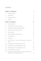
1 Introduction 7 1.1 Package Contents 7 1.2 Speciications 8 1.3 Motherboard Layout 12 1.4 I/O Panel 15 Chapter 2 Installation 17 2.1 31 2.8 Dr. Debug 32 2.9 SLITM , 3-Way SLITM , 4-Way SLITM and Quad SLITM Operation Guide 34 2.9.1 Installing Two SLITM-Ready Graphics Cards 34 - ASRock X99 Extreme11 | User Manual - Page 5
49 2.13 Dual LAN and Teaming Operation Guide 50 Chapter 3 Software and Utilities Operation 51 3.1 Installing Drivers 51 3.2 A-Tuning 52 3.3 ASRock APP Shop 58 3.3.1 UI Overview 58 3.3.2 Apps 59 3.3.3 BIOS & Drivers 62 3.3.4 Setting 63 3.4 Start8 64 Chapter 4 UEFI SETUP UTILITY - ASRock X99 Extreme11 | User Manual - Page 6
4.4.2 Chipset Coniguration 82 4.4.3 Storage Coniguration 84 4.4.4 Super IO Coniguration 85 4.4.5 ACPI Coniguration 86 4.4.6 USB Coniguration 87 4.5 Tools 88 4.6 Hardware Health Event Monitoring Screen 93 4.7 Security Screen 95 4.8 Boot Screen 96 4.9 Exit Screen 99 - ASRock X99 Extreme11 | User Manual - Page 7
http://www.asrock.com. 1.1 Package Contents • ASRock X99 Extreme11 Motherboard (EATX Form Factor) • ASRock X99 Extreme11 Quick Installation Guide • ASRock X99 Extreme11 Support CD • 1 x I/O Panel Shield • 2 x ASRock SLI_Bridge Cards • 1 x ASRock SLI_Bridge_3S Card • 1 x ASRock 3-Way SLI Bridge Card - ASRock X99 Extreme11 | User Manual - Page 8
• Supports Untied Overclocking Technology Chipset • Intel® X99 Memory • Quad Channel DDR4 Memory Technology • 8 x DDR4 DIMM Slots • Supports DDR4 3200+(OC)*/2933(OC)/2800(OC)/2400 (OC)/2133/1866/ 1600/1333/1066 non-ECC, un-bufered memory * Please refer to Memory Support List on ASRock's website - ASRock X99 Extreme11 | User Manual - Page 9
X99 Extreme11 Audio LAN Rear Panel I/O • 7.1 CH HD Audio with Content Protection (Realtek ALC1150 Audio Codec) • Premium Blu-ray Audio support • Supports Surge Protection (ASRock Full Spike Protection) • Supports Purity Sound™ 2 - Nichicon Fine Gold Series Audio Caps - 115dB SNR DAC with - ASRock X99 Extreme11 | User Manual - Page 10
Gb/s/SATA3 6.0 Gb/s Connectors by LSI SAS 3008 controller, support RAID (RAID 0, RAID 1, RAID 1E and RAID 10), NCQ, Hot Plug and ASRock HDD Saver Technology • 2 x eSATA Connectors, support NCQ, AHCI and Hot Plug • 2 x Ultra M.2 Sockets, support M.2 SATA3 6.0 Gb/s module and M.2 PCI Express module up - ASRock X99 Extreme11 | User Manual - Page 11
X99 Extreme11 BIOS Feature Hardware Monitor OS Certiications • 2 x 128Mb AMI UEFI Legal BIOS with multilingual GUI support (1 x Main BIOS and 1 x Backup BIOS) • Supports Secure Backup UEFI Technology • ACPI 1.1 Compliant wake up events • SMBIOS 2.3.1 Support • CPU, DRAM, PCH 1.05V, PCH 1.5V, VPPM - ASRock X99 Extreme11 | User Manual - Page 12
1.3 Motherboard Layout 12 3 45 11 CHA_FAN3 12 13 SATA3_0_3 14 Intel X99 15 SATA3_1_4 SAS_0_1 SATA3_2_5 X99 Extreme11 16 Purity SoundTM 2 PCIE3 LSI PLED1 1 CHA_FAN2 CHA_FAN1 BIOS_SEL1 A B BIOS_A 128Mb BIOS BIOS_B 128Mb BIOS PLED PWRBTN 1 HDLED RESET PANEL1 SAS_6_7 SB_FAN1 - ASRock X99 Extreme11 | User Manual - Page 13
Fan Connector (CPU_FAN2) 8 ATX Power Connector (ATXPWR1) 9 USB BIOS Selection Switch (BIOS_SEL1) 29 Chassis Fan Connector (CHA_FAN1) 30 Chassis Fan Connector (CHA_FAN2) 31 USB 2.0 Header (USB4_5) 32 USB 2.0 Header (USB6_7) 33 COM Port Header (COM1) 34 PCIe Power Connector (PCIE_PWR2) X99 Extreme11 - ASRock X99 Extreme11 | User Manual - Page 14
No. Description 35 Front Panel Audio Header (HD_AUDIO1) 36 Power Fan Connector (PWR_FAN1) 37 PCIe Power Connector (PCIE_PWR1) 38 Clear CMOS Jumper (CLRCMOS1) 14 English - ASRock X99 Extreme11 | User Manual - Page 15
1.4 I/O Panel 1 X99 Extreme11 57 2 3 4 68 16 15 14 13 12 11 10 9 No. Description 1 USB 2.0 Ports (USB01) 2 USB 2.0 Ports (USB23) 3 LAN RJ-45 Port (Intel® I211AT)* 4 LAN RJ- - ASRock X99 Extreme11 | User Manual - Page 16
the Rear Speaker, Central/Bass, and Front Speaker, or select "Realtek HDA Audio 2nd output" to use the front panel audio. *** he eSATA connector supports SATA with cables within 1 meters. he S_SATA3_3 connector is shared with the ESATA1 port; the S_SATA3_1 connector is shared with the ESATA2 port - ASRock X99 Extreme11 | User Manual - Page 17
X99 Extreme11 Chapter 2 Installation his is an EATX form factor motherboard. Before you install the motherboard, study the coniguration of your chassis to ensure that the motherboard its into it. Pre-installation Precautions Take note of the following precautions before you install motherboard - ASRock X99 Extreme11 | User Manual - Page 18
situation is found. Otherwise, the CPU will be seriously damaged. 2. Unplug all power cables before installing the CPU. CAUTION: Please note that X99 platform is only compatible with the LGA 2011-3 socket, which is incompatible with the LGA 2011 socket (for X79 platform). 1 A B A 2 B 18 English - ASRock X99 Extreme11 | User Manual - Page 19
X99 Extreme11 A 3 B 4 5 19 English - ASRock X99 Extreme11 | User Manual - Page 20
6 A B 7 A B 8 Please save and replace the cover if the processor is removed. he cover must be placed if you wish to return the motherboard for ater service. 20 English - ASRock X99 Extreme11 | User Manual - Page 21
2.2 Installing the CPU Fan and Heatsink X99 Extreme11 1 2 CPU_FAN 21 English - ASRock X99 Extreme11 | User Manual - Page 22
Installation of Memory Modules (DIMM) his motherboard provides eight 288-pin DDR4 (Double Data Rate 4) DIMM slots, and supports Quad Channel Memory Technology. 1. For quad Populated Populated Populated Populated • Due to Intel® CPU spec deinition, please install the memory modules on DDR4_A1, - ASRock X99 Extreme11 | User Manual - Page 23
X99 Extreme11 1 2 3 23 English - ASRock X99 Extreme11 | User Manual - Page 24
CrossFireXTM Mode x16 x16 N/A x16 N/A or 3-Way SLITM Mode Four Graphics Cards in 4-Way CrossFireXTM Mode x16 x16 N/A x16 x16 or 4-Way SLITM Mode For a better thermal environment, please connect a chassis fan to the motherboard's chassis fan connector (CHA_FAN1, CHA_FAN2 or CHA_FAN3 - ASRock X99 Extreme11 | User Manual - Page 25
X99 Extreme11 2.5 Jumpers Setup he illustration shows how jumpers are setup. When the jumper the CMOS when you just inish updating the BIOS, you must boot up the system irst, and then shut it down before you do the clear-CMOS action. Please be noted that the password, date, time, and user default - ASRock X99 Extreme11 | User Manual - Page 26
jumper caps over the headers and connectors will cause permanent damage to the motherboard. System Panel Header (9-pin PANEL1) (see p.12, No. 25) to the power switch on the chassis front panel. You may conigure the way to turn of your system using the power switch. RESET (Reset Switch): Connect - ASRock X99 Extreme11 | User Manual - Page 27
SAS_0_1 SATA3_5 SATA3_4 SATA3_3 S_SATA3_3 S_SATA3_1 X99 Extreme11 hese ten SATA3 connectors support SATA data cables for internal storage S_SATA3_0 will not function. * RAID is supported on SATA3_0 ~ SATA3_5 ports only. hese eight SAS-3 connectors support SAS/ SATA data cables for internal - ASRock X99 Extreme11 | User Manual - Page 28
I/O panel, there are two headers on this motherboard. Each USB 3.0 header can support two ports. Front Panel Audio Header (9-pin HD_AUDIO1 supports Jack Sensing, but the panel wire on the chassis must support HDA to function correctly. Please follow the instructions in our manual and chassis manual - ASRock X99 Extreme11 | User Manual - Page 29
X99 Extreme11 Chassis, Power and SB Fan Connectors (4-pin CHA_FAN1) (see p.12, No. 29) please connect it to Pin 1-3. ATX Power Connector (24-pin ATXPWR1) (see p.12, No. 8) 12 24 1 13 his motherboard provides a 24-pin ATX power connector. To use a 20-pin ATX power supply, please plug it along - ASRock X99 Extreme11 | User Manual - Page 30
) (4-pin PCIE_PWR2) (see p.12, No. 34) GND +12V DETECT his motherboard provides an 8-pin ATX 12V power connector. To use a 4-pin ATX power supply, please plug it along Pin 1 and Pin 5. Please connect a to manage the power state of HDD. his COM1 header supports a serial port module. English 30 - ASRock X99 Extreme11 | User Manual - Page 31
X99 Extreme11 2.7 Smart Switches he motherboard has four smart switches: Power Switch, Reset Switch, Clear CMOS Switch and one BIOS Selection Switch, allowing users to quickly turn on/of the system, reset the system, clear the CMOS values or boot from diferent BIOS. Power Switch (PWRBTN) (see p.12 - ASRock X99 Extreme11 | User Manual - Page 32
. Debug is used to provide code information, which makes troubleshooting even easier. Please see the diagrams below for reading the Dr. Debug codes. Code Description 00 Please check if the CPU is installed correctly and then clear CMOS. 0d Problem related to memory, VGA card or other devices - ASRock X99 Extreme11 | User Manual - Page 33
X99 Extreme11 b4 Problem related to USB devices. Please try removing all USB devices. b7 Problem related to memory. Please re-install the CPU and memory then clear CMOS. If the problem still exists, please install only one memory module or try using other memory modules. d6 he VGA could - ASRock X99 Extreme11 | User Manual - Page 34
2.9 SLITM , 3-Way SLITM , 4-Way SLITM and Quad SLITM Operation Guide his motherboard supports NVIDIA® SLITM , 3-Way SLITM, 4-Way SLITM and Quad SLITM (Scalable Link Interface) technology that allows you to install up to three identical PCI Express x16 graphics cards. Currently, NVIDIA® SLITM - ASRock X99 Extreme11 | User Manual - Page 35
X99 Extreme11 Step 3 Align and insert the ASRock SLI_ Bridge_3S Card to the goldingers on each graphics card. Make sure the ASRock SLI_ Bridge_3S Card is irmly in place. SLI_Bridge_3S Card ASRock SLI_Bridge_3S Card Step 4 Connect a VGA cable or a DVI cable to the monitor connector or the DVI - ASRock X99 Extreme11 | User Manual - Page 36
graphics card are connected. Repeat this step on the three graphics cards. Step 3 Align and insert the ASRock 3-Way SLI Bridge Card to the goldingers on each graphics card. Make sure the ASRock 3-Way SLI Bridge Card is irmly in place. ASRock 3-Way SLI Bridge Card 36 3-Way SLI Bridge English - ASRock X99 Extreme11 | User Manual - Page 37
X99 Extreme11 Step 4 Connect a VGA cable or a DVI cable to the monitor connector or the DVI connector of the graphics card that is inserted to PCIE1 slot. 37 English - ASRock X99 Extreme11 | User Manual - Page 38
. Repeat this step on the three graphics cards. SLI_Bridge_3S Card Step 3 Align and insert an ASRock SLI Bridge Card to the goldingers of the irst and second graphics card. Install the second ASRock SLI Bridge Card to the goldingers of the third and fourth graphics card. Connect the second and the - ASRock X99 Extreme11 | User Manual - Page 39
X99 Extreme11 Step 4 Connect a VGA cable or a DVI cable to the monitor connector or the DVI connector of the graphics card that is inserted to PCIE1 slot. 39 English - ASRock X99 Extreme11 | User Manual - Page 40
to enable the multi-GPU. Step 1 Double-click the NVIDIA Control Panel icon in the Windows® system tray. Step 2 In the let pane, click Set SLI and PhysX coniguration. hen select Maximize 3D performance and click Apply. Step 3 Reboot your system. 40 English - ASRock X99 Extreme11 | User Manual - Page 41
X99 Extreme11 2.10 CrossFireXTM, 3-Way CrossFireXTM, 4-Way CrossFireXTM and Quad CrossFireXTM Operation Guide his motherboard supports CrossFireXTM, 3-way CrossFireXTM, 4-way . Please refer to AMD graphics card manuals for detailed installation guide. 2.10.1 Installing Two CrossFireXTM-Ready Graphics - ASRock X99 Extreme11 | User Manual - Page 42
Step 3 Connect a VGA cable or a DVI cable to the monitor connector or the DVI connector of the graphics card that is inserted to PCIE1 slot. 42 English - ASRock X99 Extreme11 | User Manual - Page 43
X99 Extreme11 2.10.2 Installing Three CrossFireXTM-Ready Graphics Cards Step 1 Insert one PCIE4 slots. (he CrossFire Bridge is provided with the graphics card you purchase, not bundled with this motherboard. Please refer to your graphics card vendor for details.) Step 3 Connect a VGA cable or a DVI - ASRock X99 Extreme11 | User Manual - Page 44
the Radeon graphics cards on PCIE4 and PCIE5 slots. (he CrossFire Bridge is provided with the graphics card you purchase, not bundled with this motherboard. Please refer to your graphics card vendor for details.) Step 3 Connect a VGA cable or a DVI cable to the monitor connector or the DVI connector - ASRock X99 Extreme11 | User Manual - Page 45
X99 Extreme11 2.10.4 Driver Installation and Setup Step 1 Power on your computer and previously installed Catalyst drivers prior to installation. Please check AMD's website for AMD driver updates. Step 3 Install the required drivers and CATALYST Control Center then restart your computer. Please - ASRock X99 Extreme11 | User Manual - Page 46
2.11 M.2_SSD (NGFF) Module Installation Guide he M.2, also known as the Next Generation Form Factor (NGFF), is a small size and versatile card edge connector that aims to replace mPCIe and mSATA. - ASRock X99 Extreme11 | User Manual - Page 47
E D C B A E D NUT2 NUT1 X99 Extreme11 Step 3 Move the standof based on the module type and length. he standof is placed at the nut location D by default. Skip Step 3 and 4 and go straight to Step 5 if you are going to use the default nut. Otherwise, release the standof by hand. Step 4 Peel - ASRock X99 Extreme11 | User Manual - Page 48
M.2_SSD (NGFF) Module Support List PCIe Interface SATA Interface Plextor PX-G512M6e Plextor PX-G256M6e SanDisk SSDSCKGW080A401/80G Kingston RBU-SM2280S3/120G For the latest updates of M.2_SSD (NFGG) module support list, please visit our website for details: http://www.asrock.com English 48 - ASRock X99 Extreme11 | User Manual - Page 49
X99 Extreme11 2.12 HDD Saver Cable Installation Guide The HDD Saver Connector on this motherboard allows you to switch on SATA HDD(s). * he HDD Saver Connector supports up to two SATA HDDs. 2. Connect one end of the SATA data cable to a SATA port on the motherboard. hen connect the other end to your - ASRock X99 Extreme11 | User Manual - Page 50
2.13 Dual LAN and Teaming Operation Guide Dual LAN with Teaming enabled on this motherboard allows two single connections to act as . Before setting up Teaming, please make sure whether your Switch (or Router) supports Teaming (IEEE 802.3ad Link Aggregation). You can specify a preferred adapter in - ASRock X99 Extreme11 | User Manual - Page 51
X99 Extreme11 Chapter 3 Software and Utilities Operation 3.1 Installing Drivers he Support CD that comes with the motherboard contains necessary drivers and useful utilities that enhance the motherboard's features. Running The Support CD To begin using the support CD, insert the CD into your CD-ROM - ASRock X99 Extreme11 | User Manual - Page 52
RAM, Dehumidiier, Good Night LED, FAN-Tastic Tuning, OC Tweaker and a whole lot more. 3.2.1 Installing A-Tuning When you install the all-in-one driver to your system from ASRock's support Tweaker, System Info, Live Update, Tech Service and Settings. Operation Mode Choose an operation mode for your - ASRock X99 Extreme11 | User Manual - Page 53
X99 Extreme11 XFast RAM Boost the system's performance and extend the HDD's or SDD's lifespan! Create a hidden partition, then assign which iles should be stored in the RAM note that Ultra Fast mode is only supported by Windows 8.1/8 and the VBIOS must support UEFI GOP if you are using an external - ASRock X99 Extreme11 | User Manual - Page 54
assigned temperature is met. Dehumidiier Prevent motherboard damages due to dampness. Enable this proile to the friends. HDD Saver A quick-and-easy way to power up and down the drive on demand. Use . HDD, SSD and optical disk drives are all supported. he health status block displays Good (in green - ASRock X99 Extreme11 | User Manual - Page 55
OC Tweaker Conigurations for overclocking the system. X99 Extreme11 System Info View information about the system. *he System Browser tab may not appear for certain models. 55 English - ASRock X99 Extreme11 | User Manual - Page 56
Live Update Check for newer versions of BIOS or drivers. Tech Service Contact Tech Service if you have problems with your computer. Please leave your contact information along with details of the problem. 56 English - ASRock X99 Extreme11 | User Manual - Page 57
X99 Extreme11 Settings Conigure ASRock A-Tuning. Click to select "Auto run at Windows Startup" if you want A-Tuning to be launched when you start up the Windows operating system. 57 English - ASRock X99 Extreme11 | User Manual - Page 58
is an online store for purchasing and downloading sotware applications for your ASRock computer. You can install various apps and support utilities quickly and easily, and optimize your system and keep your motherboard up to date simply with a few clicks. Double-click on your desktop to access - ASRock X99 Extreme11 | User Manual - Page 59
X99 Extreme11 3.3.2 Apps When the "Apps" tab is selected, you will see all the available apps on up and down to see more apps listed. You can check the price of the app and whether you have already intalled it or not. - he red icon displays the price or "Free" if the app is free of charge. - he - ASRock X99 Extreme11 | User Manual - Page 60
Step 3 If you want to install the app, click on the red icon to start downloading. Step 4 When installation completes, you can ind the green "Installed" icon appears on the upper right corner. English To uninstall it, simply click on the trash can icon . *he trash icon may not appear for certain - ASRock X99 Extreme11 | User Manual - Page 61
X99 Extreme11 Upgrading an App You can only upgrade the apps you have already installed. When there is an available new version for your app, you will - ASRock X99 Extreme11 | User Manual - Page 62
recommended or critical updates for the BIOS or drivers. Please update them all soon. Step 1 Please check the item information before update. Click on Step 2 to see more details. Click to select one or more items you want to update. Step 3 Click Update to start the update process. 62 English - ASRock X99 Extreme11 | User Manual - Page 63
X99 Extreme11 3.3.4 Setting In the "Setting" page, you can change the language, select the server location, and determine if you want to automatically run the ASRock APP Shop on Windows startup. 63 English - ASRock X99 Extreme11 | User Manual - Page 64
customizations for greater eiciency. 3.4.1 Installing Start8 Install Start8, which is located in the folder at the following path of the Support CD: \ ASRock Utility > Start8. 3.4.2 Coniguring Start8 Style Select between the Windows 7 style and Windows 8 style Start Menu. hen select the theme of - ASRock X99 Extreme11 | User Manual - Page 65
Conigure X99 Extreme11 Conigure provides coniguration options, including icon sizes, which shortcuts you want Start Menu to display, quick access to recently used apps, the functionality of the power button, and more. Control 65 English - ASRock X99 Extreme11 | User Manual - Page 66
Control lets you conigure what a click on the start button or a press on the Windows key does. Desktop Desktop allows you to disable the hot corners when you are working on the desktop. It also lets you choose whether or not the system boots directly into desktop mode and bypass the Metro user - ASRock X99 Extreme11 | User Manual - Page 67
X99 Extreme11 Chapter and then back on. Because the UEFI sotware is constantly being updated, the following UEFI setup screens and descriptions are for reference purpose only Main For setting system time/date information OC Tweaker For overclocking conigurations Advanced For advanced system - ASRock X99 Extreme11 | User Manual - Page 68
4.1.2 Navigation Keys Use < > key or < > key to choose among the selections on the menu bar, and use < > key or < > key to move the cursor up or down to select items, then press to get into the sub screen. You can also use the mouse to click your required item. Please check the following - ASRock X99 Extreme11 | User Manual - Page 69
X99 Extreme11 4.2 Main Screen When you enter the UEFI SETUP UTILITY, the Main screen will appear and display the system overview. Favorite Display your collection of BIOS items. Press F5 to add/remove your favorite items. 69 English - ASRock X99 Extreme11 | User Manual - Page 70
Tweaker screen, you can set up overclocking features. Because the UEFI sotware is constantly being updated, the following UEFI setup screens and this option to load optimized CPU overclocking setting. Please note that overclocking may cause damage to your CPU and motherboard. It should be done at - ASRock X99 Extreme11 | User Manual - Page 71
X99 Extreme11 CPU Cache Ratio he CPU Internal Bus Speed Ratio. he maximum should be the highest performance state. Filter PLL Frequency CPU BCLK Filter Frequency. Choose 1.6 for better overclocking capabilities. Long Duration Power Limit Conigure Package Power Limit 1 in watts. When the limit is - ASRock X99 Extreme11 | User Manual - Page 72
Voltage. he default value is [Auto]. DRAM Reference Clock Select Auto for optimized settings. DRAM Frequency If [Auto] is selected, the motherboard will detect the memory module(s) inserted and assign the appropriate frequency automatically. DRAM Frequency OC Preset If the DRAM frequency is selected - ASRock X99 Extreme11 | User Manual - Page 73
X99 Extreme11 Primary Timing CAS# Latency (tCL) he time between sending a column address to the memory and the beginning of the data in response. RAS# to CAS# - ASRock X99 Extreme11 | User Manual - Page 74
Write to Read Delay (tWTR) he number of clocks between the last valid write operation and the next read command to the same internal bank. Write to Read Delay (tWTR_L) he number of clocks between the last valid write operation and the next read command to the same internal bank. Read to Precharge ( - ASRock X99 Extreme11 | User Manual - Page 75
X99 Extreme11 tRWSR Conigure READ to WRITE same rank dead cycle Back to back READ to WRITE from same rank separation parameter. tRWDD Conigure Read to Write - ASRock X99 Extreme11 | User Manual - Page 76
A. ODT PARK (CH A) Conigure the memory on die termination resistors' PARK for channel A. ODT NOM (CH A) Use this to change ODT (CH A) Auto/Manual settings. he default is [Auto]. ODT WR (CH B) Conigure the memory on die termination resistors' WR for channel B. ODT PARK (CH B) Conigure the memory - ASRock X99 Extreme11 | User Manual - Page 77
X99 Extreme11 Memory Test Enable/disable memory test during normal boot. Memory Test On Conigure the voltage for the CPU Cache. Setting the voltage higher may increase system stability when overclocking. System Agent Voltage Ofset Conigure the voltage for the System Agent. Setting the voltage higher - ASRock X99 Extreme11 | User Manual - Page 78
CPU Integrated VR Eiciency Mode Enable FIVR Eiciency Management for power saving. Disable for better performance and overclocking capabilities. Voltage Coniguration Power Saving Mode Enable Power Saving Mode to reduce power consumption. CPU Input Voltage Conigure the voltage for the CPU. CPU Load- - ASRock X99 Extreme11 | User Manual - Page 79
X99 Extreme11 4.4 Advanced Screen In this section, you may set the conigurations for Auto] is selected, the resolution will be set to 1920 x 1080 if the monitor supports Full HD resolution. If the monitor does not support Full HD resolution, then the resolution will be set to 1024 x 768. When [ - ASRock X99 Extreme11 | User Manual - Page 80
4.4.1 CPU Coniguration Intel Hyper Threading Technology Intel Hyper hreading Technology allows multiple threads to run on each core, so that the overall performance on threaded sotware is improved. Active Processor Cores Select the number of cores to enable in each processor package. No-Execute - ASRock X99 Extreme11 | User Manual - Page 81
X99 Extreme11 CPU Thermal Throttling Enable CPU internal thermal control mechanisms to keep the CPU from overheating. CPU C States Support Enable CPU C States Support for power saving. It is recommended to keep C3, C6 and C7 all enabled for better power saving. Package C State Support Enable CPU, - ASRock X99 Extreme11 | User Manual - Page 82
4G Decoding Enable/disable the 64-bit capable devices to be decoded in above 4G address space. *he function is only applied to system that supports 64-bit PCI decoding. PCIE1.2.3.4 and 5 Link Speed Select the link speed for PCIE1, PCIE2, PCIE3, PCIE4 and PCIE5. PCI-E ASPM - ASRock X99 Extreme11 | User Manual - Page 83
X99 Extreme11 PCH DMI ASPM Support his option enables/disables the ASPM support for all PCH DMI devices. Inte(R) Ethernet Connection I218-V Enable or disable the onboard network interface controller (Intel® I218V). Inte(R) Ethernet Connection I211 Enable or - ASRock X99 Extreme11 | User Manual - Page 84
4.4.3 Storage Coniguration Hard Disk S.M.A.R.T. S.M.A.R.T stands for Self-Monitoring, Analysis, and Reporting Technology. It is a monitoring system for computer hard disk drives to detect and report on various indicators of reliability. 84 English - ASRock X99 Extreme11 | User Manual - Page 85
4.4.4 Super IO Coniguration X99 Extreme11 Serial Port Enable or disable the Serial port. Serial Port Address Select the address of the Serial port. PS2 Y-Cable Enable the PS2 Y-Cable or set this option to Auto. 85 English - ASRock X99 Extreme11 | User Manual - Page 86
4.4.5 ACPI Coniguration Suspend to RAM Select disable for ACPI suspend type S1. It is recommended to select auto for ACPI S3 power saving. PS/2 Keyboard Power On Allow the system - ASRock X99 Extreme11 | User Manual - Page 87
4.4.6 USB Coniguration X99 Extreme11 USB Controller Enable or disable all the USB ports. Intel USB 3.0 Mode Select Intel® USB 3.0 controller mode. Set [Smart Auto] to keep the USB 3.0 driver enabled ater rebooting (USB 3.0 is enabled in BIOS). Set [Auto] to automatically enable the USB 3.0 driver - ASRock X99 Extreme11 | User Manual - Page 88
4.5 Tools System Browser ASRock System Browser shows the overview of your current PC and the devices connected. OMG (Online Management Guard) Administrators are able to establish an internet curfew - ASRock X99 Extreme11 | User Manual - Page 89
X99 Extreme11 Dehumidiier CPU Fan Setting Conigure the speed of the CPU fan while Dehumidiier . Set [Disabled] to switch of the HDD Saver. It is recommended to enable the AHCI Mode to fully support the HDD Saver. You can also enable/disable the HDD Saver via the HDD Saver application under your OS. - ASRock X99 Extreme11 | User Manual - Page 90
from our support CD, Easy Driver Installer is a handy tool in the UEFI that installs the LAN driver to your system via an USB storage device, then downloads and installs the other required drivers automatically. UEFI Tech Service Contact ASRock Tech Service if you are having trouble with your - ASRock X99 Extreme11 | User Manual - Page 91
X99 Extreme11 Boot Manager Timeout Enable/disable the Boot Manager Timeout. Timeout Seconds Conigure the number of seconds to wait for the Boot Manager. Instant Flash Save UEFI iles in your USB storage device and run Instant Flash to update your UEFI. Internet Flash - DHCP (Auto IP), Auto ASRock - ASRock X99 Extreme11 | User Manual - Page 92
Internet Setting Enable or disable sound efects in the setup utility. UEFI Download Server Select a server to download the UEFI irmware. Save User Default Type a proile name and press enter to save your settings as user default. Load User Default Load previously saved user defaults. 92 English - ASRock X99 Extreme11 | User Manual - Page 93
X99 Extreme11 4.6 Hardware Health Event Monitoring Screen his section allows you to monitor the status of the hardware on your system, including the parameters of the CPU temperature, motherboard temperature, fan speed and voltage. FAN-Tastic Tuning Conigure up to ive diferent fan speeds using the - ASRock X99 Extreme11 | User Manual - Page 94
temperatures and assign a respective fan speed for each temperature. Over Temperature Protection When Over Temperature Protection is enabled, the system automatically shuts down when the motherboard is overheated. 94 English - ASRock X99 Extreme11 | User Manual - Page 95
X99 Extreme11 4.7 Security Screen In this section you may set or change the supervisor/user password for the system. You may also clear Utility. Leave it blank and press enter to remove the password. Secure Boot Use this item to enable or disable support for Windows 8.1/8 Secure Boot. 95 English - ASRock X99 Extreme11 | User Manual - Page 96
Windows 8.1/8 and the VBIOS must support UEFI GOP if you are using an external graphics card. Please notice that Ultra Fast mode will boot so fast that the only way to enter this UEFI Setup Utility is to Clear CMOS or run the Restart to UEFI utility in Windows. Boot From Onboard - ASRock X99 Extreme11 | User Manual - Page 97
X99 Extreme11 Full Screen Logo Enable to display the boot logo or disable to show normal POST messages. AddOn ROM Display Enable AddOn ROM Display to see - ASRock X99 Extreme11 | User Manual - Page 98
Launch Storage OpROM Policy Select UEFI only to run those that support UEFI option ROM only. Select Legacy only to run those that support legacy option ROM only. Do not launch? Launch Video OpROM Policy Select UEFI only to run those that support UEFI option ROM only. Select Legacy only to run those - ASRock X99 Extreme11 | User Manual - Page 99
4.9 Exit Screen X99 Extreme11 Save Changes and Exit When you select this option the following message, "Save coniguration changes and exit setup?" will pop out. Select [OK] to save - ASRock X99 Extreme11 | User Manual - Page 100
or want to know more about ASRock, you're welcome to visit ASRock's website at http://www.asrock.com; or you may contact your dealer for further information. For technical questions, please submit a support request form at http://www.asrock.com/support/tsd.asp ASRock Incorporation 2F., No.37, Sec
-
 1
1 -
 2
2 -
 3
3 -
 4
4 -
 5
5 -
 6
6 -
 7
7 -
8
-
9
-
10
-
11
-
12
-
13
-
14
-
15
-
16
-
17
-
18
-
19
-
20
-
21
-
22
-
23
-
24
-
25
-
26
-
27
-
28
-
29
-
30
-
31
-
32
-
33
-
34
-
35
-
36
-
37
-
38
-
39
-
40
-
41
-
42
-
43
-
44
-
45
-
46
-
47
-
48
-
49
-
50
-
51
-
52
-
53
-
54
-
55
-
56
-
57
-
58
-
59
-
60
-
61
-
62
-
63
-
64
-
65
-
66
-
67
-
68
-
69
-
70
-
71
-
72
-
73
-
74
-
75
-
76
-
77
-
78
-
79
-
80
-
81
-
82
-
83
-
84
-
85
-
86
-
87
-
88
-
89
-
90
-
91
-
92
-
93
-
94
-
95
-
96
-
97
-
98
-
99
-
100
 |
 |
X99 Extreme11
X99 Extreme11