ASRock X99 Extreme4/3.1 Quick Installation Guide
ASRock X99 Extreme4/3.1 Manual
 |
View all ASRock X99 Extreme4/3.1 manuals
Add to My Manuals
Save this manual to your list of manuals |
ASRock X99 Extreme4/3.1 manual content summary:
- ASRock X99 Extreme4/3.1 | Quick Installation Guide - Page 1
change without notice, and should not be constructed as a commitment by ASRock. ASRock assumes no responsibility for any errors or omissions that may appear in CALIFORNIA, USA ONLY he Lithium battery adopted on this motherboard contains Perchlorate, a toxic substance controlled in Perchlorate Best - ASRock X99 Extreme4/3.1 | Quick Installation Guide - Page 2
Manufactured under license under U.S. Patent Nos: 5,956,674; 5,974,380; 6,487,535; 7,003,467 & other U.S. and worldwide patents issued & pending. DTS, the Symbol, & DTS and the Symbol together is a registered trademark & DTS Connect, DTS Interactive, DTS Neo:PC are trademarks of DTS, Inc. Product - ASRock X99 Extreme4/3.1 | Quick Installation Guide - Page 3
Motherboard Layout 12 PS2 Mouse PS2 Keyboard CLRC BTN1 USB 2.0 T: USB0 B: USB1 USB 2.0 T: USB2 B: USB3 ESATA1 USB 3.0 T: USB0 B: USB1 USB 3.0 T: USB2 B: USB3 Top: RJ-45 X99 Extreme4/3.1 3 4 56 7 ATX12V1 CPU_FAN1 CPU_FAN2 2011-3 Socket 8 DDR4_D2 (64 bit, 288-pin module) DDR4_D1 (64 bit, - ASRock X99 Extreme4/3.1 | Quick Installation Guide - Page 4
2 x 288-pin DDR4 DIMM Slots (DDR4_D1, DDR4_C1) 8 ATX Power Connector (ATXPWR1) 9 USB 3.0 Header (USB3_4_5) 10 Chassis Fan Connector (CHA_FAN3) 11 PANEL1) 22 HDD Saver Connector (SATA_PWR_1) 23 USB 2.0 Header (USB4_5) 24 USB 2.0 Header (USB6_7) 25 BIOS Selection Jumper (BIOS_SEL1) 26 Clear CMOS Jumper - ASRock X99 Extreme4/3.1 | Quick Installation Guide - Page 5
I/O Panel 1 X99 Extreme4/3.1 46 2 3 57 15 14 13 No. Description 1 PS/2 Mouse Port 2 USB 2.0 Ports (USB23) 3 LAN RJ-45 Port* 4 Central / Bass (Orange) 5 Rear Speaker (Black) 6 Line In (Light Blue) 7 Front Speaker (Lime)** 8 Microphone (Pink) 12 11 10 98 - ASRock X99 Extreme4/3.1 | Quick Installation Guide - Page 6
use the Rear Speaker, Central/Bass, and Front Speaker, or select "Realtek HDA Audio 2nd output" to use the front panel audio. *** he eSATA connector supports SATA with cables within 1 meters. he S_SATA3_3 connector is shared with the eSATA port English 4 - ASRock X99 Extreme4/3.1 | Quick Installation Guide - Page 7
website as well. ASRock website http://www.asrock.com. 1.1 Package Contents • ASRock X99 Extreme4/3.1 Motherboard (ATX Form Factor) • ASRock X99 Extreme4/3.1 Quick Installation Guide • ASRock X99 Extreme4/3.1 Support CD • 1 x I/O Panel Shield • 1 x ASRock USB 3.1/A+C • 1 x ASRock SLI_Bridge_2S Card - ASRock X99 Extreme4/3.1 | Quick Installation Guide - Page 8
Untied Overclocking Technology Chipset • Intel® X99 Memory • Quad Channel DDR4 Memory Technology • 8 x DDR4 DIMM Slots • Supports DDR4 3200+(OC)*/2933(OC)/2800(OC)/2400 (OC)/2133 non-ECC, un-bufered memory * Please refer to Memory Support List on ASRock's website for more information. (http - ASRock X99 Extreme4/3.1 | Quick Installation Guide - Page 9
X99 Extreme4/3.1 * If you install CPU with 28 lanes, 3-Way SLITM is not supported. To support 3-Way SLITM, x Optical SPDIF Out Port • 4 x USB 2.0 Ports (Supports ESD Protection (ASRock Full Spike Protection)) • 4 x USB 3.0 Ports (Supports ESD Protection (ASRock Full Spike Protection)) • 1 x RJ - ASRock X99 Extreme4/3.1 | Quick Installation Guide - Page 10
Headers (support 4 USB 2.0 ports) (Supports ESD Protection (ASRock Full Spike Protection)) • 1 x USB 3.0 Header (Supports 2 USB 3.0 ports) (Supports ESD Protection (ASRock Full Spike Protection)) English BIOS Feature • 2 x 128Mb AMI UEFI Legal BIOS with multilingual GUI support (1 x Main BIOS and - ASRock X99 Extreme4/3.1 | Quick Installation Guide - Page 11
X99 Extreme4/3.1 Hardware Monitor OS Certiications • ACPI 1.1 Compliant wake up events • SMBIOS 2.3.1 Support visit our website: http://www.asrock.com Please realize that there is a certain risk involved with overclocking adjusting the setting in the BIOS, applying Untied Overclocking Technology, - ASRock X99 Extreme4/3.1 | Quick Installation Guide - Page 12
2 Installation his is an ATX form factor motherboard. Before you install the motherboard, study the coniguration of your chassis to ensure that the motherboard its into it. Pre-installation Precautions Take note of the following precautions before you install motherboard components or change any - ASRock X99 Extreme4/3.1 | Quick Installation Guide - Page 13
X99 Extreme4/3.1 2.1 Installing the CPU 1. Before you insert the 2011-3-Pin CPU will be seriously damaged. 2. Unplug all power cables before installing the CPU. CAUTION: Please note that X99 platform is only compatible with the LGA 2011-3 socket, which is incompatible with the LGA 2011 socket (for - ASRock X99 Extreme4/3.1 | Quick Installation Guide - Page 14
A 3 B 4 5 12 English - ASRock X99 Extreme4/3.1 | Quick Installation Guide - Page 15
X99 Extreme4/3.1 6 A B 7 A B 8 Please save and replace the cover if the processor is removed. he cover must be placed if you wish to return the motherboard for ater service. 13 English - ASRock X99 Extreme4/3.1 | Quick Installation Guide - Page 16
2.2 Installing the CPU Fan and Heatsink 1 14 2 CPU_FAN English - ASRock X99 Extreme4/3.1 | Quick Installation Guide - Page 17
X99 Extreme4/3.1 2.3 Installation of Memory Modules (DIMM) his motherboard provides eight 288-pin DDR4 (Double Data Rate 4) DIMM slots, and supports Quad Channel Memory Technology. 1. For quad channel coniguration, you always need to install identical (the same brand, speed, size and chip-type) - ASRock X99 Extreme4/3.1 | Quick Installation Guide - Page 18
1 2 3 16 English - ASRock X99 Extreme4/3.1 | Quick Installation Guide - Page 19
X99 Extreme4/3.1 2.4 Expansion Slots (PCI Express Slots) here are 5 PCI Express slots on the motherboard. Before installing an expansion card, please make sure that the power supply is switched of or the power cord is unplugged. Please read the documentation - ASRock X99 Extreme4/3.1 | Quick Installation Guide - Page 20
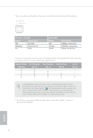
in 3-Way CrossFireXTM Mode x16 N/A x8 N/A x4 *3-Way SLITM Mode is not supported for CPU with 28 PCIe lanes. For a better thermal environment, please connect a chassis fan to the motherboard's chassis fan connector (CHA_FAN1, CHA_FAN2 or CHA_FAN3) when using multiple graphics cards. English - ASRock X99 Extreme4/3.1 | Quick Installation Guide - Page 21
X99 Extreme4/3.1 2.5 Jumpers Setup he illustration shows how jumpers are setup. When the jumper 5 seconds. However, please do not clear the CMOS right ater you update the BIOS. If you need to clear the CMOS when you just inish updating the BIOS, you must boot up the system irst, and then shut it down - ASRock X99 Extreme4/3.1 | Quick Installation Guide - Page 22
pin1 and pin2 again, then use "Secure Backup UEFI" in BIOS setup utility to copy the BIOS ile to the main BIOS to ensure normal system operation. For the sake of system safety, users cannot update the backup BIOS manually. Users may refer to the BIOS LED (BIOS_A_LED or BIOS_B_LED) to identify which - ASRock X99 Extreme4/3.1 | Quick Installation Guide - Page 23
X99 Extreme4/3.1 2.6 Onboard Headers and Connectors Onboard headers and connectors are NOT jumpers. Do NOT place jumper caps over these headers and connectors. Placing jumper caps over the headers and connectors will cause permanent damage to the motherboard. System Panel Header (9-pin PANEL1) (see - ASRock X99 Extreme4/3.1 | Quick Installation Guide - Page 24
PLEDPLED+ PLED+ SATA3_3 S_SATA3_3 S_SATA3_1 Please connect the chassis power LED to this header to indicate the system's power status. hese ten SATA3 connectors support SATA data cables for internal storage devices with up to 6.0 Gb/s data transfer rate. If the eSATA port on the rear I/O has been - ASRock X99 Extreme4/3.1 | Quick Installation Guide - Page 25
X99 Extreme4/3.1 USB 2.0 Headers (9-pin USB4_5) (see p.1, No. 23) (9-pin USB6_7) (see p.1, No. 24) USB_PWR PP+ GND DUMMY 1 GND P+ PUSB_PWR Besides four USB 2.0 ports on the I/O panel, there are two headers on this motherboard. Each USB 2.0 header can support two ports. USB 3.0 Header (19-pin - ASRock X99 Extreme4/3.1 | Quick Installation Guide - Page 26
pin ATX12V1) (see p.1, No. 3) 1 13 8 5 4 1 his motherboard provides a 24-pin ATX power connector. To use a 20-pin ATX power supply, please plug it along Pin 1 and Pin 13. his motherboard provides an 8-pin ATX 12V power connector. To use a 4-pin ATX power supply, please plug it along Pin 1 and - ASRock X99 Extreme4/3.1 | Quick Installation Guide - Page 27
X99 Extreme4/3.1 PCIe Power Connector (4-pin PCIE_PWR1) (see p.1, No. 31) Please ) (see p.1, No. 27) RRXD1 DDTR#1 DDSR#1 CCTS#1 1 RRI#1 RRTS#1 GND TTXD1 DDCD#1 his COM1 header supports a serial port module. TPM Header (17-pin TPMS1) (see p.1, No. 28) 1 GN D SMB_CLK_MAIN SMB_DATA_MAIN LAD2 - ASRock X99 Extreme4/3.1 | Quick Installation Guide - Page 28
2.7 Smart Switches he motherboard has a Clear CMOS Switch, allowing users to clear the CMOS values. Clear CMOS Switch (CLRCBTN) (see p.3, No. 14) Clear CMOS Switch allows users to quickly - ASRock X99 Extreme4/3.1 | Quick Installation Guide - Page 29
X99 Extreme4/3.1 2.8 M.2_SSD (NGFF) Module Installation Guide he M.2, also known as the Next Generation Form Factor (NGFF), is a small size and versatile card edge connector that aims to replace mPCIe and mSATA. - ASRock X99 Extreme4/3.1 | Quick Installation Guide - Page 30
hand. Step 4 Peel of the yellow protective ilm on the nut to be used. Hand tighten the standof into the desired nut location on the motherboard. Step 5 Align and gently insert the M.2 (NGFF) SSD module into the M.2 slot. Please be aware that the M.2 (NGFF) SSD module only its in one orientation - ASRock X99 Extreme4/3.1 | Quick Installation Guide - Page 31
X99 Extreme4/3.1 M.2_SSD (NGFF) Module Support List PCIe Interface SATA Interface Plextor PX-G512M6e Plextor PX-G256M6e SanDisk /80G Kingston RBU-SM2280S3/120G For the latest updates of M.2_SSD (NFGG) module support list, please visit our website for details: http://www.asrock.com English 29 - ASRock X99 Extreme4/3.1 | Quick Installation Guide - Page 32
2.9 HDD Saver Cable Installation Guide The HDD Saver Connector on this motherboard allows you to switch on and off your SATA HDD(s). * he HDD Saver Connector supports up to two SATA HDDs. 2. Connect one end of the SATA data cable to a SATA port on the motherboard. hen connect the other end to your - ASRock X99 Extreme4/3.1 | Quick Installation Guide - Page 33
X99 Extreme4/3.1 2.10 ASRock USB 3.1/A+C Installation Guide Speciications Platform • Size: 3.1-in x 3.2-in, 7.9 cm x 8.1 cm Controller • ASMedia ASM1142 Controller PCIE • PCI Express x4 Connector (x2 lane) • Compliant with PCI Express 1.1, 2.0 and 3.0 speciications • Supports data rates up to - ASRock X99 Extreme4/3.1 | Quick Installation Guide - Page 34
ASRock USB 3.1/A+C provides two external USB 3.1 ports which support transfer rates up to 10 Gbps. Follow the simple steps below to install the ASRock USB PCI Express slot on your motherboard and remove its slot bracket. *To maximize the performance of ASRock USB 3.1/A+C, it is highly recommended - ASRock X99 Extreme4/3.1 | Quick Installation Guide - Page 35
auf der ASRock-Webseite: ASRock-Website http://www.asrock.com. 1.1 Lieferumfang • ASRock X99 Extreme4/3.1 - Motherboard (ATX-Formfaktor) • ASRock X99 Extreme4/3.1 - Schnellinstallationsanleitung • ASRock X99 Extreme4/3.1 - Support-CD • 1 x E/A-Blendenabschirmung • 1 x ASRock-USB 3.1/A+C • 1 x ASRock - ASRock X99 Extreme4/3.1 | Quick Installation Guide - Page 36
Technische Daten Plattform • ATX-Formfaktor • Platine mit • Unterstützt Untied-Übertaktungstechnologie Chipsatz • Intel® X99 Speicher • Vierkanal-DDR4-Speichertechnologie • 8 x in der Speicherkompa- tibilitätsliste auf der ASRock-Webseite. (http://www.asrock. com/) • Unterstützt ECC-lose RDIMM - ASRock X99 Extreme4/3.1 | Quick Installation Guide - Page 37
X99 Extreme4/3.1 Audio LAN Rückblende, E/A • 15-μ-Goldkontakt in VGA-PCIe-Steckplatz (PCIE1 und PCIE3) • 7.1-Kanal-HD-Audio mit Inhaltsschutz (Realtek ALC1150Audiocodec) • Erstklassige Blu-ray-Audiounterstützung • Unterstützt Überspannungsschutz (ASRock Full Spike Protection) • Unterstützt Purity - ASRock X99 Extreme4/3.1 | Quick Installation Guide - Page 38
ASRock Full Spike Protection) • 1 x USB 3.1-Typ-C-Port (10 Gb/s)(unterstützt Schutz vor elektrostatischer Entladung (ASRock Full Spike Protection) • 10 x SATA-III-6,0-Gb/s-Anschlüsse per Intel® X99 üteranschluss (3-polig) • 1 x 24-poliger ATX-Netzanschluss • 1 x 8-poliger 12-V-Netzanschluss ( - ASRock X99 Extreme4/3.1 | Quick Installation Guide - Page 39
X99 Extreme4/3.1 BIOSFunktion Hardwareüberwachung Betriebssystem Zertiizierungen • 2 x 128-Mb-AMI-UEFI-Legal-BIOS mit Unterstützung mehrsprachiger graischer Benutzerschnittstellen (1 x Haupt-BIOS und 1 x Ausfall-BIOS haben keine derartigen Beschränkungen. Mit ASRock XFast RAM können Sie den Speicher - ASRock X99 Extreme4/3.1 | Quick Installation Guide - Page 40
3 an CLRCMOS1 5 Sekunden lang mit einer Jumper-Kappe kurz. Löschen Sie den CMOS jedoch nicht direkt nach der BIOS-Aktualisierung. Falls Sie den CMOS direkt nach Abschluss der BIOS-Aktualisierung löschen müssen, starten Sie das System zunächst; fahren Sie es dann vor der CMOS-Löschung herunter. Bitte - ASRock X99 Extreme4/3.1 | Quick Installation Guide - Page 41
X99 Extreme4/3.1 BIOS-Auswahl-Jumper (BIOS_SEL1) (siehe S. 1, Nr. 25) Standard Ausfall-BIOS (Haupt-BIOS) Dieses Motherboard verfügt über zwei integrierte BIOS, ein Haupt-BIOS (BIOS_ A) und ein Ausfall-BIOS (BIOS_B), die den Schutz in puncto Sicherheit und Stabilität Ihres Systems steigern. - ASRock X99 Extreme4/3.1 | Quick Installation Guide - Page 42
an diesen Stitleisten und Anschlüssen an. Durch Anbringen von Jumper-Kappen an diesen Stitleisten und Anschlüssen können Sie das Motherboard dauerhat beschädigen. Systemblende-Stitleiste (9-polig, PANEL1) (siehe S. 1, Nr. 21) PLED+ PLEDPWRBTN# GND 1 GND RESET# GND HDLEDHDLED+ Verbinden Sie - ASRock X99 Extreme4/3.1 | Quick Installation Guide - Page 43
S. 1, Nr. 15) SATA3_0 S_SATA3_2 S_SATA3_0 SATA3_3 S_SATA3_3 S_SATA3_1 X99 Extreme4/3.1 Diese zehn SATA-IIIAnschlüsse unterstützen SATA-Datenkabel für interne PUSB_PWR Neben vier USB 2.0-Ports an der E/A-Blende beinden sich zwei Stitleisten an diesem Motherboard. Jede USB 2.0-Stitleiste kann zwei - ASRock X99 Extreme4/3.1 | Quick Installation Guide - Page 44
+ Vbus IntA_PB_SSRXIntA_PB_SSRX+ GND IntA_PB_SSTXIntA_PB_SSTX+ GND IntA_PB_DIntA_PB_D+ Dummy 1 Neben vier USB 3.0-Ports an der E/A-Blende beindet sich eine Stitleiste an diesem Motherboard. Jede USB 3.0-Stitleiste kann zwei Ports unterstützen. Audiostitleiste (Frontblende) (9-polig - ASRock X99 Extreme4/3.1 | Quick Installation Guide - Page 45
X99 Extreme4/3.1 (3-polig, CHA_FAN3) (siehe S. 1, Nr. 10) (3-polig, PWR_FAN1) (siehe S. 1, Nr. 32) GND FAN_VOLTAGE CHA_FAN_SPEED CPU-Lüteranschlüsse (4-polig, CPU_FAN1) (siehe S. 1, Nr. 4) (3-polig, CPU_FAN2) (siehe S. 1, Nr. 6) ATX-Netzanschluss (24-polig, ATXPWR1) (siehe S. 1, Nr. 8) 4 3 21 - ASRock X99 Extreme4/3.1 | Quick Installation Guide - Page 46
HDD-Saver-Anschluss (4-polig, SATA_PWR_1) (siehe S. 1, Nr. 22) Bitte verbinden Sie zum 1 Verwalten des Energiestatus der Festplatte das HDD-Saver-Kabel mit diesem Anschluss. hunderboltErweiterungskartenanschluss (5-polig, TBT1) (siehe S. 1, Nr. 30) Serieller-Port-Stitleiste (9-polig, COM1) ( - ASRock X99 Extreme4/3.1 | Quick Installation Guide - Page 47
X99 Extreme4/3.1 1.5 Intelligente Schalter Das Motherboard verfügt über eine CMOS-Löschtaste zum Löschen der CMOSWerte. CMOS-löschen-Schalter (CLRCBTN) (siehe S. 3, Nr. 14) Mit dem CMOS-löschenSchalter können Benutzer die CMOS- - ASRock X99 Extreme4/3.1 | Quick Installation Guide - Page 48
Contenu de l'emballage • Carte mère ASRock X99 Extreme4/3.1 (facteur de forme ATX) • Guide d'installation rapide ASRock X99 Extreme4/3.1 • CD d'assistance ASRock X99 Extreme4/3.1 • 1 x panneau de protection E/S • 1 x USB 3.1 ASRock/A+C • 1 x carte ASRock SLI_Bridge_2S • Un carte pont à trois voies - ASRock X99 Extreme4/3.1 | Quick Installation Guide - Page 49
X99 Extreme4/3.1 1.2 Spéciications Plateforme • Facteur de forme ATX • PCB cuivre 2 onces • PCB en tissu la liste de prise en charge des mémoires sur le site Web d'ASRock pour de plus amples informations. (http:// www.asrock.com/) • Prend en charge RDIMM non-ECC (RDIMM enregistrée) • Prend - ASRock X99 Extreme4/3.1 | Quick Installation Guide - Page 50
USB 3.1 ASRock/ A+C • Audio 7.1 CH HD avec protection du contenu (codec audio Realtek ALC1150) • Compatible audio Blu-ray Premium • Protection contre les surtensions (Protection complète contre les pics ASRock charge DTS Connect • Gigabit LAN 10/100/1000 Mb/s • Giga PHY Intel® I218V • Prend en - ASRock X99 Extreme4/3.1 | Quick Installation Guide - Page 51
X99 Extreme4/3.1 Stockage • 10 x connecteurs SATA3 6,0 Gb/s par Intel® X99, compatibles RAID (RAID 0, RAID 1, RAID 5, RAID 10, technologies Intel Rapid Storage 13), NCQ, AHCI, « Hot Plug » et sauve- garde HDD ASRock (le connecteur S_SATA3_3 est partagé avec le port eSATA) (le connecteur S_SATA3_2 - ASRock X99 Extreme4/3.1 | Quick Installation Guide - Page 52
détaillées de nos produits, veuillez visiter notre site : http://www.asrock.com Il est important de signaler que l'overcloking présente certains risques, incluant des modiications du BIOS, l'application d'une technologie d'overclocking déliée et l'utilisation d'outils d'overclocking développés par - ASRock X99 Extreme4/3.1 | Quick Installation Guide - Page 53
X99 Extreme4/3.1 1.3 Coniguration des cavaliers (jumpers) L'illustration ci-dessous vous efacez pas la CMOS immédiatement après avoir mis à jour le BIOS. Si vous avez besoin d'efacer les données CMOS après une mise à jour du BIOS, vous devez tout d'abord redémarrer le système, puis l'éteindre - ASRock X99 Extreme4/3.1 | Quick Installation Guide - Page 54
nouveau court-circuitage de la broche 1 et de la broche 2, puis utilisez « Secure Backup UEFI » depuis l'utilitaire de coniguration du BIOS pour copier le ichier BIOS vers le BIOS principal et rétablir le fonctionnement normal du système. Par souci de sécurité du système, l'utilisateur ne peut pas - ASRock X99 Extreme4/3.1 | Quick Installation Guide - Page 55
X99 Extreme4/3.1 1.4 Embases et connecteurs de la carte mère Les embases et connecteurs situés sur la carte NE SONT PAS des cavaliers. Ne placez JAMAIS de capuchons - ASRock X99 Extreme4/3.1 | Quick Installation Guide - Page 56
sur les ports SATA3_0 ~ SATA3_5. SATA3_5 SATA3_4 SATA3_2 SATA3_1 Français Connecteur série ATA Express (SATAE_1) (voir p.1, No. 16) Embases USB 2.0 (USB4_5 à 9 broches) (voir p.1, No. 23) (USB6_7 à 9 broches) (voir p.1, No. 24) USB_PWR PP+ GND DUMMY 1 GND P+ PUSB_PWR SATAE_1 SATA3_5 SATA3_4 - ASRock X99 Extreme4/3.1 | Quick Installation Guide - Page 57
X99 Extreme4/3.1 Embases USB 3.0 (USB3_4_5 à 19 broches) (voir p.1, No. 9) Vbus IntA_PA_SSRXIntA_PA_SSRX+ GND IntA_PA_SSTXIntA_PA_SSTX+ GND IntA_PA_DIntA_PA_D+ Vbus IntA_PB_SSRXIntA_PB_SSRX+ GND IntA_PB_SSTXIntA_PB_SSTX+ GND IntA_PB_DIntA_PB_D+ Dummy 1 En plus des quatre ports USB instructions - ASRock X99 Extreme4/3.1 | Quick Installation Guide - Page 58
les branchements sur la Broche 1 et la Broche 13. Cette carte mère est dotée d'un connecteur d'alimentation ATX 12V à 8 broches. Pour utiliser une alimentation ATX à 4 broches, veuillez efectuer les branchements sur la Broche 1 et la Broche 5. Veuillez connecter un câble d'alimentation molex - ASRock X99 Extreme4/3.1 | Quick Installation Guide - Page 59
X99 Extreme4/3.1 Connecteur sauvegarde HDD 1 (SATA_PWR_1 à 4 broches) (voir p.1, No. 22) Connecteur hunderbolt AIC (TBT1 à 5 broches) (voir p.1, No. 30) Embase pour port série (COM1 à 9 broches) (voir p.1, No. 27) - ASRock X99 Extreme4/3.1 | Quick Installation Guide - Page 60
1.5 Boutons intelligents La carte mère dispose d'un interrupteur Clear CMOS, permettant aux utilisateurs d'efacer les valeurs CMOS. Bouton d'efacement CMOS (CLRCBTN) (voir p.3, No. 14) Le bouton d'efacement CMOS permet aux utilisateurs d'efacer les valeurs CMOS rapidement. Cette fonction est - ASRock X99 Extreme4/3.1 | Quick Installation Guide - Page 61
madre ASRock X99 Extreme4/3.1 (Form Factor ATX) • Guida all'installazione rapida di ASRock X99 Extreme4/3.1 • CD di supporto di ASRock X99 Extreme4/3.1 • 4 x cavi dati Serial ATA (SATA) (opzionali) • 1 x mascherina metallica posteriore I/O • 1 x USB 3.1 ASRock/A+C • 1 x scheda ASRock SLI_Bridge_2S - ASRock X99 Extreme4/3.1 | Quick Installation Guide - Page 62
Fattore di forma ATX • PCB 2oz • Supporta la tecnologia overclocking "slegata" Chipset • Intel® X99 Memoria • Tecnologia memoria DDR4 Quad Channel • 8 alloggi DIMM all'elenco dei supporti di memoria sul sito di ASRock. (http://www.asrock. com/) • Supporta RDIMM non ECC (DIMM registrato - ASRock X99 Extreme4/3.1 | Quick Installation Guide - Page 63
X99 Extreme4/3.1 • Mb/s • Giga PHY Intel® I218V • Supporta Wake-On-LAN • Supporto la protezione da fulmini/scariche elettrostatiche (ESD) (protezione completa ASRock USB 2.0 (supporto protezione da scariche elettrostatiche (ESD) (protezione completa ASRock dai picchi di corrente)) • 4 x Porte USB - ASRock X99 Extreme4/3.1 | Quick Installation Guide - Page 64
USB 3.1 tipo C (10 Gb/s) (supporto protezione da scariche elettrostatiche (ESD) (protezione completa ASRock dai picchi di corrente)) Archiviazione • 10 x Connettori SATA3 6,0 Gb/s Intel® X99 ventola alimentazione (3 pin) • 1 connettore alimentazione ATX 24 pin • 1 x Connettore alimentazione 12V 8- - ASRock X99 Extreme4/3.1 | Quick Installation Guide - Page 65
X99 Extreme4/3.1 Funzione BIOS Hardware Monitor SO Certiicazioni • 1 x Collettori USB 3.0 (supporto di 2 porte USB 2.0) (supporto protezione da scariche elettrostatiche (ESD) (protezione completa ASRock dai picchi di corrente)) • BIOS legale 2 x 128Mb AMI UEFI con supporto GUI multilingue (1 x - ASRock X99 Extreme4/3.1 | Quick Installation Guide - Page 66
il pin2 e il pin3 su CLRCMOS1 per 5 secondi. Tuttavia, non azzerare la CMOS subito dopo aver aggiornato il BIOS. Se è necessario azzerare la CMOS dopo l'aggiornamento del BIOS, è necessario riavviare prima il sistema e in seguito spegnerlo prima di eseguire l'operazione di azzeramento della CMOS. La - ASRock X99 Extreme4/3.1 | Quick Installation Guide - Page 67
X99 Extreme4/3.1 Jumper di selezione BIOS (BIOS_SEL1) (vedere pag. 1, n. 25) predeinito BIOS di back- (Main BIOS) up Questa scheda madre è dotata di due BIOS, un BIOS principale (BIOS_A) e un BIOS di backup (BIOS_B), che migliorano la protezione, la sicurezza e la stabilità del sistema. Il - ASRock X99 Extreme4/3.1 | Quick Installation Guide - Page 68
1.4 Header e connettori sulla scheda Gli header e i connettori sulla scheda NON sono jumper. NON posizionare cappucci del jumper su questi header e connettori. Il posizionamento di cappucci del jumper su header e connettori provocherà danni permanenti alla scheda madre. Header sul pannello del - ASRock X99 Extreme4/3.1 | Quick Installation Guide - Page 69
pag. 1, n. 15) SATA3_0 S_SATA3_2 S_SATA3_0 SATA3_3 S_SATA3_3 S_SATA3_1 X99 Extreme4/3.1 Questi dieci connettori SATA3 supportano cavi dati SATA per dispositivi di Connettore Serial ATA Express (SATAE_1) (vedere pag. 1 o 4, n. 16) Header USB 2.0 (USB4_5 a 9 pin) (vedere pag. 1, n. 23) (USB6_7 a 9 - ASRock X99 Extreme4/3.1 | Quick Installation Guide - Page 70
Oltre alle quattro porte USB 3.0 sul pannello I/O, su questa scheda madre vi è un header. Ciascun header USB 3.0 può supportare due HDA per funzionare correttamente. Seguire le istruzioni presenti nel nostro manuale e nel manuale dello chassis per installare il sistema. 2. Se si utilizza un - ASRock X99 Extreme4/3.1 | Quick Installation Guide - Page 71
X99 Extreme4/3.1 (CHA_FAN3 a 3 pin) (vedere pag. 1, n. 10) (PWR_FAN1 a 3 pin) (vedere pag. 1, n. 32) GND FAN_VOLTAGE CHA_FAN_SPEED Connettori della ventola della CPU (CPU_FAN1 a 4 pin) (vedere pag. 1, n. 4) (CPU_FAN2 a 3 pin) (vedere pag. 1, n. 6) Connettore di alimentazione ATX (ATXPWR1 a 24 pin - ASRock X99 Extreme4/3.1 | Quick Installation Guide - Page 72
Connettore HDD Saver (4-pin SATA_PWR_1) (vedere pag. 1, n. 22) Collegare il cavo HDD Saver a 1 questo connettore per gestire lo stato d'alimentazione dell'unità HDD. Connettorehunderbolt AIC (TBT1 5-pin) (vedere pag. 1, n. 30) Header porta seriale (COM1 a 9 pin) (vedere pag. 1, n. 27) RRXD1 - ASRock X99 Extreme4/3.1 | Quick Installation Guide - Page 73
X99 Extreme4/3.1 1.5 Interruttori intuitivi La scheda madre ha un interruttore Clear CMOS, che consente di azzerare i valori CMOS. Interruttore Clear CMOS (CLRCBTN) (vedere pag. 3, n. 14) L'interruttore Clear - ASRock X99 Extreme4/3.1 | Quick Installation Guide - Page 74
com. 1.1 Contenido del paquete • Placa base ASRock X99 Extreme4/3.1 (Factor de forma ATX) • Guía de instalación rápida de ASRock X99 Extreme4/3.1 • CD de soporte de ASRock X99 Extreme4/3.1 • 1 escudo panel I/O • 1 x USB 3.1 ASRock/A+C • 1 tarjeta ASRock SLI_Bridge_2S • Una tarjeta SLI-2S1S Bridge de - ASRock X99 Extreme4/3.1 | Quick Installation Guide - Page 75
X99 Extreme4/3.1 1.2 Especiicaciones Plataforma • Factor de forma ATX • Circuito impreso (PCB) de 2oz (5,70g Para obtener más información, consulte la lista de memorias compatibles en el sitio web de ASRock. (http://www.asrock. com/) • Admite RDIMM no ECC (DIMM registrado) • Admite ECC DDR4, - ASRock X99 Extreme4/3.1 | Quick Installation Guide - Page 76
1 conector eSATA • 1 puerto de salida SPDIF óptica • 4 puertos USB 2.0 (compatible con protección contra electricidad estática (protección ASRock Full Spike)) • 4 puertos USB 3.0 (compatible con protección contra electricidad estática (protección ASRock Full Spike)) • 1 puerto LAN RJ-45 con LED (ACT - ASRock X99 Extreme4/3.1 | Quick Installation Guide - Page 77
X99 Extreme4/3.1 USB 3.1 ASRock/ A+C Almacenamiento Conectores • 1 x puerto USB 3.1 Tipo A (10 Gb/s) (admite protección ESD, es decir, protección total contra picos ASRock) • 1 x puerto USB 3.1 Tipo C (10 Gb/s) (admite protección ESD, es decir, protección total contra picos ASRock ón ATX de - ASRock X99 Extreme4/3.1 | Quick Installation Guide - Page 78
información acerca del producto, visite nuestro sitio web: http://www.asrock.com Tenga en cuenta que existen ciertos riesgos relacionados con el overclocking (sobreaceleración), incluyendo el ajuste de la coniguración del BIOS, aplicando la Tecnología overcloking no vinculada o utilizando las - ASRock X99 Extreme4/3.1 | Quick Installation Guide - Page 79
X99 Extreme4/3.1 1.3 Instalación de los puentes La instalación muestra cómo deben embargo, no borre el CMOS justo después de que haya actualizado el BIOS. Si necesita borrar el CMOS cuando acabe de actualizar el BIOS, deberá arrancar el sistema primero y, a continuación, deberá apagarlo antes - ASRock X99 Extreme4/3.1 | Quick Installation Guide - Page 80
el archivo del BIOS al BIOS principal para garantizar el correcto funcionamiento del sistema. Para garantizar la seguridad del sistema, los usuarios no pueden actualizar el BIOS de copia de seguridad de forma manual. Los usuarios podrán consultar el indicador LED del BIOS (BIOS_A_LED o BIOS_ B_LED - ASRock X99 Extreme4/3.1 | Quick Installation Guide - Page 81
X99 Extreme4/3.1 1.4 Conectores y cabezales incorporados Los cabezales y conectores incorporados NO son puentes. NO coloque tapas de puente sobre estos cabezales y conectores. Si coloca tapas de puente sobre - ASRock X99 Extreme4/3.1 | Quick Installation Guide - Page 82
El conector express SATA se comparte con SATA3_4 y SATA3_5. *La interfaz SATA Express es una combinación de SATAE_1, SATA3_4 y SATA3_5. Cabezales USB 2.0 (USB4_5 de 9 pines) (consulte la pág.1, N.º 23) (USB6_7 de 9 pines) (consulte la pág.1, N.º 24) 80 USB_PWR PP+ GND DUMMY 1 GND P+ PUSB_PWR Adem - ASRock X99 Extreme4/3.1 | Quick Installation Guide - Page 83
X99 Extreme4/3.1 Cabezales USB 3.0 (USB3_4_5 de 19 pines) (consulte la pág.1, N.º 9) Vbus IntA_PA_SSRXIntA_PA_SSRX+ GND IntA_PA_SSTXIntA_PA_SSTX+ GND IntA_PA_DIntA_PA_D+ Vbus IntA_PB_SSRXIntA_PB_SSRX+ GND IntA_PB_SSTXIntA_PB_SSTX+ GND IntA_PB_DIntA_PB_D+ Dummy 1 Además de cuatro puertos USB 3.0 - ASRock X99 Extreme4/3.1 | Quick Installation Guide - Page 84
de 20 pines, conéctela en los Pines del 1 al 13. Esta placa base contiene un conector de alimentación ATX de 12V y 8 pines. Para utilizar una toma de alimentación ATX de 4 pines, conéctela en los Pines del 1 al 5. Conecte a este conector un cable de alimentación molex de 4 pines cuando se instalen - ASRock X99 Extreme4/3.1 | Quick Installation Guide - Page 85
X99 Extreme4/3.1 Conector de ahorro de energía HDD 1 (SATA_PWR_1 de 4 pines) (consulte la pág.1, N.º 22) Conector hunderbolt AIC (TBT1 de 5 pines) (consulte la pág.1, N.º 30) Cabezal de puerto serie ( - ASRock X99 Extreme4/3.1 | Quick Installation Guide - Page 86
1.5 Interruptores inteligentes Admite ECC DDR4, memoria sin búfer/RDIMM con procesadores Intel® Xeon® de la serie E5 en el zócalo LGA 2011-3 Interruptor de borrado de CMOS (CLRCBTN) (consulte la pág.3, N.º 14) El interruptor de borrado de CMOS permite a los usuarios borrar rápidamente los valores - ASRock X99 Extreme4/3.1 | Quick Installation Guide - Page 87
X99 Extreme4/3.1 1 ASRock X99 Extreme4/3.1 ASRock ASRock BIOS ASRock ASRock VGA ASRock http://www.asrock.com. 1.1 ASRock X99 Extreme4/3.1 ATX ASRock X99 Extreme4/3.1 ASRock X99 Extreme4/3.1 • 1 1 x A+C ASRock USB 3.1 • 1 x карта ASRock SLI_Bridge_2S • 1 x Карта ASRock 3-Way - ASRock X99 Extreme4/3.1 | Quick Installation Guide - Page 88
Intel® Turbo Boost 2.0 Untied Overclocking Чипсет • Intel® X99 Память Quad Channel DDR4 Memory Technology • 8 DDR4 DIMM DDR4 3200+(OC)*/2933 (OC)/2800(OC)/2400(OC)/2133 Non-ECC Unbufered Memory Support List сайте ASRock. (http://www.asrock.com RDIMM DIMM DDR4 ECC RDIMM Intel - ASRock X99 Extreme4/3.1 | Quick Installation Guide - Page 89
X99 Extreme4/3.1 Аудио NVIDIA® Quad SLITM, 3-Way SLITM и SLITM 28 3-Way SLITM 15 VGA PCIe (PCIE1 и PCIE3) • 7.1 HD Audio Realtek ALC1150) Premium Blu-ray Audio ASRock Full Spike Protection Purity Sound™ 2 Nichicon Fine Gold - 115 дБ SNR DAC TI® NE5532 Premium Headset Ampliier - ASRock X99 Extreme4/3.1 | Quick Installation Guide - Page 90
A+C ASRock USB 3.1 USB 3.1 типа A Port (10 Gb/s ASRock Full Spike Protection USB 3.1 типа C Port (10 Gb/s)от ASRock Full Spike Protection) • 10 x SATA3 6,0 ГБ/с с Intel® X99 RAID (RAID 0, RAID 1, RAID 5, RAID 10, Intel Rapid Storage Technology 13), NCQ, AHCI ASRock HDD Saver - ASRock X99 Extreme4/3.1 | Quick Installation Guide - Page 91
X99 Extreme4/3.1 BIOS • 2 x 128 Мб AMI UEFI Legal BIOS 1 x BIOS и 1 x BIOS UEFI ACPI 1.1 SMBIOS 2.3.1 DRAM, PCH 1,05 В, PCH 1,5 В, VPPM , CE, WHQL ErP/EuP ErP/EuP) http://www.asrock.com BIOS Untied Overclocking Technology 32 Windows 4 64 Windows Windows - ASRock X99 Extreme4/3.1 | Quick Installation Guide - Page 92
1.3 3 1 и 2 CMOS (CLRCMOS1 1, № 26) CMOS CLRCMOS1 CMOS 15 2 и 3 на CLRCMOS1 на 5 CMOS BIOS CMOS BIOS CMOS CMOS. CMOS CMOS. 90 - ASRock X99 Extreme4/3.1 | Quick Installation Guide - Page 93
X99 Extreme4/3.1 BIOS (BIOS_SEL1 1, № 25) BIOS BIOS) BIOS BIOS (BIOS_A) и BIOS BIOS_B BIOS BIOS 2 3 BIOS 1 2 BIOS Secure Backup UEFI BIOS BIOS BIOS BIOS BIOS (BIOS_A_LED или BIOS_B_LED). 91 - ASRock X99 Extreme4/3.1 | Quick Installation Guide - Page 94
1.4 9 PANEL1 1, № 21) PLED+ PLEDPWRBTN# GND 1 GND RESET# GND HDLEDHDLED+ PWRBTN RESET PLED S1/S3 S4 S5 HDLED 92 - ASRock X99 Extreme4/3.1 | Quick Installation Guide - Page 95
X99 Extreme4/3.1 3 PLED1 1, № 19) Serial ATA3 (S_SATA3_0_1 1, № 11) (S_SATA3_2_3 1, № 12) (SATA3_0_3 1, № 13) (SATA3_1_4 1, № 14) (SATA3_2_5 1, № 15) SATA3_0 S_SATA3_2 S_SATA3_0 1 PLEDPLED+ PLED+ SATA3_3 S_SATA3_3 S_SATA3_1 SATA3 SATA 6,0 eSATA - ASRock X99 Extreme4/3.1 | Quick Installation Guide - Page 96
9) Vbus IntA_PA_SSRXIntA_PA_SSRX+ GND IntA_PA_SSTXIntA_PA_SSTX+ GND IntA_PA_DIntA_PA_D+ Vbus IntA_PB_SSRXIntA_PB_SSRX+ GND IntA_PB_SSTXIntA_PB_SSTX+ GND IntA_PB_DIntA_PB_D+ Dummy 1 USB 3.0 USB 3.0 9 HD_ AUDIO1 1, № 29) GND PRESENCE# MIC_RET OUT_RET 1 OUT2_L J_SENSE OUT2_R MIC2_R MIC2_L - ASRock X99 Extreme4/3.1 | Quick Installation Guide - Page 97
X99 Extreme4/3.1 4 CHA_ FAN1 1, № 18) (3 CHA_ FAN2 1, № 17) (3 CHA_ FAN3 1, № 10) (3 CPU_FAN_SPEED FAN_SPEED_CONTROL GND FAN_VOLTAGE CPU_FAN_SPEED 4 3 1-3. 24 ATXPWR1 1, № 8) 12 24 1 13 24 20 ATX 1 13. 12 8 В (8 ATX12V1) 4 1, № 3) 5 8 1 12 - ASRock X99 Extreme4/3.1 | Quick Installation Guide - Page 98
PCIe (4 PCIE_ PWR1 1, № 31) PCI Express 4 Molex. HDD Saver (4 SATA_ PWR_1 1, № 22) 1 HDD Saver. hunderbolt AIC (5 TBT1 1, № 30) 9 COM1 1, № 27) RRXD1 DDTR#1 DDSR#1 CCTS#1 1 RRI#1 RRTS#1 GND TTXD1 DDCD#1 17 TPMS1 1, № 28) 1 PCICLK FRAM E PCIRST # LAD3 + - ASRock X99 Extreme4/3.1 | Quick Installation Guide - Page 99
X99 Extreme4/3.1 1.5 CMOS CMOS. CMOS (CLRCBTN 3, № 14) CMOS CMOS. 97 - ASRock X99 Extreme4/3.1 | Quick Installation Guide - Page 100
.com. 1.1 Conteúdo da embalagem • Placa Mãe ASRock X99 Extreme4/3.1 (Fator de Forma ATX) • Guia de Instalação Rápida da ASRock X99 Extreme4/3.1 • CD de Suporte da ASRock X99 Extreme4/3.1 • 1 x Painel de E/S • 1 x USB 3.1 ASRock /A+C • 1 x Placa Bridge_SLI_2S ASRock • 1 x Placa Bridge_3-Way SLI-2S1S - ASRock X99 Extreme4/3.1 | Quick Installation Guide - Page 101
X99 Extreme4/3.1 Português 1.2 Especiicações Plataforma • Formato ATX • PCB de 2oz em cobre • Tecido de Vidro * Por favor, consulte a Lista de Suporte de Memória no site da ASRock para obter mais informação. (http://www.asrock.com/) • Suporta RDIMM não ECC (DIMM registrada) • Suporta DDR4 ECC, - ASRock X99 Extreme4/3.1 | Quick Installation Guide - Page 102
Mb/s • Giga PHY Intel® I218V • Suporta Wake-On-LAN • Suporta Proteção contra Relâmpago/EDS (Proteção Total Contra Picos ASRock) • 4 x Portas USB 2.0 (Suporta Proteção ESD (Proteção Total Contra Picos ASRock)) • 4 x Portas USB 3.0 (Suporta Proteção ESD (Proteção Total Contra Picos ASRock)) • 1 x Porta - ASRock X99 Extreme4/3.1 | Quick Installation Guide - Page 103
X99 Extreme4/3.1 Português • Fichas de áudio HD: Alto-falante posterior / Central / Graves / Entrada de linha / Alto-falante frontal / Microfone USB 3.1 ASRock / A+C • 1 x Porta USB 3.1 Tipo A (10 Gb/s) (Suporta Proteção ESD (Proteção contra Picos Total ASRock)) • 1 x Porta USB alimentação ATX 24 - ASRock X99 Extreme4/3.1 | Quick Installation Guide - Page 104
(Proteção Total Contra Picos ASRock)) • 1 x Plataformas USB 3.0 (Suporta 2 portas USB 3.0) (Suporta Proteção ESD (Proteção Total Contra Picos ASRock)) Funções da BIOS • 2 x BIOS UEFI oicial da AMI de 128Mb com suporte de in- terface multilíngue (1 x BIOS principal e 1 x BIOS de reserva) • Suporta - ASRock X99 Extreme4/3.1 | Quick Installation Guide - Page 105
X99 Extreme4/3.1 1.3 Coniguração dos jumpers A imagem abaixo mostra como os jumpers são conigurados. apague o CMOS logo após ter realizado a atualização da BIOS. Se você precisar apagar o CMOS logo após ter terminado uma atualização da BIOS, deverá primeiro iniciar o sistema e voltar a encerrá-lo - ASRock X99 Extreme4/3.1 | Quick Installation Guide - Page 106
sistema. Em seguida, coloque em curto novamente o pino1 e pino2 e utilize "Secure Backup UEFI" no utilitário de coniguração do BIOS para copiar o arquivo de BIOS para o BIOS principal para garantir o funcionamento normal do sistema. Por razões de segurança do sistema, os usuários não podem atualizar - ASRock X99 Extreme4/3.1 | Quick Installation Guide - Page 107
X99 Extreme4/3.1 1.4 Suportes e conectores onboard Os conectores e suportes onboard NÃO são jumpers. NÃO coloque tampas de jumpers sobre estes terminais e conectores Colocar tampas de jumpers sobre os terminais e conectores irá - ASRock X99 Extreme4/3.1 | Quick Installation Guide - Page 108
ível apenas com as portas SATA3_0 ~ SATA3_5. SATA3_5 SATA3_4 SATA3_2 SATA3_1 Português Conector Serial ATA Express (SATAE_1) (ver p.1, N.º 16) Suportes USB 2.0 (USB4_5 de 9 pinos) (ver p.1, N.º 23) (USB6_7 de 9 pinos) (ver p.1, N.º 24) SATAE_1 SATA3_5 SATA3_4 Por favor, conecte dispositivos de - ASRock X99 Extreme4/3.1 | Quick Installation Guide - Page 109
X99 Extreme4/3.1 Português Suportes USB 3.0 (USB3_4_5 de 19 pinos) (ver p.1, N.º 9) Vbus IntA_PA_SSRXIntA_PA_SSRX+ GND IntA_PA_SSTXIntA_PA_SSTX+ GND IntA_PA_DIntA_PA_D+ Vbus IntA_PB_SSRXIntA_PB_SSRX+ GND IntA_PB_SSTXIntA_PB_SSTX+ GND IntA_PB_DIntA_PB_D+ Dummy 1 Além das quatro portas USB 3.0 no - ASRock X99 Extreme4/3.1 | Quick Installation Guide - Page 110
ventilador da CPU de 3 pinos, por favor, conecte-o ao Pino 1-3. 12 24 1 13 Esta placa-mãe inclui um conector de alimentação ATX de 24 pinos. Para utilizar uma fonte de alimentação ATX de 20 pinos, introduza-a no Pino 1 e Pino 13. 8 5 Esta placa-mãe inclui um conector de alimentação de 12V - ASRock X99 Extreme4/3.1 | Quick Installation Guide - Page 111
X99 Extreme4/3.1 Conector Protetor de HDD (SATA_PWR_1 4-pinos) (ver p.1, N.º 22) Conector hunderbolt AIC (5-pinos TBT1) (ver p.1, N.º 30) Suporte da porta serial (COM1 de 9 pinos) (ver p.1, N.º 27) Suporte - ASRock X99 Extreme4/3.1 | Quick Installation Guide - Page 112
1.5 Interruptores inteligentes A placa-mãe tem um Clear CMOS Switch, permitindo que os usuários limpem os valores CMOS. Interruptor para apagar o CMOS (CLRCBTN) (ver p.3, N.º 14) O interruptor para apagar o CMOS permite aos usuários apagar os valores CMOS rapidamente. Português 110 - ASRock X99 Extreme4/3.1 | Quick Installation Guide - Page 113
sitesi http://www.asrock.com. 1.1 Ambalaj İçeriği • ASRock X99 Extreme4/3.1 Anakartı (ATX Form Faktörü) • ASRock X99 Extreme4/3.1 Hızlı Kurulum Kılavuzu • ASRock X99 Extreme4/3.1 Destek CD'si • 1 x I/O Panel Kalkanı • 1 x ASRock USB 3.1/A+C • 1 x ASRock SLI_Bridge_2S Kartı • 1 x ASRock 3-Yollu SLI - ASRock X99 Extreme4/3.1 | Quick Installation Guide - Page 114
Platform • ATX Form Fakt • Untied Overclocking Teknolojisini destekler Yonga kümesi • Intel® X99 Bellek • Dört Kanallı DDR4 Bellek Teknolojisi • 8 destekler * Ayrıntılı bilgi için ASRock'ın web sitesindeki Bellek Desteği Listesine bakın. (http://www.asrock.com/) • ECC-dışı RDIMM Desteği (Kay - ASRock X99 Extreme4/3.1 | Quick Installation Guide - Page 115
X99 Extreme4/3.1 Türkçe 100/1000 Mb/s • Giga PHY Intel® I218V • LAN Açılışını Destekler • Yıldırım/ESD Koruması Destekler (ASRock Tam 4 x USB 2.0 Bağlantı Noktası (ESD Koruması Destekler (ASRock Tam Ani Gerilim Koruması)) • 4 x USB 3.0 Bağlantı Noktası (ESD Koruması Destekler (ASRock Tam Ani - ASRock X99 Extreme4/3.1 | Quick Installation Guide - Page 116
ASRock Tam Ani Voltaj Yükselme Koruması)) • ile birlikte 1 x USB 3.1 Tip-C Bağlantı Noktası (10 Gb/s) (ESD Korumasını Destekler (ASRock Akıllı Fan Hızı Kontrolü) • 1 x Güç Fanı Bağlayıcısı (3 pimli) • 1 x 24 pim ATX Güç Bağlayıcısı • 1 x 8 pim 12V Güç Bağlayıcısı (Yüksek Yoğunluklu Güç Bağlayıcısı) • - ASRock X99 Extreme4/3.1 | Quick Installation Guide - Page 117
X99 Extreme4/3.1 Türkçe BIOS Özelliği Donanım Monitörü • 1 x USB 3.0 Bağlantısı (2 USB 3.0 bağlantı noktası destekler) (ESD Koruması Destekler (ASRock Tam Ani Gerilim Koruması)) • Çok dilli GUI desteğiyle 2 x 128Mb AMI UEFI Legal BIOS (1 x Ana BIOS ve 1 x Yedek BIOS) • Güvenli Yedekleme UEFI - ASRock X99 Extreme4/3.1 | Quick Installation Guide - Page 118
, CLRCMOS1 üzerindeki pin2 ve pin3'ü 5 saniye boyunca kısaltmak için bir bağlantı teli kullanın. Ancak, CMOS'u lütfen BIOS'u güncelledikten hemen sonra temizlemeyin. BIOS'u güncelledikten hemen sonra CMOS'u temizlemeniz gerekirse, önce sistemi başlatın ve ardından CMOS temizleme işlemi öncesinde - ASRock X99 Extreme4/3.1 | Quick Installation Guide - Page 119
X99 Extreme4/3.1 BIOS Seçme Bağlama Teli (BIOS_SEL1) (bkz. sf.1, No. 25) Varsayılan Yedek BIOS (Ana BIOS) Bu anakartta sisteminizin güvenliği ve kararlılığı için korumayı artıran ana BIOS (BIOS_A) ve yedek BIOS (BIOS_B) olmak üzere iki adet BIOS vardır. Normalde sistem ana BIOS'ta çalışır. Ancak - ASRock X99 Extreme4/3.1 | Quick Installation Guide - Page 120
Türkçe 1.4 Ekli Bağlantılar ve Bağlayıcılar Ekli bağlantılar ve bağlayıcılar bağlantı teli değildir. Bağlantı teli kapaklarını bu bağlantı ve bağlayıcılar üzerine yerleştirmeyin. Bağlantı teli kapaklarının bağlantılar ile bağlayıcılar üzerine yerleştirilmesi, anakarta kalıcı hasar verebilir. - ASRock X99 Extreme4/3.1 | Quick Installation Guide - Page 121
(SATA3_2_5: bkz. s.1 No. 15) SATA3_0 S_SATA3_2 S_SATA3_0 SATA3_3 S_SATA3_3 S_SATA3_1 X99 Extreme4/3.1 Bu on SATA3 bağlayıcısı, veri aktarım hızı 6,0 Gb/ sn'ye Türkçe Seri ATA Express Bağlayıcısı (SATAE_1) (bkz. sf.1, No. 16) USB 2.0 Bağlantıları (9-pin USB4_5) (bkz. sf.1, No. 23) (9-pin USB6_7 - ASRock X99 Extreme4/3.1 | Quick Installation Guide - Page 122
USB 3.0 Bağlantıları (19-pin USB3_4_5) (bkz. sf.1, No. 9) Ön Panel Ses Bağlantısı (9-pin HD_AUDIO1) (bkz Dummy 1 Bu anakart üzerinde, I/O paneli üzerindeki dört USB 3.0 bağlantı noktasının yanı sıra, bir adet bağlantı bulunmaktadır. Her USB 3.0 bağlantısı, iki adet bağlantı noktasını destekleyebilir - ASRock X99 Extreme4/3.1 | Quick Installation Guide - Page 123
X99 Extreme4/3.1 Türkçe Kasa ve Güç Fanı Bağlayıcıları (4-pin CHA_FAN1) (bkz sf.1, No. sağlamaktadır. 3-Pin CPU fan bağlamak istiyorsanız, lütfen Pin 1-3'ü kullanın. ATX Güç Bağlayıcısı (24-pin ATXPWR1) (bkz. sf.1, No. 8) 12 24 ATX 12V Güç Bağlayıcısı (8-pin ATX12V1) (bkz. sf.1, No. 3) 1 13 - ASRock X99 Extreme4/3.1 | Quick Installation Guide - Page 124
PCIe Güç Bağlayıcısı (4 pimli PCIE_PWR1) (bkz. sf.1, No. 31) Sabit Disk Kaydedici Bağlayıcısı (4 pimli SATA_PWR_1) (bkz. sf.1, No. 22) hunderbolt AIC Bağlayıcısı (5 pimli TBT1) (bkz. sf.1, No. 30) Seri Bağlantı Noktası Bağlantısı (9-pin COM1) (bkz. sf.1, No. 27) TPM bağlantısı (17-pin TPMS1) (bkz. - ASRock X99 Extreme4/3.1 | Quick Installation Guide - Page 125
X99 Extreme4/3.1 1.5 Akıllı Anahtar DDR4 ECC, LGA 2011-3 Sokette Intel® Xeon® iºlemci E5 serisi ile birlikte ara belleksiz bellek /RDIMM desteği CMOS Temizleme Düğmesi (CLRCBTN) (bkz. - ASRock X99 Extreme4/3.1 | Quick Installation Guide - Page 126
1 개요 ASRock X99 Extreme4/3.1 ASRock ASRock BIOS ASRock ASRock VGA 카드와 CPU ASRock http://www.asrock.com. 1.1 • ASRock X99 Extreme4/3.1 ATX ASRock X99 Extreme4/3.1 ASRock X99 Extreme4/3.1 지원 CD • I/O 1 개 • ASRock USB 3.1 1 개 /A+C • ASRock SLI_Bridge_2S 카드 1 개 • ASRock 3-Way SLI-2S1S - ASRock X99 Extreme4/3.1 | Quick Installation Guide - Page 127
X99 Extreme4/3.1 한국어 1.2 규격 플랫폼 CPU • ATX 2 PCB PCB • LGA 2011-3 소켓용 Intel® CoreTM i7 및 Xeon® 18 • Digi 12 Intel® Turbo Boost 2.0 Untied Overclocking • Intel® X99 • Quad Channel DDR4 DDR4 DIMM 슬롯 8 개 • DDR4 3200+(OC)*/2933(OC)/2800(OC)/2400(OC)/2133 비 -ECC ASRock http://www. - ASRock X99 Extreme4/3.1 | Quick Installation Guide - Page 128
600 EMI PCB DTS • Gigabit LAN 10/100/1000 Mb/s • Giga PHY Intel® I218V • Wake-On-LAN ESD ASRock 802.3az 지원 • PXE 지원 • 1 개 PS/2 1 개 PS/2 eSATA 커넥터 1 SPDIF 1 개 • USB 2.0 포트 4 개 (ESD ASRock 호 )) • USB 3.0 포트 4 개 (ESD ASRock 호 )) • LED 장착 RJ-45 LAN 포트 1 개 (ACT/LINK LED 및 SPEED LED - ASRock X99 Extreme4/3.1 | Quick Installation Guide - Page 129
X99 Extreme4/3.1 한국어 ASRock USB 3.1/ A+C 커넥터 • Clear CMOS 스위치 1 개 • HD ASRock USB 의 USB 3.1 Type-A 포트 (10 Gb/s) 1 개 3.1 카드 /A+C (ESD ASRock ASRock USB 의 USB 3.1 Type-C 포트 (10 Gb/s) 1 개 3.1 카드 /A+C (ESD ASRock • SATA3 6.0 Gb/s 커넥터 10 개가 RAID (RAID 0, RAID 1, RAID 5, RAID 10, Intel - ASRock X99 Extreme4/3.1 | Quick Installation Guide - Page 130
기능 OS 인증 GUI 지원 128Mb AMI UEFI Legal BIOS 2 BIOS 1 BIOS 1 개 ) UEFI ACPI 1.1 USB 3.0 헤더 1 개 (USB 3.0 포트 2 ESD 보호 (ASRock SMBIOS 2.3.1 지원 • CPU, DRAM, PCH 1.05V, PCH 1.5V • CPU CPU CPU CPU CPU 12V, +5V, +3.3V, CPU CPU 내 부 전압 • Microso ® Windows® 8.1 32 비트 / 8.1 64 비트 / 8 32 - ASRock X99 Extreme4/3.1 | Quick Installation Guide - Page 131
X99 Extreme4/3.1 1.3 3 1 과 핀 2 Clear CMOS 점퍼 (CLRCMOS1) (1 26 기본값 Clear CMOS CLRCMOS1 CMOS 15 CLRCMOS1 의 핀 2 와 핀 3 을 5 BIOS CMOS BIOS CMOS CMOS CMOS Clear CMOS Clear CMOS 한국어 129 - ASRock X99 Extreme4/3.1 | Quick Installation Guide - Page 132
BIOS BIOS_SEL1) (1페이지, 25 BIOS BIOS) BIOS BIOS (BIOS_A BIOS (BIOS_B BIOS BIOS 2 와 핀 3 BIOS 1 과 핀 2 BIOS Secure Backup UEFI UEFI BIOS BIOS BIOS BIOS LED (BIOS_A_LED 또는 BIOS_B_LED BIOS 한 국 어 130 - ASRock X99 Extreme4/3.1 | Quick Installation Guide - Page 133
한국어 X99 Extreme4/3.1 1.4 (9 핀 PANEL1) (1 21 PLED+ PLEDPWRBTN# GND 1 GND RESET# GND HDLEDHDLED+ PWRBTN RESET PLED LED LED S1/S3 LED S4 S5 LED HDLED LED LED LED LED LED 전원 LED 헤더 (3 핀 PLED1) (1 18 1 PLEDPLED+ PLED+ LED 131 - ASRock X99 Extreme4/3.1 | Quick Installation Guide - Page 134
SATA3_5 SATA3_5 SATA3_4 SATA3_2 SATA3_1 한 국 어 시리얼 ATA Express 커넥 터 (SATAE_1) (1 16 SATAE_1 SATA3_5 SATA3_4 SATA PCIe SATA Express SATA3_4 및 SATA3_5 SATA Express SATAE_1, SATA3_4 및 SATA3_5 USB 2.0 헤더 (9 핀 USB4_5) (1 23 9 핀 USB6_7) (1 24 USB_PWR PP+ GND DUMMY 1 GND P+ PUSB_PWR - ASRock X99 Extreme4/3.1 | Quick Installation Guide - Page 135
X99 Extreme4/3.1 USB 3.0 헤더 (19 핀 USB3_4_5) (1 9 Vbus IntA_PA_SSRXIntA_PA_SSRX+ GND IntA_PA_SSTXIntA_PA_SSTX+ GND IntA_PA_DIntA_PA_D+ Vbus IntA_PB_SSRXIntA_PB_SSRX+ GND IntA_PB_SSTXIntA_PB_SSTX+ GND IntA_PB_DIntA_PB_D+ Dummy 1 I/O 패널에 USB 3.0 USB3.0 (9 핀 HD_AUDIO1) (1 29 GND - ASRock X99 Extreme4/3.1 | Quick Installation Guide - Page 136
GND FAN_VOLTAGE CHA_FAN_SPEED CHA_FAN UEFI 또는 A-Tuning . GND FAN_VOLTAGE CHA_FAN_SPEED CPU 4 핀 CPU_FAN1) (1 4 (3 핀 CPU_FAN2) (1 6 ATX 24 핀 ATXPWR1) (1 8 ATX 12V 8 핀 ATX12V1) (1 3 4 3 21 GND +12V CPU_FAN_SPEED FAN_SPEED_CONTROL GND FAN_VOLTAGE CPU_FAN_SPEED 12 24 1 13 - ASRock X99 Extreme4/3.1 | Quick Installation Guide - Page 137
X99 Extreme4/3.1 PCIe 4 핀 PCIE_PWR1) (1 31 HDD 4 핀 SATA_PWR_1) (1 22 underbolt AIC 커넥터 (5 핀 TBT1) (1 30 9 핀 COM1) (1 27 PCI Express 4 HDD 1 면 HDD underbolt AIC 5 GPIO RRXD1 DDTR#1 DDSR#1 CCTS#1 1 RRI#1 RRTS#1 - ASRock X99 Extreme4/3.1 | Quick Installation Guide - Page 138
1.5 CMOS CMOS CMOS (CLRCBTN) (3 14 CMOS CMOS 한 국 어 136 - ASRock X99 Extreme4/3.1 | Quick Installation Guide - Page 139
日本語 X99 Extreme4/3.1 1 ͡Ίʹ ASRock X99 Extreme4/3.1 ASRock X99 Extreme4/3.1 ASRock ASRock BIOS VGA CPU http://www.asrock.com. 1.1 • ASRock X99 Extreme4/3.1 ATX ASRock X99 Extreme4/3.1 ASRock X99 Extreme4/3.1 αϙʔτ CD • 1 x I/O 1 x ASRock USB 3.1/A+C • 1 x ΞεϩοΫ SLI_Bridge_2S Χʔυ • 1 - ASRock X99 Extreme4/3.1 | Quick Installation Guide - Page 140
日本語 1.2 仕様 • ATX 2oz PCB PCB CPU • LGA 2011-3 Intel® CoreTM i7 ͓Αͼ Xeon® 18-Core 12 Intel 2.0 Untied Overclocking Λαϙʔτ νοϓηοτ • Intel® X99 ϝϞϦ DDR4 8 x DDR4 DIMM DDR4 3200+(OC)*/2933(OC)/2800(OC)/2400 (OC)/2133 ϊϯ ECC ASRock http://www.asrock.com/) • ϊϯ ECC RDIMM - ASRock X99 Extreme4/3.1 | Quick Installation Guide - Page 141
X99 Extreme4/3.1 ΦʔσΟΦ LAN ϦΞύωϧ I/O • NVIDIA® Quad SLITMɺ3-Way SLITM ͓Αͼ SLITM Λα ϙʔτ * 28 Ϩʔϯ͋Δ CPU 3 ΣΠ SLITM VGA PCIe εϩοτʹ 15 PCIE1 ͓Αͼ PCIE3ʣ • 7.1 CH HD Realtek ALC1150 ASRock Purity Sound ™ 2 ʹରԠ - SN ൺ 115dB ͷ DAC TI® NE5532 600 Ohms EMI PCB DTS LAN 10/100/1000 Mb - ASRock X99 Extreme4/3.1 | Quick Installation Guide - Page 142
1 x CMOS HD ASRock USB 3.1 /A+C • 1 x USB 3.1 λΠϓ A ϙʔτ (10 Gb/s ESD ASRock • 1 x USB 3.1 λΠϓ C ϙʔτ (10 Gb/s ESD ASRock ετϨʔδ • 10 x x CPU 1 x 4 ϐϯɺ1 x 3 ϐϯʣ • 3 x 1 x 4 ϐϯɺ2 x 3 ϐϯʣ • 1 x 3 ϐϯʣ • 1 x 24 ϐϯ ATX 1 x 8 ϐϯ 12V 1 x HDD 1 x PCIe 1 x 1 x underbolt AIC ίωΫλ 140 - ASRock X99 Extreme4/3.1 | Quick Installation Guide - Page 143
X99 Extreme4/3.1 日本語 BIOS ػೳ OS ೝূ • 2 x USB 2.0 ϔομʔʢ4 ݸͷ USB 2.0 ESD ASRock • 1 x USB 3.0 ϔομʔʢ2 ݸͷ USB 3.0 ESD ASRock • 2 x 128Mb AMI UEFI Legal BIOS GUI αϙʔτ ʢ1 x ϝΠϯ BIOS ͱ 1 x BIOSʣ͖ UEFI ACPI 1.1 SMBIOS 2.3.1 CPUɺDRAMɺPCH 1.05VɺPCH 1.5V, VPPM ෳిѹ ઃఆ • CPU CPU - ASRock X99 Extreme4/3.1 | Quick Installation Guide - Page 144
日本語 1.3 3 1 ͱϐϯ 2 CMOS CLRCMOS1) ʢp.1ɺNo. 26 ࢀরʣ σϑΥϧτ CMOS ͷ ΫϦΞ CLRCMOS1 ɺCMOS 15 CLRCMOS1 ͷϐ ϯ 2 ͱϐϯ 3 5 BIOS CMOS BIOS CMOS CMOS CMOS CMOS CMOS 142 - ASRock X99 Extreme4/3.1 | Quick Installation Guide - Page 145
X99 Extreme4/3.1 BIOS BIOS_SEL1) ʢp.1ɺNo. 25 ࢀরʣ BIOSʣ BIOS BIOʢS BIOS_A BIOʢS BIOS_Bʣͷ 2 ͭͷ BIOS BIOS BIOS 2 ͱϐϯ 3 BIOS 1 ͱϐϯ 2 BIOS UEFI BIOS BIOS BIOS BIOS BIOS LEDʢBIOS_ A_LED ·ͨ BIOS_B_LED 日本語 143 - ASRock X99 Extreme4/3.1 | Quick Installation Guide - Page 146
日本語 1.4 9 ϐϯύωϧ 1ʣ ʢp.1ɺNo. 21 ࢀরʣ PLED+ PLEDPWRBTN# GND 1 GND RESET# GND HDLEDHDLED+ PWRBTN RESET PLED LED LED S1/S3 LED S4 S5 LED HDLED LED LED LED LED LED 144 - ASRock X99 Extreme4/3.1 | Quick Installation Guide - Page 147
日本語 X99 Extreme4/3.1 ి ݯLED ϔομʔ ʢ3 ϐϯ PLED1ʣ ʢp.1ɺNo. 19 ࢀরʣ γϦΞϧ ATA3 S_SATA3_0_1: p.1ɺNo. 11 ࢀরʣ (S_SATA3_2_3: p.1ɺNo. 12 ࢀরʣ (SATA3_0_3: p.1ɺNo. 13 ࢀরʣ (SATA3_1_4: p.1ɺNo. 14 ࢀরʣ (SATA3_2_5: p.1ɺNo. 15 ࢀরʣ SATA3_0 S_SATA3_2 S_SATA3_0 1 PLEDPLED+ PLED+ - ASRock X99 Extreme4/3.1 | Quick Installation Guide - Page 148
ʣ ʢp.1ɺNo. 23 ࢀরʣ ʢ9 ϐϯ USB6_7ʣ ʢp.1ɺNo. 24 ࢀরʣ USB_PWR PP+ GND DUMMY 1 GND P+ PUSB_PWR I/O ύωϧͷ 4 ͭͷ USB 2.0 2 USB 2.0 2 USB 3.0 ϔομʔ ʢ19 ϐϯ USB3_4_5ʣ ʢp.1ɺNo. 9 ࢀরʣ Vbus IntA_PA_SSRXIntA_PA_SSRX+ GND IntA_PA_SSTXIntA_PA_SSTX+ GND IntA_PA_DIntA_PA_D+ Vbus IntA_PB_SSRXIntA_PB_SSRX+ GND - ASRock X99 Extreme4/3.1 | Quick Installation Guide - Page 149
X99 Extreme4/3.1 4 ϐϯ CHA_FAN1ʣ ʢp.1ɺNo. 18 ࢀরʣ ʢ3 ϐϯ CHA_FAN2ʣ ʢp.1ɺNo. 17 ࢀরʣ ʢ3 ϐϯ CHA_FAN3ʣ ʢp.1ɺNo. 10 3 21 GND +12V CPU_FAN_SPEED FAN_SPEED_CONTROL GND FAN_VOLTAGE CPU_FAN_SPEED 4 ϐ ϯ CPU 3 ϐϯͷ CPU 1-3 ATX 24 ϐϯ ATXPWR1ʣ ʢp.1ɺNo. 8 ࢀরʣ 12 24 1 13 ATX12V 8 5 ʢ8 ϐϯ ATX12V1ʣ - ASRock X99 Extreme4/3.1 | Quick Installation Guide - Page 150
日本語 PCIe 4 ϐϯ PCIE_PWR1ʣ ʢp.1ɺNo. 31 ࢀরʣ HDD 4 ϐϯ SATA_PWR_1ʣ ʢp.1ɺNo. 22 ࢀরʣ 3 PCI Express 4 HDD 1 HDD ͷి underbolt AIC ίωΫλ ʢ5 ϐϯ TBT1ʣ ʢp.1ɺNo. 30 ࢀরʣ 9 ϐϯ COM1ʣ ʢp.1ɺNo. 27 ࢀরʣ RRXD1 DDTR#1 DDSR#1 CCTS#1 1 RRI#1 RRTS#1 GND TTXD1 DDCD#1 underbolt AIC 5 GPIO ͜ͷ COM1 GN D - ASRock X99 Extreme4/3.1 | Quick Installation Guide - Page 151
X99 Extreme4/3.1 1.5 CMOS CMOS BIOS BIOS_SEL1) ʢ1 No. 14ʣ BIOS BIOS A ·ͨ BIOS B 日本語 149 - ASRock X99 Extreme4/3.1 | Quick Installation Guide - Page 152
简体中文 1 简介 X99 Extreme4/3.1 BIOS VGA 卡和 CPU http://www.asrock.com. 1.1 • 华擎 X99 Extreme4/3.1 主板(ATX X99 Extreme4/3.1 X99 Extreme4/3.1 1 x I/O 面板 • 1 x ASRock USB 3.1/A+C • 1 x 华擎 SLI_Bridge_2S 卡 • 1 x 華擎 3-Way SLI-2S1S 4 x 串行 ATA (SATA 1 x HDD Saver 线 • 1 x Ultra M.2 150 - ASRock X99 Extreme4/3.1 | Quick Installation Guide - Page 153
X99 Extreme4/3.1 简体中文 1.2 规格 平台 CPU 扩充槽 • ATX 2 LGA 2011-3 Socket 的 Intel® CoreTM i7 and Xeon® 18 12 相 CPU Intel® Turbo Boost 2.0 • Intel® X99 DDR4 8 x DDR4 DIMM DDR4 3200+(OC)*/2933(OC)/2800(OC)/2400 (OC)/2133 非 ECC Memory Support List http://www.asrock.com ECC RDIMM DIMM - ASRock X99 Extreme4/3.1 | Quick Installation Guide - Page 154
LAN 10/100/1000 Mb/s • Giga PHY Intel® I218V ESD 802.3az • 支持 PXE • 1 x PS/2 1 x PS/2 1 x eSATA 接口 • 1 x 光学 SPDIF 4 x USB 2.0 ESD 4 x USB 3.0 ESD 1 x RJ-45 LAN LED(ACT/LINK LED 和 SPEED LED) • 1 x 清除 CMOS • 1 x A 型 USB 3.1 接口 (10 Gb/s)(支持 ESD 保护 (ASRock • 1 x C 型 USB 3.1 接口 (10 Gb - ASRock X99 Extreme4/3.1 | Quick Installation Guide - Page 155
简体中文 X99 Extreme4/3.1 存储 接口 BIOS • 10 x SATA3 6.0 Gb/s RAID(RAID 0、 x 3 针) • 1 x 24 针 ATX 1 x 8 针 12V 1 x 1 x PCIe 1 x 1 x 2 x USB 2.0 4 个 USB 2.0 ESD 静 1 x USB 3.0 2 个 USB 3.0 ESD 静 • 2 x128Mb AMI UEFI Legal BIOS GUI 支持 (1 x 主 BIOS 和 1 x 备份 BIOS) UEFI 技术 • ACPI 1.1 SMBIOS - ASRock X99 Extreme4/3.1 | Quick Installation Guide - Page 156
、CPU CPU 内 部电压 • Microso ® Windows® 8.1 32-bit / 8.1 64-bit / 8 32-bit / 8 64-bit / 7 32-bit / 7 64-bit • FCC、CE、WHQL • ErP/EuP ErP/EuP http://www.asrock.com BIOS 4GB Windows® 32-bit Windows® 64-bit XFast RAM 来利用 Windows 154 - ASRock X99 Extreme4/3.1 | Quick Installation Guide - Page 157
简体中文 X99 Extreme4/3.1 1.3 3 1 和针脚 2 清除 CMOS 跳线 (CLRCMOS1) (见第 1 页,第 26 个) 默认 清除 CMOS CLRCMOS1 CMOS 15 CLRCMOS1 2 和针脚 3 短接 5 BIOS CMOS BIOS CMOS CMOS CMOS 清除 CMOS CMOS 155 - ASRock X99 Extreme4/3.1 | Quick Installation Guide - Page 158
BIOS BIOS_SEL1) (见第 1 页,第 25 个) 默认 备份 BIOS (主 BIOS) BIOS BIOS (BIOS_A BIOS (BIOS_ B BIOS BIOS 2 和 3 BIOS 2 和 3 BIOS UEFI"将 BIOS BIOS BIOS BIOS LED (BIOS_A_LED or BIOS_B_LED BIOS 启动。 简体中文 156 - ASRock X99 Extreme4/3.1 | Quick Installation Guide - Page 159
简体中文 1.4 X99 Extreme4/3.1 9 针 PANEL1) 见第 1 页,第 21 个) PLED+ PLEDPWRBTN# GND 1 GND RESET# GND HDLEDHDLED+ PWRBTN RESET PLED LED LED S1/S3 LED S4 S5) 时,此 LED 熄灭。 HDLED LED LED LED 亮起。 LED LED 157 - ASRock X99 Extreme4/3.1 | Quick Installation Guide - Page 160
Ultra M.2 Socket S_SATA3_2 SATA3_0 ~ SATA3_5 RAID。 简体中文 SATA3_5 SATA3_4 SATA3_2 SATA3_1 SATA Express 接口 (SATAE_1) (见第 1 页或第 4 页, 第 16 个) USB 2.0 接脚 (9 针 USB4_5) (见第 1 页,第 23 个) (9 针 USB6_7) (见第 1 页,第 24 个) 158 SATAE_1 SATA3_5 SATA3_4 请将 SATA 或 PCIe SATA Express 接口与 SATA3_4 和 SATA3_5 - ASRock X99 Extreme4/3.1 | Quick Installation Guide - Page 161
X99 Extreme4/3.1 USB 3.0 接脚 (19 针 USB3_4_5) (见第 1 页,第 9 个) Vbus IntA_PA_SSRXIntA_PA_SSRX+ GND IntA_PA_SSTXIntA_PA_SSTX+ GND IntA_PA_DIntA_PA_D+ Vbus IntA_PB_SSRXIntA_PB_SSRX+ GND IntA_PB_SSTXIntA_PB_SSTX+ GND IntA_PB_DIntA_PB_D+ Dummy 1 除 I/O USB 3.0 USB 3.0 9 针 HD_AUDIO1) (见第 1 页,第 33 个) - ASRock X99 Extreme4/3.1 | Quick Installation Guide - Page 162
10 个) (3 针 PWR_FAN1) 见第 1 页,第 32 个) GND FAN_VOLTAGE CHA_FAN_SPEED CPU 4 针 CPU_FAN1) 见第 1 页,第 4 个) (3 针 CPU_FAN2) 见第 1 页,第 6 个) ATX 24 针 ATXPWR1) (见第 1 页,第 8 个) ATX 12V 8 针 ATX12V1) (见第 1 页,第 3 个) PCIe 4- 针 PCIE_PWR1 1 页,第 31 个) 4 3 21 GND +12V CPU_FAN_SPEED FAN_SPEED_CONTROL GND FAN_VOLTAGE - ASRock X99 Extreme4/3.1 | Quick Installation Guide - Page 163
简体中文 X99 Extreme4/3.1 4- 针 SATA_PWR_1 1 页,第 22 个) 5- 针 TBT1 1 页,第 30 个) RRXD1 DDTR#1 DDSR#1 CCTS#1 1 RRI#1 RRTS#1 GND TTXD1 DDCD#1 1 请将 HDD Saver 在安装 hunderbolt AIC 5 GPIO 9 针 COM1) (见第 1 页,第 27 个) 此 COM1 GN D SMB_CLK_MAIN SMB_DATA_MAIN LAD2 - ASRock X99 Extreme4/3.1 | Quick Installation Guide - Page 164
1.5 CMOS CMOS 值。 清除 CMOS 开关 (CLRCBTN) (见第 3 页,第 14 个) 清除 CMOS CMOS 值。 简体中文 162 - ASRock X99 Extreme4/3.1 | Quick Installation Guide - Page 165
简体中文 X99 Extreme4/3.1 SJ/T 11364-2006 10 年。 圖一 部件名稱 鉛 (Pb) 鎘 (Cd) 汞 (Hg Cr(VI PBB PBDE) X O O O O O X O O O O O O SJ/T 11363-2006 X SJ/T 11363-2006 2002/95/EC 163 - ASRock X99 Extreme4/3.1 | Quick Installation Guide - Page 166
繁體中文 1 簡介 X99 Extreme4/3.1 BIOS VGA 卡及 CPU http://www.asrock.com 1.1 • 華擎 X99 Extreme4/3.1 ATX X99 Extreme4/3.1 X99 Extreme4/3.1 1 x I/O 1 x 華擎 USB 3.1/A+C • 1 x 華擎 SLI_Bridge_2S 3-Way SLI-2S1S Bridge 卡 • 4 x Serial ATA (SATA 1 x HDD Saver 纜線 • 1 x Ultra M.2 插座) 164 - ASRock X99 Extreme4/3.1 | Quick Installation Guide - Page 167
X99 Extreme4/3.1 繁體中文 1.2 規格 平台 • ATX 尺寸 • 2oz 銅製 PCB CPU • 支援 LGA 2011-3 插座的 Intel® CoreTM i7 與 Xeon® 18 核心 Digi Power) • 12 • 支援 Intel® Turbo Boost 2.0 技術 晶片組 • Intel® X99 記憶體 DDR4 8 x DDR4 DIMM DDR4 3200+(OC)*/2933(OC)/2800(OC)/2400 (OC)/2133 非 ECC http:// www. - ASRock X99 Extreme4/3.1 | Quick Installation Guide - Page 168
TI® NE5532 600 Ohms EMI PCB DTS Connect • Gigabit LAN 10/100/1000 Mb/s • Giga PHY Intel® I218V ESD Energy E cient Ethernet 802.3az • 支援 PXE • 1 x PS/2 1 x PS/2 1 x eSATA 接頭 • 1 x 光纖 SPDIF 4 x USB 2.0 ESD 4 x USB 3.0 ESD 1 x RJ-45 LAN LED(ACT/LINK LED 及 SPEED LED) • 1 x 清除 CMOS 開關 • HD - ASRock X99 Extreme4/3.1 | Quick Installation Guide - Page 169
X99 Extreme4/3.1 繁體中文 BIOS 功能 • 10 x SATA3 6.0 Gb/s RAID(RAID 0、RAID 1、RAID 5、RAID 10、Intel 24 pin ATX 1 x 8 pin 12V 1 x 1 x PCIe 1 x 1 x underbolt AIC 2 x USB 2.0 4 個 USB 2.0 ESD 1 x USB 3.0 2 個 USB 3.0 ESD • 2 x 128Mb AMI UEFI Legal BIOS GUI 支援 (1 x 主 BIOS and 1 x 備用 BIOS) • - ASRock X99 Extreme4/3.1 | Quick Installation Guide - Page 170
度) • CPU 12V、+5V、+3.3V、CPU CPU 內部電壓 • Microso ® Windows® 8.1 32 位元/ 8.1 64 位元/ 8 32 位元 / 8 64 位元/ 7 32 位元/ 7 64 位元 • FCC、CE、WHQL • ErP/EuP Ready ErP/EuP ready http://www.asrock.com BIOS 在 Windows® 32 4GB。Windows® 64 XFast RAM 運用 Windows 168 - ASRock X99 Extreme4/3.1 | Quick Installation Guide - Page 171
繁體中文 X99 Extreme4/3.1 1.3 3-pin pin1 及 pin2 清除 CMOS 跳線 (CLRCMOS1 1 26) 預設 清除 CMOS CLRCMOS1 清除 CMOS 15 CLRCMOS1 上的 pin2 及 pin3 短路約 5 BIOS CMOS BIOS CMOS CMOS CMOS 清除 CMOS CMOS 169 - ASRock X99 Extreme4/3.1 | Quick Installation Guide - Page 172
BIOS BIOS_SEL1 1 25) BIOS) 備用 BIOS BIOS BIOS (BIOS_A) 與備用 BIOS (BIOS_ B BIOS BIOS pin2 與 pin3 BIOS pin1 與 pin2 BIOS Secure Backup UEFI」將 BIOS BIOS BIOS BIOS LED (BIOS_A_LED 或 BIOS_B_LED BIOS。 繁體中文 170 - ASRock X99 Extreme4/3.1 | Quick Installation Guide - Page 173
繁體中文 X99 Extreme4/3.1 1.4 (9-pin PANEL1 1 21) PLED+ PLEDPWRBTN# GND 1 GND RESET# GND HDLEDHDLED+ PWRBTN RESET PLED LED LED S1/S3 LED S4 S5) 時,LED HDLED LED LED LED LED LED 171 - ASRock X99 Extreme4/3.1 | Quick Installation Guide - Page 174
SATA3_2 SATA3_1 Serial ATA Express 接頭 (SATAE_1 1 頁或第 4 16) SATAE_1 SATA3_5 SATA3_4 請將 SATA 或 PCIe 頭。 SATA Express SATA3_4 及 SATA3_5 共用。 *SATA Express 介 面是 SATAE_1、 SATA3_4 及 SATA3_5 USB 2.0 排針 (9-pin USB4_5 1 23) (9-pin USB6_7 1 24) 172 USB_PWR PP+ GND DUMMY 1 GND P+ PUSB_PWR - ASRock X99 Extreme4/3.1 | Quick Installation Guide - Page 175
繁體中文 X99 Extreme4/3.1 USB 3.0 排針 (19-pin USB3_4_5 1 9) Vbus IntA_PA_SSRXIntA_PA_SSRX+ GND IntA_PA_SSTXIntA_PA_SSTX+ GND IntA_PA_DIntA_PA_D+ Vbus IntA_PB_SSRXIntA_PB_SSRX+ GND IntA_PB_SSTXIntA_PB_SSTX+ GND IntA_PB_DIntA_PB_D+ Dummy 1 除了 I/O USB 3.0 USB 3.0 (9-pin HD_AUDIO1 1 29) GND - ASRock X99 Extreme4/3.1 | Quick Installation Guide - Page 176
GND FAN_VOLTAGE CPU_FAN_SPEED 4-Pin CPU 3-Pin CPU Pin 1-3。 ATX 24-pin ATXPWR1 1 8) 12 24 1 13 24-pin ATX 20-pin ATX Pin 1 及 Pin 13。 ATX 12V 8 5 (8-pin ATX12V1) 8-pin ATX 12V 電 1 3) 4 1 4-pin ATX Pin 1 及 Pin 5。 PCIe 4-pin PCIE_PWR1 1 31) PCI - ASRock X99 Extreme4/3.1 | Quick Installation Guide - Page 177
繁體中文 X99 Extreme4/3.1 (4-pin SATA_PWR_1 1 22) 請將 HDD Saver 1 HDD 的電 源狀態。 underbolt AIC 連接埠 (5-pin TBT1 1 30) (9-pin COM1 1 27) RRXD1 DDTR#1 DDSR#1 CCTS#1 1 RRI#1 RRTS#1 GND TTXD1 DDCD#1 TPM 標頭 (17- - ASRock X99 Extreme4/3.1 | Quick Installation Guide - Page 178
1.5 支援 DDR4 ECC、un-bu ered 記憶體 /RDIMM 及 LGA 2011-3 Intel® Xeon E5 系列 清除 CMOS 開關 (CLRCBTN 3 14) 清除 CMOS CMOS 值。 繁體中文 176 - ASRock X99 Extreme4/3.1 | Quick Installation Guide - Page 179
X99 Extreme4/3.1 Bahasa Indonesia Spesiikasi Platform CPU Chipset Memori Slot Ekspansi • Bentuk dan Ukuran ATX • PCB tembaga 2oz • tanpa bufer * Lihat Datar Dukungan Memori pada situs w`eb ASRock untuk informasi selengkapnya. (http://www.asrock.com/) • Mendukung non-ECC RDIMM (DIMM Terdatar) • - ASRock X99 Extreme4/3.1 | Quick Installation Guide - Page 180
10/100/1000 Mb/s • Giga PHY Intel® I218V • Mendukung Wake-On-LAN • Mendukung Perlindungan Petir/ESD (ASRock Full Spike Out Optik • 4 x Port USB 2.0 (Mendukung Perlindungan ESD (ASRock Full Spike Protection)) • 4 x Port USB 3.0 (Mendukung Perlindungan ESD (ASRock Full Spike Protection)) • 1 Port - ASRock X99 Extreme4/3.1 | Quick Installation Guide - Page 181
X99 Extreme4/3.1 Bahasa Indonesia dengan ASRock USB 3.1/ A+C Penyimpanan Konektor • Soket Audio HD: Speaker Belakang/Tengah/Bas/Saluran masuk/Speaker Depan/Mikrofon • 1 x Port USB 3.1 Jenis A (10 Gb/s) (Mendukung Perlindungan ESD (Perlindungan ASRock Full Spike)) • 1 x Port USB Daya ATX 24 pin - ASRock X99 Extreme4/3.1 | Quick Installation Guide - Page 182
Bahasa Indonesia • 1 x Header USB 3,0 (Mendukung 2 port USB 3,0) (Mendukung Perlindungan ESD (ASRock Full Spike Protection)) Fitur BIOS • 2 x 128Mb AMI UEFI Legal BIOS dengan dukungan GUI multibahasa (1 x BIOS Utama dan 1 x BIOS Cadangan) • Mendukung Teknologi Pencadangan Aman UEFI • ACPI 1.1 - ASRock X99 Extreme4/3.1 | Quick Installation Guide - Page 183
or want to know more about ASRock, you're welcome to visit ASRock's website at http://www.asrock.com; or you may contact your dealer for further information. For technical questions, please submit a support request form at http://www.asrock.com/support/tsd.asp ASRock Incorporation 2F., No.37, Sec
-
 1
1 -
 2
2 -
 3
3 -
 4
4 -
 5
5 -
 6
6 -
 7
7 -
8
-
9
-
10
-
11
-
12
-
13
-
14
-
15
-
16
-
17
-
18
-
19
-
20
-
21
-
22
-
23
-
24
-
25
-
26
-
27
-
28
-
29
-
30
-
31
-
32
-
33
-
34
-
35
-
36
-
37
-
38
-
39
-
40
-
41
-
42
-
43
-
44
-
45
-
46
-
47
-
48
-
49
-
50
-
51
-
52
-
53
-
54
-
55
-
56
-
57
-
58
-
59
-
60
-
61
-
62
-
63
-
64
-
65
-
66
-
67
-
68
-
69
-
70
-
71
-
72
-
73
-
74
-
75
-
76
-
77
-
78
-
79
-
80
-
81
-
82
-
83
-
84
-
85
-
86
-
87
-
88
-
89
-
90
-
91
-
92
-
93
-
94
-
95
-
96
-
97
-
98
-
99
-
100
-
101
-
102
-
103
-
104
-
105
-
106
-
107
-
108
-
109
-
110
-
111
-
112
-
113
-
114
-
115
-
116
-
117
-
118
-
119
-
120
-
121
-
122
-
123
-
124
-
125
-
126
-
127
-
128
-
129
-
130
-
131
-
132
-
133
-
134
-
135
-
136
-
137
-
138
-
139
-
140
-
141
-
142
-
143
-
144
-
145
-
146
-
147
-
148
-
149
-
150
-
151
-
152
-
153
-
154
-
155
-
156
-
157
-
158
-
159
-
160
-
161
-
162
-
163
-
164
-
165
-
166
-
167
-
168
-
169
-
170
-
171
-
172
-
173
-
174
-
175
-
176
-
177
-
178
-
179
-
180
-
181
-
182
-
183
 |
 |
Version 1.0
Published March 2015
Copyright©2015 ASRock INC. All rights reserved.
Copyright Notice:
No part of this documentation may be reproduced, transcribed, transmitted, or
translated in any language, in any form or by any means, except duplication of
documentation by the purchaser for backup purpose, without written consent of
ASRock Inc.
Products and corporate names appearing in this documentation may or may not
be registered trademarks or copyrights of their respective companies, and are used
only for identi±cation or explanation and to the owners’ bene±t, without intent to
infringe.
Disclaimer:
Speci±cations and information contained in this documentation are furnished for
informational use only and subject to change without notice, and should not be
constructed as a commitment by ASRock. ASRock assumes no responsibility for
any errors or omissions that may appear in this documentation.
With respect to the contents of this documentation, ASRock does not provide
warranty of any kind, either expressed or implied, including but not limited to
the implied warranties or conditions of merchantability or ±tness for a particular
purpose.
In no event shall ASRock, its directors, o²cers, employees, or agents be liable for
any indirect, special, incidental, or consequential damages (including damages for
loss of pro±ts, loss of business, loss of data, interruption of business and the like),
even if ASRock has been advised of the possibility of such damages arising from any
defect or error in the documentation or product.
His device complies with Part 15 of the FCC Rules. Operation is subject to the following
two conditions:
(1)
this device may not cause harmful interference, and
(2)
this device must accept any interference received, including interference that
may cause undesired operation.
CALIFORNIA, USA ONLY
He Lithium battery adopted on this motherboard contains Perchlorate, a toxic substance
controlled in Perchlorate Best Management Practices (BMP) regulations passed by the
California Legislature. When you discard the Lithium battery in California, USA, please
follow the related regulations in advance.
“Perchlorate Material-special handling may apply, see www.dtsc.ca.gov/hazardouswaste/
perchlorate”
ASRock Website: http://www.asrock.com