ASRock X99 Extreme4 User Manual
ASRock X99 Extreme4 Manual
 |
View all ASRock X99 Extreme4 manuals
Add to My Manuals
Save this manual to your list of manuals |
ASRock X99 Extreme4 manual content summary:
- ASRock X99 Extreme4 | User Manual - Page 1
X99 Extreme4 - ASRock X99 Extreme4 | User Manual - Page 2
change without notice, and should not be constructed as a commitment by ASRock. ASRock assumes no responsibility for any errors or omissions that may appear in CALIFORNIA, USA ONLY he Lithium battery adopted on this motherboard contains Perchlorate, a toxic substance controlled in Perchlorate Best - ASRock X99 Extreme4 | User Manual - Page 3
Manufactured under license under U.S. Patent Nos: 5,956,674; 5,974,380; 6,487,535; 7,003,467 & other U.S. and worldwide patents issued & pending. DTS, the Symbol, & DTS and the Symbol together is a registered trademark & DTS Connect, DTS Interactive, DTS Neo:PC are trademarks of DTS, Inc. Product - ASRock X99 Extreme4 | User Manual - Page 4
the CPU 11 2.2 Installing the CPU Fan and Heatsink 14 2.3 Installation of Memory Modules (DIMM) 15 2.4 Expansion Slots (PCI Express Slots) 17 2.5 Jumpers Setup 19 2.6 Onboard Headers and Connectors 21 2.7 Smart Switches 26 2.8 SLITM , 3-Way SLITMand Quad SLITM Operation Guide 27 - ASRock X99 Extreme4 | User Manual - Page 5
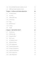
3.3 ASRock APP Shop 47 3.3.1 UI Overview 47 3.3.2 Apps 48 3.3.3 BIOS & Drivers 51 3.3.4 Setting 52 3.4 Start8 53 Chapter 4 UEFI SETUP UTILITY 56 4.1 Introduction 56 4.1.1 UEFI Menu Bar 56 4.1.2 Navigation Keys 57 4.2 Main Screen 58 4.3 OC Tweaker Screen 59 4.4 Advanced Screen - ASRock X99 Extreme4 | User Manual - Page 6
4.4.7 Trusted Computing 76 4.5 Tools 77 4.6 Hardware Health Event Monitoring Screen 81 4.7 Security Screen 83 4.8 Boot Screen 84 4.9 Exit Screen 87 - ASRock X99 Extreme4 | User Manual - Page 7
. You may ind the latest VGA cards and CPU support list on ASRock's website as well. ASRock website http://www.asrock.com. 1.1 Package Contents • ASRock X99 Extreme4 Motherboard (ATX Form Factor) • ASRock X99 Extreme4 Quick Installation Guide • ASRock X99 Extreme4 Support CD • 1 x I/O Panel Shield - ASRock X99 Extreme4 | User Manual - Page 8
Glass Fabric PCB CPU • Supports Intel® CoreTM i7 and Xeon® 18-Core Processors Family for the LGA 2011-3 Socket • Digi Power design • 12 Power Phase design • Supports Intel® Turbo Boost 2.0 Technology • Supports Untied Overclocking Technology Chipset • Intel® X99 Memory • Quad Channel DDR4 - ASRock X99 Extreme4 | User Manual - Page 9
Optical SPDIF Out Port • 4 x USB 2.0 Ports (Supports ESD Protection (ASRock Full Spike Protection)) • 4 x USB 3.0 Ports (Supports ESD Protection (ASRock Full Spike Protection)) • 1 x RJ-45 LAN Port with LED (ACT/LINK LED and SPEED LED) • 1 x Clear CMOS Switch • HD Audio Jacks: Rear Speaker / Central - ASRock X99 Extreme4 | User Manual - Page 10
3.0 ports) (Supports ESD Protection (ASRock Full Spike Protection)) BIOS Feature • 2 x 128Mb AMI UEFI Legal BIOS with multilingual GUI support (1 x Main BIOS and 1 x Backup BIOS) • Supports Secure Backup UEFI Technology • ACPI 1.1 Compliant wake up events • SMBIOS 2.3.1 Support • CPU, DRAM, PCH - ASRock X99 Extreme4 | User Manual - Page 11
damage caused by overclocking. Due to limitation, the actual memory size may be less than 4GB for the reservation for system usage under Windows® 32-bit operating systems. Windows® 64-bit operating systems do not have such limitations. You can use ASRock XFast RAM to utilize the memory that Windows - ASRock X99 Extreme4 | User Manual - Page 12
USB3_4_5 1 31 30 LAN PCIE_PWR1 PCIE1 PWR_FAN1 Ultra M.2 PCIe Gen3 x4 M2_1 CT5 CT4 CT3 X99 Extreme4 CT2 CT1 29 Purity SoundTM 2 PCIE2 RoHS PCIE3 1 T BT1 PCIE4 CMOS Battery Super I/O HD_AUDIO1 1 1 TPMS1 PCIE5 COM1 1 CLRMOS1 BIOS_SEL1 1 1 1 USB6_7 USB4_5 1 28 27 26 25 24 - ASRock X99 Extreme4 | User Manual - Page 13
(USB6_7) 24 BIOS Selection Jumper (BIOS_SEL1) 25 Clear CMOS Jumper (CLRCMOS1) 26 COM Port Header (COM1) 27 TPM Header (TPMS1) 28 Front Panel Audio Header (HD_AUDIO1) 29 hunderbolt AIC Connector (TBT1) 30 PCIe Power Connector (PCIE_PWR1) 31 Power Fan Connector (PWR_FAN1) X99 Extreme4 7 English - ASRock X99 Extreme4 | User Manual - Page 14
(Lime)** 8 Microphone (Pink) No. Description 9 Optical SPDIF Out Port 10 USB 3.0 Ports (USB3_23) 11 USB 3.0 Ports (USB3_01) 12 eSATA Connector*** 13 USB 2.0 Ports (USB01) 14 Clear CMOS Switch 15 PS/2 Keyboard Port English 8 - ASRock X99 Extreme4 | User Manual - Page 15
X99 Extreme4 * here are two LEDs on each LAN port. Please refer to the table below for the , or select "Realtek HDA Audio 2nd output" to use the front panel audio. *** he eSATA connector supports SATA with cables within 1 meters. he S_SATA3_3 connector is shared with the eSATA port English 9 - ASRock X99 Extreme4 | User Manual - Page 16
is an ATX form factor motherboard. Before you install the motherboard, study the coniguration of your chassis to ensure that the motherboard its into it. Pre-installation Precautions Take note of the following precautions before you install motherboard components or change any motherboard settings - ASRock X99 Extreme4 | User Manual - Page 17
if above situation is found. Otherwise, the CPU will be seriously damaged. 2. Unplug all power cables before installing the CPU. CAUTION: Please note that X99 platform is only compatible with the LGA 2011-3 socket, which is incompatible with the LGA 2011 socket (for X79 platform). 1 A B A 2 B 11 - ASRock X99 Extreme4 | User Manual - Page 18
A 3 B 4 5 12 English - ASRock X99 Extreme4 | User Manual - Page 19
X99 Extreme4 6 A B 7 A B 8 Please save and replace the cover if the processor is removed. he cover must be placed if you wish to return the motherboard for ater service. 13 English - ASRock X99 Extreme4 | User Manual - Page 20
2.2 Installing the CPU Fan and Heatsink 1 14 2 CPU_FAN English - ASRock X99 Extreme4 | User Manual - Page 21
X99 Extreme4 2.3 Installation of Memory Modules (DIMM) his motherboard provides eight 284-pin DDR4 (Double Data Rate 4) DIMM slots, and supports Quad Channel Memory Populated Populated Populated • Due to Intel® CPU spec deinition, please install the memory modules on DDR4_A1, DDR4_B1, DDR4_C1 and - ASRock X99 Extreme4 | User Manual - Page 22
1 2 3 16 English - ASRock X99 Extreme4 | User Manual - Page 23
X99 Extreme4 2.4 Expansion Slots (PCI Express Slots) here are 5 PCI Express slots on the motherboard. Before installing an PCI Express module is installed, PCIE5 will be disabled. PCIe Slot Conigurations (For CPU with 40 PCIe lanes) Single Graphics Card PCIE1 x16 PCIE2 N/A PCIE3 N/A PCIE4 - ASRock X99 Extreme4 | User Manual - Page 24
in 3-Way CrossFireXTM Mode x16 N/A x8 N/A x4 *3-Way SLITM Mode is not supported for CPU with 28 PCIe lanes. For a better thermal environment, please connect a chassis fan to the motherboard's chassis fan connector (CHA_FAN1, CHA_FAN2 or CHA_FAN3) when using multiple graphics cards. English - ASRock X99 Extreme4 | User Manual - Page 25
X99 Extreme4 2.5 Jumpers Setup he illustration shows how jumpers are setup. When the jumper cap is clear the CMOS right ater you update the BIOS. If you need to clear the CMOS when you just inish updating the BIOS, you must boot up the system irst, and then shut it down before you do the clear-CMOS - ASRock X99 Extreme4 | User Manual - Page 26
take over on the next system boot. Ater that, short pin1 and pin2 again, then use "Secure Backup UEFI" in BIOS setup utility to copy the BIOS ile to the main BIOS to ensure normal system operation. For the sake of system safety, users cannot update the backup BIOS manually. Users may refer to the - ASRock X99 Extreme4 | User Manual - Page 27
X99 Extreme4 2.6 Onboard Headers and Connectors Onboard headers and connectors are NOT jumpers. Do NOT place jumper caps over these headers and connectors. Placing jumper caps over the headers and connectors will cause permanent damage to the motherboard. System Panel Header (9-pin PANEL1) (see - ASRock X99 Extreme4 | User Manual - Page 28
Ultra M.2 Socket has been occupied, the internal S_SATA3_2 will not function. * RAID is supported on SATA3_0 ~ SATA3_5 ports only. SATA3_5 SATA3_3 SATA3_4 SATA3_2 USB 2.0 Headers (9- are two headers on this motherboard. Each USB 2.0 header can support two ports. Vbus IntA_PA_SSRXIntA_PA_SSRX+ - ASRock X99 Extreme4 | User Manual - Page 29
for connecting audio devices to the front audio panel. 1. High Deinition Audio supports Jack Sensing, but the panel wire on the chassis must support HDA to function correctly. Please follow the instructions in our manual and chassis manual to install your system. 2. If you use an AC'97 audio panel - ASRock X99 Extreme4 | User Manual - Page 30
12V CPU_FAN_SPEED FAN_SPEED_CONTROL GND FAN_VOLTAGE CPU_FAN_SPEED his motherboard provides a 4-Pin CPU fan (Quiet Fan) connector. If you plan to connect a 3-Pin CPU fan, please connect it to Pin 1-3. ATX Power Connector (24-pin ATXPWR1) (see p.6, No. 8) ATX 12V Power Connector (8-pin ATX12V1) (see - ASRock X99 Extreme4 | User Manual - Page 31
X99 Extreme4 Serial Port Header (9-pin COM1) (see p.6, No. 26) TPM Header (17-pin TPMS1) (see p.6, No. 27) 1 GN D SMB_CLK_MAIN SMB_DATA_MAIN LAD2 LAD1 GN D S_PWRDWN # SERIRQ # GND RRXD1 DDTR#1 DDSR#1 CCTS#1 1 RRI#1 RRTS#1 GND TTXD1 DDCD#1 his COM1 header supports a serial port module. his - ASRock X99 Extreme4 | User Manual - Page 32
2.7 Smart Switches he motherboard has a Clear CMOS Switch, allowing users to clear the CMOS values. Clear CMOS Switch (CLRCBTN) (see p.8, No. 14) Clear CMOS Switch allows users to quickly clear the CMOS values. his function is workable only when you power of your computer and unplug the power - ASRock X99 Extreme4 | User Manual - Page 33
X99 Extreme4 2.8 SLITM , 3-Way SLITMand Quad SLITM Operation Guide his motherboard supports NVIDIA® SLITM , 3-Way SLITM and Quad SLITM (Scalable Link Interface) technology that allows you to install up to three identical PCI Express x16 graphics cards. - ASRock X99 Extreme4 | User Manual - Page 34
SLI_ Bridge_2S Card to the goldingers on each graphics card. Make sure the ASRock SLI_ Bridge_2S Card is irmly in place. SLI_Bridge_2S Card ASRock SLI_Bridge_2S Card Step 4 Connect a VGA cable or a DVI cable to the monitor connector or the DVI connector of the graphics card that is inserted to - ASRock X99 Extreme4 | User Manual - Page 35
X99 Extreme4 2.8.2 Installing Three SLITM-Ready Graphics Cards Step 1 Insert one graphics card on the three graphics cards. Step 3 Align and insert the ASRock 3-Way SLI2S1S Bridge Card to the goldingers on each graphics card. Make sure the ASRock 3-Way SLI-2S1S Bridge Card is irmly in place. 3-Way - ASRock X99 Extreme4 | User Manual - Page 36
Step 4 Connect a VGA cable or a DVI cable to the monitor connector or the DVI connector of the graphics card that is inserted to PCIE1 slot. 30 English - ASRock X99 Extreme4 | User Manual - Page 37
X99 Extreme4 2.8.3 Driver Installation and Setup Install the graphics card drivers to your system. Ater that, you can enable the the Windows® system tray. Step 2 In the let pane, click Set SLI and PhysX coniguration. hen select Maximize 3D performance and click Apply. Step 3 Reboot your system - ASRock X99 Extreme4 | User Manual - Page 38
CrossFireXTM Operation Guide his motherboard supports CrossFireXTM, 3-way Make sure that your graphics card driver supports AMD CrossFireXTM technology. Download the drivers from the AMD's website: www. to AMD graphics card manuals for detailed installation guide. 2.9.1 Installing Two CrossFireXTM - ASRock X99 Extreme4 | User Manual - Page 39
X99 Extreme4 Step 3 Connect a VGA cable or a DVI cable to the monitor connector or the DVI connector of the graphics card that is inserted to PCIE1 slot. 33 English - ASRock X99 Extreme4 | User Manual - Page 40
to connect the graphics cards on PCIE3 and PCIE5 slots. (he CrossFire Bridge is provided with the graphics card you purchase, not bundled with this motherboard. Please refer to your graphics card vendor for details.) Step 3 Connect a VGA cable or a DVI cable to the monitor connector or the DVI - ASRock X99 Extreme4 | User Manual - Page 41
X99 Extreme4 2.9.3 Driver Installation and Setup Step 1 Power on your computer and boot into OS. Step 2 Remove the AMD drivers if you have any VGA drivers Catalyst drivers prior to installation. Please check AMD's website for AMD driver updates. Step 3 Install the required drivers and CATALYST - ASRock X99 Extreme4 | User Manual - Page 42
2.10 M.2_SSD (NGFF) Module Installation Guide he M.2, also known as the Next Generation Form Factor (NGFF), is a small size and versatile card edge connector that aims to replace mPCIe and mSATA. - ASRock X99 Extreme4 | User Manual - Page 43
B A C B A E D C B A E D NUT2 NUT1 X99 Extreme4 Step 3 Move the standof based on the module type and length. he nut location on the motherboard. Step 5 Align and gently insert the M.2 (NGFF) SSD module into the M.2 slot. Please be aware that the M.2 (NGFF) SSD module only its in - ASRock X99 Extreme4 | User Manual - Page 44
M.2_SSD (NGFF) Module Support List PCIe Interface SATA Interface Plextor PX-G512M6e Plextor PX-G256M6e SanDisk SSDSCKGW080A401/80G Kingston RBU-SM2280S3/120G For the latest updates of M.2_SSD (NFGG) module support list, please visit our website for details: http://www.asrock.com English 38 - ASRock X99 Extreme4 | User Manual - Page 45
X99 Extreme4 2.11 HDD Saver Cable Installation Guide The HDD Saver Connector on this motherboard allows you to switch on SATA HDD(s). * he HDD Saver Connector supports up to two SATA HDDs. 2. Connect one end of the SATA data cable to a SATA port on the motherboard. hen connect the other end to your - ASRock X99 Extreme4 | User Manual - Page 46
Chapter 3 Software and Utilities Operation 3.1 Installing Drivers he Support CD that comes with the motherboard contains necessary drivers and useful utilities that enhance the motherboard's features. Running The Support CD To begin using the support CD, insert the CD into your CD-ROM drive. he CD - ASRock X99 Extreme4 | User Manual - Page 47
RAM, Dehumidiier, Good Night LED, FAN-Tastic Tuning, OC Tweaker and a whole lot more. 3.2.1 Installing A-Tuning When you install the all-in-one driver to your system from ASRock's support System Info, Live Update, Tech Service and Settings. Operation Mode Choose an operation mode for your computer. - ASRock X99 Extreme4 | User Manual - Page 48
should be stored in the RAM drive. XFast LAN Boost the speed of your internet connection! Select a speciic mode for making the designated program's priority highest. Fast Boot Fast Boot minimizes your computer's boot time. Please note that Ultra Fast mode is only supported by Windows 8.1/8 and the - ASRock X99 Extreme4 | User Manual - Page 49
X99 Extreme4 FAN-Tastic Tuning Conigure up to ive diferent fan speeds using the graph. he fans will automatically shit to the next speed level when the assigned temperature is met. Dehumidiier Prevent motherboard , etc. HDD, SSD and optical disk drives are all supported. he health status block - ASRock X99 Extreme4 | User Manual - Page 50
OC Tweaker Conigurations for overclocking the system. System Info View information about the system. *he System Browser tab may not appear for certain models. 44 English - ASRock X99 Extreme4 | User Manual - Page 51
Live Update Check for newer versions of BIOS or drivers. X99 Extreme4 Tech Service Contact Tech Service if you have problems with your computer. Please leave your contact information along with details of the problem. English 45 - ASRock X99 Extreme4 | User Manual - Page 52
Settings Conigure ASRock A-Tuning. Click to select "Auto run at Windows Startup" if you want A-Tuning to be launched when you start up the Windows operating system. 46 English - ASRock X99 Extreme4 | User Manual - Page 53
X99 Extreme4 3.3 ASRock APP Shop he ASRock APP Shop is an online store for purchasing and downloading sotware applications for your ASRock computer. You can install various apps and support utilities quickly and easily, and optimize your system and keep your motherboard up to date simply with a few - ASRock X99 Extreme4 | User Manual - Page 54
want to install. he most recommended app appears on the let side of the screen. he other various apps are shown on the right. Please scroll up and down to see more apps listed. You can check the price of the app and whether you have already intalled it or not. - he - ASRock X99 Extreme4 | User Manual - Page 55
X99 Extreme4 Step 3 If you want to install the app, click on the red icon to start downloading. Step 4 When installation completes, you can ind the green " - ASRock X99 Extreme4 | User Manual - Page 56
Upgrading an App You can only upgrade the apps you have already installed. When there is an available new version for your app, you will ind the mark of "New Version" appears below the installed app icon. Step 1 Click on the app icon to see more details. Step 2 Click on the yellow icon to start - ASRock X99 Extreme4 | User Manual - Page 57
X99 Extreme4 3.3.3 BIOS & Drivers Installing BIOS or Drivers When the "BIOS & Drivers" tab is selected, you will see a list of recommended or critical updates for the BIOS or drivers. Please update them all soon. Step 1 Please check the item information before update. Click on Step 2 to see more - ASRock X99 Extreme4 | User Manual - Page 58
3.3.4 Setting In the "Setting" page, you can change the language, select the server location, and determine if you want to automatically run the ASRock APP Shop on Windows startup. 52 English - ASRock X99 Extreme4 | User Manual - Page 59
X99 Extreme4 3.4 Start8 For those Windows 8 users who miss the Start Menu, Start8 is Installing Start8 Install Start8, which is located in the folder at the following path of the Support CD: \ ASRock Utility > Start8. 3.4.2 Coniguring Start8 Style Select between the Windows 7 style and Windows 8 - ASRock X99 Extreme4 | User Manual - Page 60
Conigure Conigure provides coniguration options, including icon sizes, which shortcuts you want Start Menu to display, quick access to recently used apps, the functionality of the power button, and more. Control 54 English - ASRock X99 Extreme4 | User Manual - Page 61
X99 Extreme4 Control lets you conigure what a click on the start button or a press on the Windows key does. Desktop Desktop allows you to disable the hot corners when you are working on the desktop. It also lets you choose whether or not the system boots directly into desktop mode and bypass the - ASRock X99 Extreme4 | User Manual - Page 62
For overclocking conigurations Advanced For advanced system conigurations Tool Useful tools H/W Monitor Displays current hardware status Boot For coniguring boot settings and boot priority Security For security settings Exit Exit the current screen or the UEFI Setup Utility English - ASRock X99 Extreme4 | User Manual - Page 63
X99 Extreme4 4.1.2 Navigation Keys Use < > key or < > key to choose among the selections on the menu bar, and use < > key or < > key to move the cursor up or down to select items, then press to get into the sub screen. You can also use the mouse to click your required item. Please check - ASRock X99 Extreme4 | User Manual - Page 64
HD resolution. If the monitor does not support Full HD resolution, then the resolution will be set to 1024 x 768. When [Disable] is selected, the resolution will be set to 1024 x 768 directly. UEFI Guide UEFI Guide is a quick tutorial for ASRock's UEFI setup Utility. You may abort the tutorial by - ASRock X99 Extreme4 | User Manual - Page 65
Tweaker screen, you can set up overclocking features. X99 Extreme4 Because the UEFI sotware is constantly being updated, the following UEFI setup screens and descriptions are for reference purpose only, and they may not exactly match what you see on your screen. Load Optimized CPU OC Setting You - ASRock X99 Extreme4 | User Manual - Page 66
Intel Turbo Boost Technology enables the processor to run above its base operating frequency when the operating system requests the highest performance state. Filter PLL Frequency CPU BCLK Filter Frequency. Choose 1.6 for better overclocking capabilities. Long Duration Power Limit Conigure - ASRock X99 Extreme4 | User Manual - Page 67
X99 Extreme4 Primary Plane Current Limit Conigure the current limit of the CPU under Turbo Mode in ampere. A lower limit can protect the CPU and save power, while a higher limit may improve performance. DRAM Timing Coniguration DRAM Reference Clock Select Auto for optimized settings. DRAM Frequency - ASRock X99 Extreme4 | User Manual - Page 68
and the beginning of the data in response. RAS# to CAS# Delay (tRCD) he number of clock cycles required between the opening of a row of memory and accessing columns within it. Row Precharge Time (tRP) he number of clock cycles required between the issuing of the precharge command and opening the - ASRock X99 Extreme4 | User Manual - Page 69
X99 Extreme4 Write to Read Delay (tWTR_L) he number of clocks between the last valid write operation and the next read command to the same internal bank. - ASRock X99 Extreme4 | User Manual - Page 70
resistors' WR for channel A. ODT PARK (CH A) Conigure the memory on die termination resistors' PARK for channel A. ODT NOM (CH A) Use this to change ODT (CH A) Auto/Manual settings. he default is [Auto]. ODT WR (CH B) Conigure the memory on die termination resistors' WR for channel B. 64 English - ASRock X99 Extreme4 | User Manual - Page 71
X99 Extreme4 ODT PARK (CH B) Conigure the memory on die termination resistors' PARK for channel B. ODT NOM (CH B) Use this to change ODT (CH B) Auto/Manual settings. he default is [Auto]. ODT WR (CH C) Conigure the memory on die termination resistors' WR for channel C. ODT PARK (CH C) Conigure the - ASRock X99 Extreme4 | User Manual - Page 72
System Agent Voltage Ofset Conigure the voltage for the System Agent. Setting the voltage higher may increase system stability when overclocking. CPU Integrated VR Faults Disable FIVR Faults to raise the threshold to trigger CPU over current protection and over voltage protection for better - ASRock X99 Extreme4 | User Manual - Page 73
X99 Extreme4 4.4 Advanced Screen In this section, you may set the conigurations for the following items: CPU Coniguration, Chipset Coniguration, Storage Coniguration, Super IO Coniguration, ACPI Coniguration, USB Coniguration and Trusted Computing. Setting wrong values in this section may cause the - ASRock X99 Extreme4 | User Manual - Page 74
cores to enable in each processor package. No-Execute Memory Protection Processors with No-Execution Memory Protection Technology may prevent certain classes of malicious bufer overlow attacks. Hardware Prefetcher Automatically prefetch data and code for the processor. Enable for better performance - ASRock X99 Extreme4 | User Manual - Page 75
X99 Extreme4 CPU Thermal Throttling Enable CPU internal thermal control mechanisms to keep the CPU from overheating. CPU C States Support Enable CPU C States Support for power saving. It is recommended to keep C3, C6 and C7 all enabled for better power saving. Package C State Support Enable CPU, - ASRock X99 Extreme4 | User Manual - Page 76
4.4.2 Chipset Coniguration Intel(R) Thunderbolt Enable/Disable the Intel(R) hunderbolt function. VT-d Intel® Virtualization Technology for Directed I/O helps your virtual machine monitor better utilize hardware by improving application compatibility and reliability, and providing additional levels - ASRock X99 Extreme4 | User Manual - Page 77
X99 Extreme4 Onboard LAN Enable or disable the onboard network interface controller. Onboard HD Audio Enable/disable onboard HD audio. Set to Auto the power recovers. If [Power On] is selected, the system will start to boot up when the power recovers. Good Night LED By enabling Good Night LED, the - ASRock X99 Extreme4 | User Manual - Page 78
4.4.3 Storage Coniguration Hard Disk S.M.A.R.T. S.M.A.R.T stands for Self-Monitoring, Analysis, and Reporting Technology. It is a monitoring system for computer hard disk drives to detect and report on various indicators of reliability. 72 English - ASRock X99 Extreme4 | User Manual - Page 79
4.4.4 Super IO Coniguration X99 Extreme4 Serial Port Enable or disable the Serial port. Serial Port Address Select the address of the Serial port. 73 English - ASRock X99 Extreme4 | User Manual - Page 80
4.4.5 ACPI Coniguration Suspend to RAM Select disable for ACPI suspend type S1. It is recommended to select auto signals. RTC Alarm Power On Allow the system to be waked up by the real time clock alarm. Set it to By OS to let it be handled by your operating system. USB Keyboard/Remote Power On Allow - ASRock X99 Extreme4 | User Manual - Page 81
USB Coniguration X99 Extreme4 USB Controller Enable or disable all the USB ports. Intel USB 3.0 Mode Select Intel® USB 3.0 controller mode. Set [Smart Auto] to keep the USB 3.0 driver enabled ater rebooting (USB 3.0 is enabled in BIOS). Set [Auto] to automatically enable the USB 3.0 driver ater - ASRock X99 Extreme4 | User Manual - Page 82
4.4.7 Trusted Computing Security Device Support Enable or disable BIOS support for security device. 76 English - ASRock X99 Extreme4 | User Manual - Page 83
4.5 Tools X99 Extreme4 System Browser ASRock System Browser shows the overview of your current PC and the devices connected. OMG (Online Management Guard) Administrators are able to establish an internet curfew - ASRock X99 Extreme4 | User Manual - Page 84
Dehumidiier CPU Fan Setting Conigure the speed of the CPU fan while Dehumidiier is enabled. he higher the value, save more energy, and prolong your HDDs' life spans. HDD Saver Technology Set [Enabled] to switch on the HDD Saver. Set [Disabled] to switch of the HDD Saver. It is recommended to enable - ASRock X99 Extreme4 | User Manual - Page 85
an USB storage device, then downloads and installs the other required drivers automatically. UEFI Tech Service Contact ASRock Tech Service if you are having trouble with your PC. Please setup network coniguration before using UEFI Tech Service. Instant Flash Save UEFI iles in your USB storage device - ASRock X99 Extreme4 | User Manual - Page 86
Network Coniguration Use this to conigure internet connection settings for Internet Flash. Internet Setting Enable or disable sound efects in the setup utility. UEFI Download Server Select a server to download the UEFI irmware. Save User Default Type a proile name and press enter to save your - ASRock X99 Extreme4 | User Manual - Page 87
X99 Extreme4 4.6 Hardware Health Event Monitoring Screen his section allows you to monitor the status of the hardware on your system, including the parameters of the CPU temperature, motherboard temperature, fan speed and voltage. CPU Fan 1 & 2 Setting Select a fan mode for CPU Fans 1&2, or choose - ASRock X99 Extreme4 | User Manual - Page 88
to set 5 CPU temperatures and assign a respective fan speed for each temperature. Chassis Fan 3 Temp Source Select a fan temperature source for Chassis Fan 3. Over Temperature Protection When Over Temperature Protection is enabled, the system automatically shuts down when the motherboard - ASRock X99 Extreme4 | User Manual - Page 89
X99 Extreme4 4.7 Security Screen In this section you may set or change the supervisor/user password for the system. You may also clear the user password. Supervisor Password Set or change the password for the administrator account. Only the administrator has authority to change the settings in the - ASRock X99 Extreme4 | User Manual - Page 90
device. Ultra Fast mode is only supported by Windows 8.1/8 and the VBIOS must support UEFI GOP if you are using an external graphics card. Please notice that Ultra Fast mode will boot so fast that the only way to enter this UEFI Setup Utility is to Clear CMOS or run the Restart to UEFI utility - ASRock X99 Extreme4 | User Manual - Page 91
X99 Extreme4 Full Screen Logo Enable to display the boot logo or disable to show normal POST messages. AddOn ROM Display Enable AddOn ROM Display to see the AddOn ROM messages or conigure the AddOn ROM if you've enabled Full Screen Logo. Disable for faster boot speed. Boot Failure Guard If the - ASRock X99 Extreme4 | User Manual - Page 92
Module) CSM Enable to launch the Compatibility Support Module. Please do not disable unless you're running a WHCK test. If you are using Windows 8.1/8 64-bit and all of your devices support UEFI, you may also disable CSM for faster boot speed. Launch PXE OpROM Policy Select UEFI only to run those - ASRock X99 Extreme4 | User Manual - Page 93
4.9 Exit Screen X99 Extreme4 Save Changes and Exit When you select this option the following message, "Save coniguration changes and exit setup?" will pop out. Select [OK] to save changes and exit the UEFI SETUP UTILITY. Discard Changes and Exit When you select this option the following message, " - ASRock X99 Extreme4 | User Manual - Page 94
or want to know more about ASRock, you're welcome to visit ASRock's website at http://www.asrock.com; or you may contact your dealer for further information. For technical questions, please submit a support request form at http://www.asrock.com/support/tsd.asp ASRock Incorporation 2F., No.37, Sec
-
 1
1 -
 2
2 -
 3
3 -
 4
4 -
 5
5 -
 6
6 -
 7
7 -
8
-
9
-
10
-
11
-
12
-
13
-
14
-
15
-
16
-
17
-
18
-
19
-
20
-
21
-
22
-
23
-
24
-
25
-
26
-
27
-
28
-
29
-
30
-
31
-
32
-
33
-
34
-
35
-
36
-
37
-
38
-
39
-
40
-
41
-
42
-
43
-
44
-
45
-
46
-
47
-
48
-
49
-
50
-
51
-
52
-
53
-
54
-
55
-
56
-
57
-
58
-
59
-
60
-
61
-
62
-
63
-
64
-
65
-
66
-
67
-
68
-
69
-
70
-
71
-
72
-
73
-
74
-
75
-
76
-
77
-
78
-
79
-
80
-
81
-
82
-
83
-
84
-
85
-
86
-
87
-
88
-
89
-
90
-
91
-
92
-
93
-
94
 |
 |

X99 Extreme4
X99 Extreme4