ASRock X99 Extreme6/3.1 User Manual
ASRock X99 Extreme6/3.1 Manual
 |
View all ASRock X99 Extreme6/3.1 manuals
Add to My Manuals
Save this manual to your list of manuals |
ASRock X99 Extreme6/3.1 manual content summary:
- ASRock X99 Extreme6/3.1 | User Manual - Page 1
X99 Extreme46/3.1 User Manual - ASRock X99 Extreme6/3.1 | User Manual - Page 2
change without notice, and should not be constructed as a commitment by ASRock. ASRock assumes no responsibility for any errors or omissions that may appear in CALIFORNIA, USA ONLY he Lithium battery adopted on this motherboard contains Perchlorate, a toxic substance controlled in Perchlorate Best - ASRock X99 Extreme6/3.1 | User Manual - Page 3
Manufactured under license under U.S. Patent Nos: 5,956,674; 5,974,380; 6,487,535; 7,003,467 & other U.S. and worldwide patents issued & pending. DTS, the Symbol, & DTS and the Symbol together is a registered trademark & DTS Connect, DTS Interactive, DTS Neo:PC are trademarks of DTS, Inc. Product - ASRock X99 Extreme6/3.1 | User Manual - Page 4
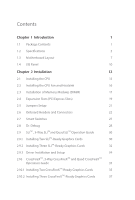
1 Introduction 1 1.1 Package Contents 1 1.2 Speciications 2 1.3 Motherboard Layout 7 1.4 I/O Panel 10 Chapter 2 Installation 12 2.1 . Debug 28 2.9 SLITM , 3-Way SLITMand Quad SLITM Operation Guide 30 2.9.1 Installing Two SLITM-Ready Graphics Cards 30 2.9.2 Installing Three - ASRock X99 Extreme6/3.1 | User Manual - Page 5
2.12 HDD Saver Cable Installation Guide 42 2.13 ASRock USB 3.1 Card/A+A Installation Guide 43 Chapter 3 Software and Utilities Operation 45 3.1 Installing Drivers 45 3.2 A-Tuning 46 3.3 ASRock APP Shop 52 3.3.1 UI Overview 52 3.3.2 Apps 53 3.3.3 BIOS & Drivers 56 3.3.4 Setting 57 - ASRock X99 Extreme6/3.1 | User Manual - Page 6
4.4.5 ACPI Coniguration 81 4.4.6 USB Coniguration 82 4.4.7 Trusted Computing 83 4.5 Tools 84 4.6 Hardware Health Event Monitoring Screen 89 4.7 Security Screen 91 4.8 Boot Screen 92 4.9 Exit Screen 95 - ASRock X99 Extreme6/3.1 | User Manual - Page 7
CPU support list on ASRock's website as well. ASRock website http://www.asrock.com. 1.1 Package Contents • ASRock X99 Extreme6/3.1 Motherboard (ATX Form Factor) • ASRock X99 Extreme6/3.1 Quick Installation Guide • ASRock X99 Extreme6/3.1 Support CD • 1 x I/O Panel Shield • 1 x ASRock USB 3.1 Card - ASRock X99 Extreme6/3.1 | User Manual - Page 8
un-bufered memory * Please refer to Memory Support List on ASRock's website for more information. (http://www.asrock.com/) • Supports non-ECC RDIMM (Registered DIMM) • Supports DDR4 ECC, un-bufered memory/RDIMM with Intel® Xeon® processors E5 series in the LGA 2011-3 Socket • Max. capacity of system - ASRock X99 Extreme6/3.1 | User Manual - Page 9
X99 Extreme6/3.1 • Supports NVIDIA® Quad SLITM, 3-Way SLITM and SLITM * If you install CPU with 28 lanes, 3-Way SLITM is not supported. Audio • 7.1 CH HD Audio with Content Protection (Realtek ALC1150 Audio Codec) • Premium Blu-ray Audio support • Supports Surge Protection (ASRock Full Spike - ASRock X99 Extreme6/3.1 | User Manual - Page 10
x 24 pin ATX Power Connector • 1 x 8 pin 12V Power Connector (Hi-Density Power Connector) • 1 x HDD Saver Connector • 1 x PCIe Power Connector • 1 x Front Panel Audio Connector • 1 x hunderbolt AIC Connector • 2 x USB 2.0 Headers (support 4 USB 2.0 ports) (Supports ESD Protection (ASRock Full Spike - ASRock X99 Extreme6/3.1 | User Manual - Page 11
X99 Extreme6/3.1 BIOS Feature Hardware Monitor OS Certiications • 2 x USB 3.0 Headers (Support 4 USB 3.0 ports) (Supports ESD Protection (ASRock Full Spike Protection)) • 1 x Dr. Debug with LED • 1 x Power Switch with LED • 1 x Reset Switch with LED • 1 x BIOS Selection Switch • 2 x 128Mb AMI UEFI - ASRock X99 Extreme6/3.1 | User Manual - Page 12
a certain risk involved with overclocking, including adjusting the setting in the BIOS, applying Untied Overclocking Technology, or using third-party overclocking tools. Overclocking not have such limitations. You can use ASRock XFast RAM to utilize the memory that Windows® cannot use. 6 English - ASRock X99 Extreme6/3.1 | User Manual - Page 13
X99 Extreme6/3.1 1.3 Motherboard Layout 12 3 4 56 7 USB 2.0 T: USB1 B: USB2 PS2 Keyboard /Mouse CLRC BTN1 USB 3.1 (Type-C) Vertical Type A USB -pin module) DDR4_B2 (64 bit, 288-pin module) 2011-3 Socket 9 USB 3.0 T: USB1 B: USB2 Top: RJ-45 USB 3.0 T: USB3 B: USB4 Top: RJ-45 Top: - ASRock X99 Extreme6/3.1 | User Manual - Page 14
DDR4_D1, DDR4_C1) 8 Vertical Type A USB 2.0 (USB7) 9 ATX Power Connector (ATXPWR1) 10 USB 3.0 Header (USB3_7_8) 11 USB 3.0 Header (USB3_5_6) 12 Chassis Fan 26 Chassis Fan Connector (CHA_FAN1) 27 USB 2.0 Header (USB3_4) 28 USB 2.0 Header (USB5_6) 29 BIOS Selection Switch (BIOS_SEL1) 30 Clear CMOS - ASRock X99 Extreme6/3.1 | User Manual - Page 15
No. Description 34 Front Panel Audio Header (HD_AUDIO1) 35 PCIe Power Connector (PCIE_PWR1) 36 Power Fan Connector (PWR_FAN1) X99 Extreme6/3.1 English 9 - ASRock X99 Extreme6/3.1 | User Manual - Page 16
Panel 1 46 2 3 57 15 14 13 12 11 10 98 No. Description 1 USB 2.0 Ports (USB12) 2 LAN RJ-45 Port (Qualcomm® Atheros® AR8171)* 3 LAN SPDIF Out Port 10 USB 3.0 Ports (USB3_34) (ASMedia ASM1074 hub) 11 USB 3.0 Ports (USB3_12) (ASMedia ASM1074 hub) 12 eSATA Connector*** 13 USB 3.1 Type-C Port - ASRock X99 Extreme6/3.1 | User Manual - Page 17
X99 Extreme6/3.1 * here are two LEDs on each LAN port. Please refer to the table below for the , or select "Realtek HDA Audio 2nd output" to use the front panel audio. *** he eSATA connector supports SATA with cables within 1 meters. he SSATA3_3 connector is shared with the eSATA port English 11 - ASRock X99 Extreme6/3.1 | User Manual - Page 18
2 Installation his is an ATX form factor motherboard. Before you install the motherboard, study the coniguration of your chassis to ensure that the motherboard its into it. Pre-installation Precautions Take note of the following precautions before you install motherboard components or change any - ASRock X99 Extreme6/3.1 | User Manual - Page 19
X99 Extreme6/3.1 2.1 Installing the CPU 1. Before you insert the 2011-3-Pin CPU into the socket, please cables before installing the CPU. CAUTION: Please note that X99 platform is only compatible with the LGA 2011-3 socket, which is incompatible with the LGA 2011 socket (for X79 platform). 1 A B A - ASRock X99 Extreme6/3.1 | User Manual - Page 20
A 3 B 4 5 14 English - ASRock X99 Extreme6/3.1 | User Manual - Page 21
X99 Extreme6/3.1 6 A B 7 A B 8 Please save and replace the cover if the processor is removed. he cover must be placed if you wish to return the motherboard for ater service. 15 English - ASRock X99 Extreme6/3.1 | User Manual - Page 22
2.2 Installing the CPU Fan and Heatsink 1 16 2 CPU_FAN English - ASRock X99 Extreme6/3.1 | User Manual - Page 23
X99 Extreme6/3.1 2.3 Installation of Memory Modules (DIMM) his motherboard provides eight 288-pin DDR4 (Double Data Rate 4) DIMM slots, and supports Quad Channel Memory Technology. 1. For quad channel coniguration, you always need to install identical (the same brand, speed, size and chip-type) - ASRock X99 Extreme6/3.1 | User Manual - Page 24
1 2 3 18 English - ASRock X99 Extreme6/3.1 | User Manual - Page 25
X99 Extreme6/3.1 2.4 Expansion Slots (PCI Express Slots) here are 5 PCI Express slots and 1 mini-PCI Express slot on the motherboard. Before installing an expansion card, please make sure that the power supply is switched of or the power cord is unplugged. Please read the documentation - ASRock X99 Extreme6/3.1 | User Manual - Page 26
in 3-Way CrossFireXTM Mode x16 N/A x8 N/A x4 *3-Way SLITM Mode is not supported for CPU with 28 PCIe lanes. For a better thermal environment, please connect a chassis fan to the motherboard's chassis fan connector (CHA_FAN1, CHA_FAN2 or CHA_FAN3) when using multiple graphics cards. English - ASRock X99 Extreme6/3.1 | User Manual - Page 27
X99 Extreme6/3.1 2.5 Jumpers Setup he illustration shows how jumpers are setup. When the jumper cap is . However, please do not clear the CMOS right ater you update the BIOS. If you need to clear the CMOS when you just inish updating the BIOS, you must boot up the system irst, and then shut it down - ASRock X99 Extreme6/3.1 | User Manual - Page 28
place jumper caps over these headers and connectors. Placing jumper caps over the headers and connectors will cause permanent damage to the motherboard. System Panel Header (9-pin PANEL1) (see p.7, No. 21) PLED+ PLEDPWRBTN# GND 1 GND RESET# GND HDLEDHDLED+ Connect the power switch, reset switch - ASRock X99 Extreme6/3.1 | User Manual - Page 29
SATA3_0 SSATA3_2 SSATA3_0 SATA3_3 SSATA3_3 SSATA3_1 X99 Extreme6/3.1 hese ten SATA3 connectors support SATA data cables for internal storage PUSB_PWR Besides two USB 2.0 ports on the I/O panel, there are two headers and one port on this motherboard. Each USB 2.0 header can support two ports. - ASRock X99 Extreme6/3.1 | User Manual - Page 30
1 here are two headers on this motherboard. Each USB 3.0 header can support two ports. Front Panel Audio Header Deinition Audio supports Jack Sensing, but the panel wire on the chassis must support HDA to function correctly. Please follow the instructions in our manual and chassis manual to - ASRock X99 Extreme6/3.1 | User Manual - Page 31
X99 Extreme6/3.1 (3-pin CHA_FAN3) (see p.7, No. 12) (3-pin PWR_FAN1) (see p.7, No. 36) GND motherboard provides a 24-pin ATX power connector. To use a 20-pin ATX power supply, please plug it along Pin 1 and Pin 13. his motherboard provides an 8-pin ATX 12V power connector. To use a 4-pin ATX - ASRock X99 Extreme6/3.1 | User Manual - Page 32
™ add-in card (AIC) to this connector via the GPIO cable. RRXD1 DDTR#1 DDSR#1 CCTS#1 1 RRI#1 RRTS#1 GND TTXD1 DDCD#1 his COM1 header supports a serial port module. TPM Header (17-pin TPMS1) (see p.7, No. 33) 1 GN D SMB_CLK_MAIN SMB_DATA_MAIN LAD2 LAD1 GN D S_PWRDWN # SERIRQ # GND his connector - ASRock X99 Extreme6/3.1 | User Manual - Page 33
X99 Extreme6/3.1 2.7 Smart Switches he motherboard has four smart switches: Power Switch, Reset Switch, Clear CMOS Switch and one BIOS Selection Switch, allowing users to quickly turn on/of the system, reset the system, clear the CMOS values or boot from diferent BIOS. Power Switch (PWRBTN) (see - ASRock X99 Extreme6/3.1 | User Manual - Page 34
. Debug is used to provide code information, which makes troubleshooting even easier. Please see the diagrams below for reading the Dr. Debug codes. Code Description 00 Please check if the CPU is installed correctly and then clear CMOS. 0d Problem related to memory, VGA card or other devices - ASRock X99 Extreme6/3.1 | User Manual - Page 35
X99 Extreme6/3.1 b4 Problem related to USB devices. Please try removing all USB devices. b7 Problem related to memory. Please re-install the CPU and memory then clear CMOS. If the problem still exists, please install only one memory module or try using other memory modules. d6 he VGA could - ASRock X99 Extreme6/3.1 | User Manual - Page 36
Quad SLITM Operation Guide his motherboard supports NVIDIA® SLITM , 3-Way SLITM and Quad SLITM (Scalable Link Interface) technology that allows you to install up to three identical PCI Express x16 graphics cards. Currently, NVIDIA® SLITM and Quad SLITM technology supports Windows® 7 / 7 64-bit - ASRock X99 Extreme6/3.1 | User Manual - Page 37
X99 Extreme6/3.1 Step 3 Align and insert the ASRock SLI_ Bridge_2S Card to the goldingers on each graphics card. Make sure the ASRock SLI_ Bridge_2S Card is irmly in place. SLI_Bridge_2S Card ASRock SLI_Bridge_2S Card Step 4 Connect a VGA cable or a DVI cable to the monitor connector or the DVI - ASRock X99 Extreme6/3.1 | User Manual - Page 38
graphics card are connected. Repeat this step on the three graphics cards. Step 3 Align and insert the ASRock 3-Way SLI2S1S Bridge Card to the goldingers on each graphics card. Make sure the ASRock 3-Way SLI-2S1S Bridge Card is irmly in place. 3-Way SLI-2S1S Bridge Card 32 3-Way SLI2S1S English - ASRock X99 Extreme6/3.1 | User Manual - Page 39
X99 Extreme6/3.1 Step 4 Connect a VGA cable or a DVI cable to the monitor connector or the DVI connector of the graphics card that is inserted to PCIE1 slot. 33 English - ASRock X99 Extreme6/3.1 | User Manual - Page 40
2.9.3 Driver Installation and Setup Install the graphics card drivers to your system. Ater that, you can enable the Multi-Graphics Processing Unit (GPU) in the NVIDIA® nView system tray utility. Please follow the below procedures to enable the multi-GPU. Step 1 Double-click the NVIDIA Control Panel - ASRock X99 Extreme6/3.1 | User Manual - Page 41
X99 Extreme6/3.1 2.10 CrossFireXTM, 3-Way CrossFireXTM and Quad CrossFireXTM Operation Guide his motherboard supports CrossFireXTM, 3-way enable CrossFireXTM. Please refer to AMD graphics card manuals for detailed installation guide. 2.10.1 Installing Two CrossFireXTM-Ready Graphics Cards - ASRock X99 Extreme6/3.1 | User Manual - Page 42
Step 3 Connect a VGA cable or a DVI cable to the monitor connector or the DVI connector of the graphics card that is inserted to PCIE1 slot. 36 English - ASRock X99 Extreme6/3.1 | User Manual - Page 43
X99 Extreme6/3.1 2.10.2 Installing Three CrossFireXTM-Ready Graphics Cards Step 1 Insert one PCIE5 slots. (he CrossFire Bridge is provided with the graphics card you purchase, not bundled with this motherboard. Please refer to your graphics card vendor for details.) Step 3 Connect a VGA cable or a - ASRock X99 Extreme6/3.1 | User Manual - Page 44
2.10.3 Driver Installation and Setup Step 1 Power on your computer and boot into OS. Step 2 Remove the AMD drivers if you have any VGA drivers installed in your system. he Catalyst Uninstaller is an optional download. We recommend using this utility to uninstall any previously installed Catalyst - ASRock X99 Extreme6/3.1 | User Manual - Page 45
X99 Extreme6/3.1 2.11 M.2_SSD (NGFF) Module Installation Guide he M.2, also known as the Next Generation Form Factor (NGFF), is a small size and versatile card edge connector that aims to replace mPCIe and mSATA. - ASRock X99 Extreme6/3.1 | User Manual - Page 46
hand. Step 4 Peel of the yellow protective ilm on the nut to be used. Hand tighten the standof into the desired nut location on the motherboard. Step 5 Align and gently insert the M.2 (NGFF) SSD module into the M.2 slot. Please be aware that the M.2 (NGFF) SSD module only its in one orientation - ASRock X99 Extreme6/3.1 | User Manual - Page 47
X99 Extreme6/3.1 M.2_SSD (NGFF) Module Support List PCIe Interface SATA Interface Plextor PX-G512M6e Plextor PX-G256M6e SanDisk Kingston RBU-SM2280S3/120G For the latest updates of M.2_SSD (NFGG) module support list, please visit our website for details: http://www.asrock.com English 41 - ASRock X99 Extreme6/3.1 | User Manual - Page 48
2.12 HDD Saver Cable Installation Guide The HDD Saver Connector on this motherboard allows you to switch on and off your SATA HDD(s). * he HDD Saver Connector supports up to two SATA HDDs. 2. Connect one end of the SATA data cable to a SATA port on the motherboard. hen connect the other end to your - ASRock X99 Extreme6/3.1 | User Manual - Page 49
X99 Extreme6/3.1 2.13 ASRock USB 3.1 Card/A+A Installation Guide Speciications Platform • Size: 3.1-in x 3.2-in, 7.9 cm x 8.1 cm Controller • ASMedia ASM1142 Controller PCIE • PCI Express x4 Connector (x2 lane) • Compliant with PCI Express 1.1, 2.0 and 3.0 speciications • Supports data rates - ASRock X99 Extreme6/3.1 | User Manual - Page 50
ASRock USB 3.1 Card/A+A provides two external USB 3.1 ports which support transfer rates up to 10 Gbps. Follow the simple steps below to install the ASRock USB PCI Express slot on your motherboard and remove its slot bracket. *To maximize the performance of ASRock USB 3.1/A+A, it is highly - ASRock X99 Extreme6/3.1 | User Manual - Page 51
X99 Extreme6/3.1 Chapter 3 Software and Utilities Operation 3.1 Installing Drivers he Support CD that comes with the motherboard contains necessary drivers and useful utilities that enhance the motherboard's features. Running The Support CD To begin using the support CD, insert the CD into your CD- - ASRock X99 Extreme6/3.1 | User Manual - Page 52
3.2.1 Installing A-Tuning When you install the all-in-one driver to your system from ASRock's support CD, A-Tuning will be auto-installed as well. Ater the installation, you will Info, Live Update, Tech Service and Settings. Operation Mode Choose an operation mode for your computer. 46 English - ASRock X99 Extreme6/3.1 | User Manual - Page 53
Tools Various tools and utilities. X99 Extreme6/3.1 XFast RAM Boost the system's performance and extend the HDD's computer's boot time. Please note that Ultra Fast mode is only supported by Windows 8.1/8 and the VBIOS must support UEFI GOP if you are using an external graphics card. OMG Schedule - ASRock X99 Extreme6/3.1 | User Manual - Page 54
assigned temperature is met. Dehumidiier Prevent motherboard damages due to dampness. Enable this duration of the dehumidifying process. USB Key Plug in the USB Key and let your computer log etc. HDD, SSD and optical disk drives are all supported. he health status block displays Good (in green color - ASRock X99 Extreme6/3.1 | User Manual - Page 55
OC Tweaker Conigurations for overclocking the system. X99 Extreme6/3.1 System Info View information about the system. *he System Browser tab may not appear for certain models. 49 English - ASRock X99 Extreme6/3.1 | User Manual - Page 56
Live Update Check for newer versions of BIOS or drivers. Tech Service Contact Tech Service if you have problems with your computer. Please leave your contact information along with details of the problem. 50 English - ASRock X99 Extreme6/3.1 | User Manual - Page 57
X99 Extreme6/3.1 Settings Conigure ASRock A-Tuning. Click to select "Auto run at Windows Startup" if you want A-Tuning to be launched when you start up the Windows operating system. 51 English - ASRock X99 Extreme6/3.1 | User Manual - Page 58
APP Shop is an online store for purchasing and downloading sotware applications for your ASRock computer. You can install various apps and support utilities quickly and easily, and optimize your system and keep your motherboard up to date simply with a few clicks. Double-click on your desktop to - ASRock X99 Extreme6/3.1 | User Manual - Page 59
X99 Extreme6/3.1 3.3.2 Apps When the "Apps" tab is selected, you will see all the available apps on up and down to see more apps listed. You can check the price of the app and whether you have already intalled it or not. - he red icon displays the price or "Free" if the app is free of charge. - he - ASRock X99 Extreme6/3.1 | User Manual - Page 60
Step 3 If you want to install the app, click on the red icon to start downloading. Step 4 When installation completes, you can ind the green "Installed" icon appears on the upper right corner. English To uninstall it, simply click on the trash can icon . *he trash icon may not appear for certain - ASRock X99 Extreme6/3.1 | User Manual - Page 61
X99 Extreme6/3.1 Upgrading an App You can only upgrade the apps you have already installed. When there is an available new version for your app, you will - ASRock X99 Extreme6/3.1 | User Manual - Page 62
& Drivers" tab is selected, you will see a list of recommended or critical updates for the BIOS or drivers. Please update them all soon. Step 1 Please check the item information before update. Click on Step 2 to see more details. Click to select - ASRock X99 Extreme6/3.1 | User Manual - Page 63
X99 Extreme6/3.1 3.3.4 Setting In the "Setting" page, you can change the language, select the server location, and determine if you want to automatically run the ASRock APP Shop on Windows startup. 57 English - ASRock X99 Extreme6/3.1 | User Manual - Page 64
customizations for greater eiciency. 3.4.1 Installing Start8 Install Start8, which is located in the folder at the following path of the Support CD: \ ASRock Utility > Start8. 3.4.2 Coniguring Start8 Style Select between the Windows 7 style and Windows 8 style Start Menu. hen select the theme of - ASRock X99 Extreme6/3.1 | User Manual - Page 65
Conigure X99 Extreme6/3.1 Conigure provides coniguration options, including icon sizes, which shortcuts you want Start Menu to display, quick access to recently used apps, the functionality of the power button, and more. Control 59 English - ASRock X99 Extreme6/3.1 | User Manual - Page 66
Control lets you conigure what a click on the start button or a press on the Windows key does. Desktop Desktop allows you to disable the hot corners when you are working on the desktop. It also lets you choose whether or not the system boots directly into desktop mode and bypass the Metro user - ASRock X99 Extreme6/3.1 | User Manual - Page 67
X99 Extreme6/3.1 Chapter 4 UEFI SETUP UTILITY 4.1 Introduction his section explains how to use the UEFI SETUP UTILITY to conigure your system. You may run the UEFI SETUP UTILITY by pressing or right ater you power on the computer, otherwise, the Power-On-Self-Test (POST) will continue - ASRock X99 Extreme6/3.1 | User Manual - Page 68
4.1.2 Navigation Keys Use < > key or < > key to choose among the selections on the menu bar, and use < > key or < > key to move the cursor up or down to select items, then press to get into the sub screen. You can also use the mouse to click your required item. Please check the following - ASRock X99 Extreme6/3.1 | User Manual - Page 69
X99 Extreme6/3.1 4.2 Main Screen When you enter the UEFI SETUP UTILITY, the Main [Auto] is selected, the resolution will be set to 1920 x 1080 if the monitor supports Full HD resolution. If the monitor does not support Full HD resolution, then the resolution will be set to 1024 x 768. When [Disable] - ASRock X99 Extreme6/3.1 | User Manual - Page 70
CPU OC Setting You can use this option to load optimized CPU overclocking setting. Please note that overclocking may cause damage to your CPU and motherboard. It should be done at your own risk and expense. Multi Core Enhancement Improve the system's performance by forcing the CPU to perform the - ASRock X99 Extreme6/3.1 | User Manual - Page 71
X99 Extreme6/3.1 CPU Cache Ratio he CPU Internal Bus Speed Ratio. he maximum should be high. BCLK Spread Spectrum Enable Spread Spectrum to reduce electromagnetic interference for passing EMI tests. Disable to achieve higher clock speeds when overclocking. SB Spread Spectrum Enable Spread Spectrum - ASRock X99 Extreme6/3.1 | User Manual - Page 72
this to conigure DRAM Voltage. he default value is [Auto]. DRAM Reference Clock Select Auto for optimized settings. DRAM Frequency If [Auto] is selected, the motherboard will detect the memory module(s) inserted and assign the appropriate frequency automatically. 66 English - ASRock X99 Extreme6/3.1 | User Manual - Page 73
X99 Extreme6/3.1 DRAM Frequency OC Preset If the DRAM frequency is selected, the corresponding DRAM and BCLK frequency for overclocking will be set. Primary Timing CAS# Latency ( - ASRock X99 Extreme6/3.1 | User Manual - Page 74
RAS to RAS Delay (tRRD_L) he number of clocks between two rows activated in diferent banks of the same rank. Write to Read Delay (tWTR) he number of clocks between the last valid write operation and the next read command to the same internal bank. Write to Read Delay (tWTR_L) he number of clocks - ASRock X99 Extreme6/3.1 | User Manual - Page 75
X99 Extreme6/3.1 tRWSR Conigure READ to WRITE same rank dead cycle Back to back READ to WRITE from same rank separation parameter. tRWDD Conigure Read to Write - ASRock X99 Extreme6/3.1 | User Manual - Page 76
CH A) Auto/Manual settings. he (CH B) Use this to change ODT (CH B) Auto/Manual settings. he default is [Auto]. ODT WR (CH C) (CH C) Use this to change ODT (CH C) Auto/Manual settings. he default is [Auto]. ODT WR (CH D) to change ODT (CH D) Auto/Manual settings. he default is [Auto]. MRC Fast Boot - ASRock X99 Extreme6/3.1 | User Manual - Page 77
X99 Extreme6/3.1 Memory Power Savings Mode Conigure CKE and related memory power savings features. Maximum Aggregate Memory Performance Conigure the maximum aggregate memory performance. FIVR Coniguration CPU - ASRock X99 Extreme6/3.1 | User Manual - Page 78
Voltage Coniguration Power Saving Mode Enable Power Saving Mode to reduce power consumption. CPU Input Voltage Conigure the voltage for the CPU. CPU Load-Line Calibration CPU Load-Line Calibration helps prevent CPU voltage droop when the system is under heavy load. DRAM Voltage Use this to conigure - ASRock X99 Extreme6/3.1 | User Manual - Page 79
X99 Extreme6/3.1 4.4 Advanced Screen In this section, you may set the conigurations for the following items: CPU Coniguration, Chipset Coniguration, Storage Coniguration, Super IO Coniguration, ACPI Coniguration, USB Coniguration and Trusted Computing. Setting wrong values in this section may cause - ASRock X99 Extreme6/3.1 | User Manual - Page 80
4.4.1 CPU Coniguration Intel Hyper Threading Technology Intel Hyper hreading Technology allows multiple threads to run on each core, so that the overall performance on threaded sotware is improved. Active Processor Cores Select the number of cores to enable in each processor package. No-Execute - ASRock X99 Extreme6/3.1 | User Manual - Page 81
X99 Extreme6/3.1 CPU Thermal Throttling Enable CPU internal thermal control mechanisms to keep the CPU from overheating. CPU C States Support Enable CPU C States Support for power saving. It is recommended to keep C3, C6 and C7 all enabled for better power saving. Package C State Support Enable CPU, - ASRock X99 Extreme6/3.1 | User Manual - Page 82
devices to be decoded in above 4G address space. *he function is only applied to system that supports 64-bit PCI decoding. SR-IOV Support Enable/disable the SR-IOV (Single Root IO Virtualization Support) if the system has SR-IOV capable PCIe devices. PCIE1 Link Speed Select the link speed for - ASRock X99 Extreme6/3.1 | User Manual - Page 83
X99 Extreme6/3.1 PCIE2 Link Speed Select the link speed for PCIE2. PCIE3 Link Speed Select the link speed for PCIE3. PCIE4 Link Speed Select the link speed for PCIE4. PCIE5 Link Speed Select the link speed for PCIE5. PCI-E ASPM Support his option enables/disables the ASPM support for all CPU - ASRock X99 Extreme6/3.1 | User Manual - Page 84
Restore on AC/Power Loss Select the power state ater a power failure. If [Power Of] is selected, the power will remain of when the power recovers. If [Power On] is selected, the system will start to boot up when the power recovers. Good Night LED By enabling Good Night LED, the Power/HDD LEDs will - ASRock X99 Extreme6/3.1 | User Manual - Page 85
4.4.3 Storage Coniguration X99 Extreme6/3.1 Hard Disk S.M.A.R.T. S.M.A.R.T stands for Self-Monitoring, Analysis, and Reporting Technology. It is a monitoring system for computer hard disk drives to detect and report on various indicators of reliability. 79 English - ASRock X99 Extreme6/3.1 | User Manual - Page 86
4.4.4 Super IO Coniguration Serial Port Enable or disable the Serial port. Serial Port Address Select the address of the Serial port. PS2 Y-Cable Enable the PS2 Y-Cable or set this option to Auto. 80 English - ASRock X99 Extreme6/3.1 | User Manual - Page 87
4.4.5 ACPI Coniguration X99 Extreme6/3.1 Suspend to RAM Select disable for ACPI suspend type S1. It your operating system. USB Keyboard/Remote Power On Allow the system to be waked up by an USB keyboard or remote controller. USB Mouse Power On Allow the system to be waked up by an USB mouse. PCIE - ASRock X99 Extreme6/3.1 | User Manual - Page 88
ater entering the OS (USB 3.0 is disabled in BIOS). Set [Enabled] to keep the USB 3.0 driver enabled (Must install driver to use USB devices under Windows® 7). Set [Disabled] to disable the USB 3.0 ports. Legacy USB Support Enable or disable Legacy OS Support for USB 2.0 devices. If you encounter - ASRock X99 Extreme6/3.1 | User Manual - Page 89
4.4.7 Trusted Computing X99 Extreme6/3.1 Security Device Support Enable or disable BIOS support for security device. English 83 - ASRock X99 Extreme6/3.1 | User Manual - Page 90
4.5 Tools System Browser ASRock System Browser shows the overview of your current PC and the devices connected. OMG (Online Management Guard) Administrators are able to establish an internet curfew - ASRock X99 Extreme6/3.1 | User Manual - Page 91
X99 Extreme6/3.1 Dehumidiier CPU Fan Setting Conigure the speed of the CPU fan while . Set [Disabled] to switch of the HDD Saver. It is recommended to enable the AHCI Mode to fully support the HDD Saver. You can also enable/disable the HDD Saver via the HDD Saver application under your OS. - ASRock X99 Extreme6/3.1 | User Manual - Page 92
from our support CD, Easy Driver Installer is a handy tool in the UEFI that installs the LAN driver to your system via an USB storage device, then downloads and installs the other required drivers automatically. UEFI Tech Service Contact ASRock Tech Service if you are having trouble with your - ASRock X99 Extreme6/3.1 | User Manual - Page 93
X99 Extreme6/3.1 Boot Manager Enable/disable the Boot Manager. Boot Manager Timeout Enable/disable the Boot Manager Timeout. Timeout Seconds Conigure the number of seconds to wait for the Boot Manager. Instant Flash Save UEFI iles in your USB storage device and run Instant Flash to update your UEFI. - ASRock X99 Extreme6/3.1 | User Manual - Page 94
Network Coniguration Use this to conigure internet connection settings for Internet Flash. Internet Setting Enable or disable sound efects in the setup utility. UEFI Download Server Select a server to download the UEFI irmware. Save User Default Type a proile name and press enter to save your - ASRock X99 Extreme6/3.1 | User Manual - Page 95
X99 Extreme6/3.1 4.6 Hardware Health Event Monitoring Screen his section allows you to monitor the status of the hardware on your system, including the parameters of the CPU temperature, motherboard temperature, fan speed and voltage. CPU Fan 1 & 2 Setting Select a fan mode for CPU Fans 1&2, or - ASRock X99 Extreme6/3.1 | User Manual - Page 96
3 Temp Source Select a fan temperature source for Chassis Fan 3. Over Temperature Protection When Over Temperature Protection is enabled, the system automatically shuts down when the motherboard is overheated. 90 English - ASRock X99 Extreme6/3.1 | User Manual - Page 97
X99 Extreme6/3.1 4.7 Security Screen In this section you may set or change the supervisor/user password for the system. You may also clear Utility. Leave it blank and press enter to remove the password. Secure Boot Use this item to enable or disable support for Windows 8.1/8 Secure Boot. 91 English - ASRock X99 Extreme6/3.1 | User Manual - Page 98
. Fast Boot Fast Boot minimizes your computer's boot time. In fast mode you may not boot from an USB storage device. Ultra Fast mode is only supported by Windows 8.1/8 and the VBIOS must support UEFI GOP if you are using an external graphics card. Please notice that Ultra Fast mode will boot so - ASRock X99 Extreme6/3.1 | User Manual - Page 99
X99 Extreme6/3.1 Full Screen Logo Enable to display the boot logo or disable to show normal POST messages. AddOn ROM Display Enable AddOn ROM Display to see - ASRock X99 Extreme6/3.1 | User Manual - Page 100
do not disable unless you're running a WHCK test. If you are using Windows 8.1/8 64-bit and all of your devices support UEFI, you may also disable CSM for faster boot speed. Launch PXE OpROM Policy Select UEFI only to run those that support UEFI option ROM only. Select Legacy only to run - ASRock X99 Extreme6/3.1 | User Manual - Page 101
4.9 Exit Screen X99 Extreme6/3.1 Save Changes and Exit When you select this option the following message, "Save coniguration changes and exit setup?" will pop out. Select [OK] to save - ASRock X99 Extreme6/3.1 | User Manual - Page 102
or want to know more about ASRock, you're welcome to visit ASRock's website at http://www.asrock.com; or you may contact your dealer for further information. For technical questions, please submit a support request form at http://www.asrock.com/support/tsd.asp ASRock Incorporation 2F., No.37, Sec
-
 1
1 -
 2
2 -
 3
3 -
 4
4 -
 5
5 -
 6
6 -
 7
7 -
8
-
9
-
10
-
11
-
12
-
13
-
14
-
15
-
16
-
17
-
18
-
19
-
20
-
21
-
22
-
23
-
24
-
25
-
26
-
27
-
28
-
29
-
30
-
31
-
32
-
33
-
34
-
35
-
36
-
37
-
38
-
39
-
40
-
41
-
42
-
43
-
44
-
45
-
46
-
47
-
48
-
49
-
50
-
51
-
52
-
53
-
54
-
55
-
56
-
57
-
58
-
59
-
60
-
61
-
62
-
63
-
64
-
65
-
66
-
67
-
68
-
69
-
70
-
71
-
72
-
73
-
74
-
75
-
76
-
77
-
78
-
79
-
80
-
81
-
82
-
83
-
84
-
85
-
86
-
87
-
88
-
89
-
90
-
91
-
92
-
93
-
94
-
95
-
96
-
97
-
98
-
99
-
100
-
101
-
102
 |
 |

X99 Extreme6
/
3.1
X99 Extreme6
/
3.1
User Manual