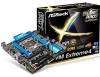
ASRock X99M Extreme4 Quick Installation Guide
ASRock X99M Extreme4 Manual
 |
View all ASRock X99M Extreme4 manuals
Add to My Manuals
Save this manual to your list of manuals |
ASRock X99M Extreme4 manual content summary:
- ASRock X99M Extreme4 | Quick Installation Guide - Page 1
change without notice, and should not be constructed as a commitment by ASRock. ASRock assumes no responsibility for any errors or omissions that may appear in CALIFORNIA, USA ONLY he Lithium battery adopted on this motherboard contains Perchlorate, a toxic substance controlled in Perchlorate Best - ASRock X99M Extreme4 | Quick Installation Guide - Page 2
Manufactured under license under U.S. Patent Nos: 5,956,674; 5,974,380; 6,487,535; 7,003,467 & other U.S. and worldwide patents issued & pending. DTS, the Symbol, & DTS and the Symbol together is a registered trademark & DTS Connect, DTS Interactive, DTS Neo:PC are trademarks of DTS, Inc. Product - ASRock X99M Extreme4 | Quick Installation Guide - Page 3
S_SATA3_0_1 BIOS_A_LED CMOS LAN PWR_FAN1 Battery 128Mb BIOS 128Mb BIOS BIOS_SEL1 A 1 SATA_PWR_1 B LAN BIOS_A BIOS_B BIOS_B_LED PCIE1 RoHS S_SATA3_2_3 M2_1 SATA3_0_3 CT5 Purity SoundTM 2 Ultra M.2 CT4 CT3 CT2 CT1 PCIe Gen3 x4 PCIE2 X99M Extreme4 Intel X99 SATA3_1_4 - ASRock X99M Extreme4 | Quick Installation Guide - Page 4
5 CPU Fan Connector (CPU_FAN2) 6 TPM Header (TPMS1) 7 ATX Power Connector (ATXPWR1) 8 USB 3.0 Header (USB3_5_6) 9 Chassis (PLED1) 17 System Panel Header (PANEL1) 18 Clear CMOS Jumper (CLRCMOS1) 19 Chassis Speaker Header (SPEAKER1) BIOS Selection Switch (BIOS_SEL1) 28 Power Fan Connector (PWR_FAN1) 2 - ASRock X99M Extreme4 | Quick Installation Guide - Page 5
I/O Panel 1 X99M Extreme4 46 2 3 57 15 14 13 12 11 10 98 No. Description No. Description 1 USB 2.0 Ports (USB12) 9 Optical SPDIF Out Port 2 LAN RJ-45 Port (Intel® I218V)* 10 USB 3.0 Ports (USB3_34) 3 LAN RJ-45 Port (Qualcomm® Atheros® AR8171)* 11 USB 3.0 Ports (USB3_12) 4 - ASRock X99M Extreme4 | Quick Installation Guide - Page 6
use the Rear Speaker, Central/Bass, and Front Speaker, or select "Realtek HDA Audio 2nd output" to use the front panel audio. *** he eSATA connector supports SATA with cables within 1 meters. he S_SATA3_3 connector is shared with the eSATA port. English 4 - ASRock X99M Extreme4 | Quick Installation Guide - Page 7
ind the latest VGA cards and CPU support list on ASRock's website as well. ASRock website http://www.asrock.com. 1.1 Package Contents • ASRock X99M Extreme4 Motherboard (Micro ATX Form Factor) • ASRock X99M Extreme4 Quick Installation Guide • ASRock X99M Extreme4 Support CD • 1 x I/O Panel Shield - ASRock X99M Extreme4 | Quick Installation Guide - Page 8
• Micro ATX Form Factor • High Density Glass Fabric PCB CPU • Supports Intel® CoreTM i7 and Xeon® 18-Core Processors Family for the LGA 2011-3 Socket • Digi Power design • 12 Power Phase design • Supports Intel® Turbo Boost 2.0 Technology • Supports Untied Overclocking Technology Chipset • Intel - ASRock X99M Extreme4 | Quick Installation Guide - Page 9
Out Port • 1 x eSATA Connector • 4 x USB 2.0 Ports (Supports ESD Protection (ASRock Full Spike Protection)) • 4 x USB 3.0 Ports (Supports ESD Protection (ASRock Full Spike Protection)) • 2 x RJ-45 LAN Ports with LED (ACT/LINK LED and SPEED LED) • 1 x Clear CMOS Switch • HD Audio Jacks: Rear Speaker - ASRock X99M Extreme4 | Quick Installation Guide - Page 10
SATA3 6.0 Gb/s Connectors, support RAID (RAID 0, RAID 1, RAID 5, RAID 10 and Intel Rapid Storage 13), NCQ, AHCI, Hot Plug and ASRock HDD Saver Technology (S_SATA3_3 connector is shared with the eSATA port) (S_SATA3_2 connector is shared with Ultra M.2 Socket) * RAID is supported on SATA3_0 ~ SATA3_5 - ASRock X99M Extreme4 | Quick Installation Guide - Page 11
X99M Extreme4 Hardware Monitor OS Certiications • CPU/Chassis temperature asrock.com Please realize that there is a certain risk involved with overclocking, including adjusting the setting in the BIOS, applying Untied Overclocking Technology, or using third-party overclocking tools. Overclocking - ASRock X99M Extreme4 | Quick Installation Guide - Page 12
Installation his is a Micro ATX form factor motherboard. Before you install the motherboard, study the coniguration of your chassis to ensure that the motherboard its into it. Pre-installation Precautions Take note of the following precautions before you install motherboard components or change any - ASRock X99M Extreme4 | Quick Installation Guide - Page 13
X99M Extreme4 2.1 Installing the CPU 1. Before you insert the 2011-3-Pin CPU into the socket, please check before installing the CPU. CAUTION: Please note that X99 platform is only compatible with the LGA 2011-3 socket, which is incompatible with the LGA 2011 socket (for X79 platform). 1 A B A - ASRock X99M Extreme4 | Quick Installation Guide - Page 14
A 3 B 4 5 12 English - ASRock X99M Extreme4 | Quick Installation Guide - Page 15
6 7 A B 8 X99M Extreme4 A B English Please save and replace the cover if the processor is removed. he cover must be placed if you wish to return the motherboard for ater service. 13 - ASRock X99M Extreme4 | Quick Installation Guide - Page 16
2.2 Installing the CPU Fan and Heatsink 1 2 CPU_FAN English 14 - ASRock X99M Extreme4 | Quick Installation Guide - Page 17
X99M Extreme4 2.3 Installation of Memory Modules (DIMM) his motherboard provides four 284-pin DDR4 (Double Data Rate 4) DIMM slots, and supports Quad Channel Memory Technology. 1. For quad channel coniguration, you always need to install identical (the same brand, speed, size and chip-type) DDR4 - ASRock X99M Extreme4 | Quick Installation Guide - Page 18
1 2 3 16 English - ASRock X99M Extreme4 | Quick Installation Guide - Page 19
X99M Extreme4 2.4 Expansion Slots (PCI Express Slots) here are 3 PCI Express slots on the motherboard. Before installing an expansion card, better thermal environment, please connect a chassis fan to the motherboard's chassis fan connector (CHA_FAN1 or CHA_FAN2) when using multiple graphics cards. - ASRock X99M Extreme4 | Quick Installation Guide - Page 20
on CLRCMOS1 for 5 seconds. However, please do not clear the CMOS right ater you update the BIOS. If you need to clear the CMOS when you just inish updating the BIOS, you must boot up the system irst, and then shut it down before you do the clear-CMOS action. Please be noted that the password, date - ASRock X99M Extreme4 | Quick Installation Guide - Page 21
X99M Extreme4 2.6 Onboard Headers and Connectors Onboard headers and connectors are NOT jumpers. Do NOT place jumper caps over these headers and connectors. Placing jumper caps over the headers and connectors will cause permanent damage to the motherboard. System Panel Header (9-pin PANEL1) (see - ASRock X99M Extreme4 | Quick Installation Guide - Page 22
Ultra M.2 Socket has been occupied, the internal S_SATA3_2 will not function. * RAID is supported on SATA3_0 ~ SATA3_5 ports only. SATA3_5 SATA3_4 SATA3_2 SATA3_1 USB 2.0 Headers are two headers on this motherboard. Each USB 2.0 header can support two ports. Vbus IntA_PA_SSRXIntA_PA_SSRX+ GND - ASRock X99M Extreme4 | Quick Installation Guide - Page 23
for connecting audio devices to the front audio panel. 1. High Deinition Audio supports Jack Sensing, but the panel wire on the chassis must support HDA to function correctly. Please follow the instructions in our manual and chassis manual to install your system. 2. If you use an AC'97 audio panel - ASRock X99M Extreme4 | Quick Installation Guide - Page 24
12 24 1 13 8 5 4 1 GND +12V DETECT 1 his motherboard provides a 24-pin ATX power connector. To use a 20-pin ATX power supply, please plug it along Pin 1 and Pin 13. his motherboard provides an 8-pin ATX 12V power connector. To use a 4-pin ATX power supply, please plug it along Pin 1 and Pin - ASRock X99M Extreme4 | Quick Installation Guide - Page 25
) (see p.1, No. 23) TPM Header (17-pin TPMS1) (see p.1, No. 6) X99M Extreme4 RRXD1 DDTR#1 DDSR#1 CCTS#1 1 RRI#1 RRTS#1 GND TTXD1 DDCD#1 his COM1 header supports a serial port module. PCIRST# FRAME PCICLK his connector supports Trusted Platform Module (TPM) system, which can securely store keys - ASRock X99M Extreme4 | Quick Installation Guide - Page 26
2.7 Smart Switches he motherboard has two smart switches: one Clear CMOS Switch and one BIOS Selection Switch, allowing users to clear the CMOS values or boot from diferent BIOS. Clear CMOS Switch (CLRCBTN) (see p.3, No. 14) Clear CMOS Switch allows users to quickly clear the CMOS values. his - ASRock X99M Extreme4 | Quick Installation Guide - Page 27
X99M Extreme4 2.8 Dr. Debug Dr. Debug is used to provide code information, which makes troubleshooting even easier. Please see the diagrams below for reading the Dr. Debug codes. Code Description 00 Please check if the CPU is installed correctly and then clear CMOS. 0d Problem related to - ASRock X99M Extreme4 | Quick Installation Guide - Page 28
, please install only one memory module or try using other memory modules. d6 he VGA could not be recognized. Please clear CMOS and try re-installing the VGA card. If the problem still exists, please try installing the VGA card in other slots or use other VGA cards. d7 he Keyboard and mouse - ASRock X99M Extreme4 | Quick Installation Guide - Page 29
X99M Extreme4 2.9 M.2_SSD (NGFF) Module Installation Guide he M.2, also known as the Next Generation Form Factor (NGFF), is a small size and versatile card edge connector that aims to replace mPCIe and mSATA. - ASRock X99M Extreme4 | Quick Installation Guide - Page 30
hand. Step 4 Peel of the yellow protective ilm on the nut to be used. Hand tighten the standof into the desired nut location on the motherboard. Step 5 Align and gently insert the M.2 (NGFF) SSD module into the M.2 slot. Please be aware that the M.2 (NGFF) SSD module only its in one orientation - ASRock X99M Extreme4 | Quick Installation Guide - Page 31
X99M Extreme4 M.2_SSD (NGFF) Module Support List PCIe Interface SATA Interface Plextor PX-AG256M6e Plextor PX-AG512M6e Intel SSDSCKGW080A401/80G Kingston RBU-SNS8400S3/180GD For the latest updates of M.2_SSD (NFGG) module support list, please visit our website for details: http://www.asrock.com - ASRock X99M Extreme4 | Quick Installation Guide - Page 32
2.10 HDD Saver Cable Installation Guide The HDD Saver Connector on this motherboard allows you to switch on and off your SATA HDD(s). * he HDD Saver Connector supports up to two SATA HDDs. 2. Connect one end of the SATA data cable to a SATA port on the motherboard. hen connect the other end to your - ASRock X99M Extreme4 | Quick Installation Guide - Page 33
auf der ASRock-Webseite: ASRock-Website http://www.asrock.com. 1.1 Lieferumfang • ASRock X99M Extreme4 - Motherboard (Micro-ATX-Formfaktor) • ASRock X99M Extreme4 - Schnellinstallationsanleitung • ASRock X99M Extreme4 - Support-CD • 1 x E/A-Blendenabschirmung • 1 x ASRock SLI_Bridge-Karte - ASRock X99M Extreme4 | Quick Installation Guide - Page 34
1.2 Technische Daten Plattform • Micro-ATX-Formfaktor • Leiterplatte mit hochdichtem Glasgewebe Prozessor • Unterstützt Intel® CoreTM i7- und Xeon®-18-Kern- Prozessorenfamilie für LGA 2011-3-Socket • Digipower-Design • 12-Leistungsphasendesign • Unterstützt Intel® Turbo Boost 2.0-Technologie • - ASRock X99M Extreme4 | Quick Installation Guide - Page 35
X99M Extreme4 Audio LAN Rückblende, E/A • 7.1-Kanal-HD-Audio mit Inhaltsschutz (Realtek ALC1150Audiocodec) • Erstklassige Blu-ray-Audiounterstützung • Unterstützt Überspannungsschutz (ASRock PCB-isolierte Abschirmung • Unterstützt DTS Connect • 1 x Intel® I218V (Gigabit LAN PHY 10/100/1000 Mb/s) • - ASRock X99M Extreme4 | Quick Installation Guide - Page 36
tzt RAID (RAID 0, RAID 1, RAID 5, RAID 10, Intel Rapid Storage Technology 13), NCQ, AHCI, Hot-Plugging und ASRock HDD BIOS-Auswahlschalter Deutsch BIOSFunktion • 2 x 128-Mb-AMI-UEFI-Legal-BIOS mit Unterstützung me- hrsprachiger graischer Benutzerschnittstellen (1 x Haupt- BIOS und 1 x Ausfall-BIOS - ASRock X99M Extreme4 | Quick Installation Guide - Page 37
X99M Extreme4 Hardwareüberwachung Betriebssystem Zertiizierungen • CPU-/Gehäusetemperaturerkennung • CPU/Gehäuse/Netzteil-Lü http://www.asrock.com Bitte beachten Sie, dass mit einer Übertaktung, zu der die Anpassung von BIOSEinstellungen, die Anwendung der Untied Overclocking Technology oder - ASRock X99M Extreme4 | Quick Installation Guide - Page 38
dann Kontakt 2 und Kontakt 3 an CLRCMOS1 5 Sekunden lang mit einer Jumper-Kappe kurz. Löschen Sie den CMOS jedoch nicht direkt nach der BIOS-Aktualisierung. Falls Sie den CMOS direkt nach Abschluss der BIOS-Aktualisierung löschen müssen, starten Sie das System zunächst; fahren Sie es dann vor der - ASRock X99M Extreme4 | Quick Installation Guide - Page 39
X99M Extreme4 1.4 Integrierte Stiftleisten und Anschlüsse Integrierte Stitleisten und Anschlüsse sind KEINE Jumper. Bringen Sie KEINE Jumper-Kappen an diesen Stitleisten und Anschlüssen an. Durch Anbringen von Jumper-Kappen an diesen Stitleisten und Anschlüssen können Sie das Motherboard dauerhat - ASRock X99M Extreme4 | Quick Installation Guide - Page 40
ckung des Ultra M.2-Sockels ist der interne S_SATA3_2-Port ohne Funktion. * RAID wird nur an den Ports SATA3_0 bis SATA3_5 unterstützt. SATA3_5 SATA3_4 2.0-Ports an der E/A-Blende beinden sich zwei Stitleisten an diesem Motherboard. Jede USB 2.0-Stitleiste kann zwei Ports unterstützen. Deutsch 38 - ASRock X99M Extreme4 | Quick Installation Guide - Page 41
X99M Extreme4 USB 3.0-Stitleisten (19-polig, USB3_5_6) (siehe S. 1, Nr. 8) Vbus IntA_PA_SSRXIntA_PA_SSRX+ GND Neben vier USB 3.0-Ports an der E/A-Blende beindet sich eine Stitleiste an diesem Motherboard. Jede USB 3.0-Stitleiste kann zwei Ports unterstützen. Audiostitleiste (Frontblende) (9- - ASRock X99M Extreme4 | Quick Installation Guide - Page 42
schließen Sie es zur Nutzung eines 20-poligen ATX-Netzteils entlang Kontakt 1 und Kontakt 13 an. 8 5 Dieses Motherboard bietet einen 8-poligen ATX-12-V-Netzanschluss. 4 1 Bitte schließen Sie es zur Nutzung eines 4-poligen ATX-Netzteils entlang Kontakt 1 und Kontakt 5 an. GND +12V DETECT - ASRock X99M Extreme4 | Quick Installation Guide - Page 43
X99M Extreme4 hunderboltErweiterungskartenanschluss (5-polig, TBT1) (siehe S. 1, Nr. 24) Serieller-Port-Stitleiste (9-polig, COM1) (siehe S. 1, Nr. 23) TPM-Stitleiste (17-polig, TPMS1) (siehe S. 1, Nr. 6) Bitte verbinden Sie ein - ASRock X99M Extreme4 | Quick Installation Guide - Page 44
Schalter Das Motherboard hat zwei intelligente Schalter: Ein CMOS-löschen-Schalter und ein BIOS-Auswahlschalter, wodurch Benutzer die CMOS-Werte löschen oder von einem anderen BIOS starten können. CMOS-löschen-Schalter (CLRCBTN) (siehe Seite 3, Nr. 14) Mit dem CMOS-löschenSchalter können - ASRock X99M Extreme4 | Quick Installation Guide - Page 45
sur le site Internet de ASRock. Site Internet ASRock http://www.asrock.com. 1.1 Contenu de l'emballage • Carte mère ASRock X99M Extreme4 (facteur de forme Micro ATX) • Guide d'installation rapide ASRock X99M Extreme4 • CD d'assistance ASRock X99M Extreme4 • 1 x panneau de protection E/S • 1 x carte - ASRock X99M Extreme4 | Quick Installation Guide - Page 46
® CoreTM i7 et Xeon® pour le socket LGA 2011-3 • Conception Digi Power • Alimentation à 12 phases • Prend en charge la technologie Intel® Turbo Boost 2.0 • Prend en charge la technologie Untied Overclocking Chipset • Intel® X99 Mémoire • Technologie de mémoire quadri-canal DDR4 • 4 x fentes DIMM - ASRock X99M Extreme4 | Quick Installation Guide - Page 47
)) • 4 x ports USB 3.0 (Protection contre les décharges électrostatiques (Protection complète contre les pics ASRock)) • 2 x ports RJ-45 LAN avec LED (LED ACT/LIEN et LED VITESSE) • 1 x bouton Clear CMOS • Connecteurs jack audio HD : Haut-parleur arrière / central / basses / entrée ligne / haut - ASRock X99M Extreme4 | Quick Installation Guide - Page 48
RAID (RAID 0, RAID 1, RAID 5, RAID 10, technologies Intel Rapid Storage 13), NCQ, AHCI, « Hot Plug » et sauvegarde HDD ASRock • 1 x connecteur d'alimentation ATX 24 broches • 1 x connecteur ASRock)) • 1 x Dr Debug avec témoin LED • 1 x bouton de sélection du BIOS Caractéristiques du BIOS • 2 x BIOS - ASRock X99M Extreme4 | Quick Installation Guide - Page 49
X99M Extreme4 Surveillance du matériel Système d'exploitation Certiications • Ré asrock.com Il est important de signaler que l'overcloking présente certains risques, incluant des modiications du BIOS, l'application d'une technologie d'overclocking déliée et l'utilisation d'outils d'overclocking - ASRock X99M Extreme4 | Quick Installation Guide - Page 50
jour du BIOS, vous devez tout d'abord redémarrer le système, puis l'éteindre avant de procéder à l'efacement de la CMOS. Veuillez noter que les paramètres mot de passe, date, heure et proil de l'utilisateur seront uniquement efacés en cas de retrait de la pile de la CMOS. Le bouton Clear CMOS poss - ASRock X99M Extreme4 | Quick Installation Guide - Page 51
X99M Extreme4 1.4 Embases et connecteurs de la carte mère Les embases et connecteurs situés sur la carte NE SONT PAS des cavaliers. Ne placez JAMAIS de capuchons - ASRock X99M Extreme4 | Quick Installation Guide - Page 52
arrière a été connecté, le S_SATA3_3 interne ne fonctionnera pas. Si le socket Ultra M.2 est occupé, le S_SATA3_2 interne ne fonctionnera pas. * RAID est uniquement pris en charge sur les ports SATA3_0 ~ SATA3_5. SATA3_5 SATA3_4 SATA3_2 SATA3_1 Français Embases USB 2.0 (USB5_6 à 9 broches) (voir - ASRock X99M Extreme4 | Quick Installation Guide - Page 53
X99M Extreme4 Embase tre compatible avec la HDA pour fonctionner correctement. Veuillez suivre les instructions igurant dans notre manuel et dans le manuel du châssis les brancher avec le panneau audio AC'97. E. Pour activer le micro frontal, sélectionnez l'onglet « FrontMic » du panneau de contrôle - ASRock X99M Extreme4 | Quick Installation Guide - Page 54
broches) (voir p.1, No. 11) 12 24 1 13 8 5 4 1 GND +12V DETECT 1 Cette carte mère est dotée d'un connecteur d'alimentation ATX à 24 broches. Pour utiliser une alimentation ATX à 20 broches, veuillez efectuer les branchements sur la Broche 1 et la Broche 13. Cette carte mère est dotée d'un - ASRock X99M Extreme4 | Quick Installation Guide - Page 55
X99M Extreme4 Connecteur hunderbolt AIC (TBT1 à 5 broches) (voir p.1, No. 24) Embase pour port série (COM1 à 9 broches) (voir p.1, No. 23) Embase TPM (TPMS1 à 17 broches) (voir p.1, No. 6) Veuillez - ASRock X99M Extreme4 | Quick Installation Guide - Page 56
mère est équipée de deux boutons intelligents : bouton d'efacement CMOS et bouton de sélecteur de BIOS qui permettent aux utilisateurs d'efacer les valeurs CMOS en toute simplicité ou de démarrer depuis un BIOS diférent. Bouton d'efacement CMOS (CLRCBTN) (voir p.3, No. 14) Le bouton d'efacement - ASRock X99M Extreme4 | Quick Installation Guide - Page 57
anche sul sito Web di ASRock. Sito Web di ASRock http://www.asrock.com. 1.1 Contenuto della confezione • Scheda madre ASRock X99M Extreme4 (Form Factor Micro ATX) • Guida all'installazione rapida di ASRock X99M Extreme4 • CD di supporto di ASRock X99M Extreme4 • 1 x mascherina metallica posteriore - ASRock X99M Extreme4 | Quick Installation Guide - Page 58
di forma Micro ATX • PBC di ibra di vetro ad alta densità CPU • Supporta la famiglia di processori Intel® CoreTM i7 e Xeon® 18-Core per il socket LGA 2011-3 • Design Digi Power • Potenza a 12 fasi • Supporta la tecnologia Intel® Turbo Boost 2.0 • Supporta la tecnologia overclocking "slegata - ASRock X99M Extreme4 | Quick Installation Guide - Page 59
X99M Extreme4 Audio LAN I/O pannello posteriore • Audio HD a 7.1 canali con Content Protection (codec audio Realtek ALC1150) • Supporto audio Blu-ray Premium • Supporto protezione da sovratensione (protezione completa ASRock PCB • Supporta DTS Connect • 1 x Intel® I218V (Gigabit LAN PHY 10/100/1000 - ASRock X99M Extreme4 | Quick Installation Guide - Page 60
RAID (RAID 0, RAID 1, RAID 5, RAID 10, Intel Rapid Storage Technology 13), NCQ, AHCI, Hot Plug e tecnologia ASRock pin) • 1 x Connettore alimentazione ATX 24 pin • 1 x Connettore BIOS Funzione BIOS • BIOS legale 2 x 128Mb AMI UEFI con supporto GUI multi- lingue (1 x Main BIOS e 1 x Backup BIOS - ASRock X99M Extreme4 | Quick Installation Guide - Page 61
X99M Extreme4 Hardware asrock.com Prestare attenzione al potenziale rischio previsto nella pratica di overclocking, inclusa la regolazione delle impostazioni nel BIOS, l'applicazione di tecnologia di Untied Overclocking o l'utilizzo di strumenti di overclocking di terze parti. L'overclocking - ASRock X99M Extreme4 | Quick Installation Guide - Page 62
jumper per cortocircuitare il pin2 e il pin3 su CLRCMOS1 per 5 secondi. Tuttavia, non azzerare la CMOS subito dopo aver aggiornato il BIOS. Se è necessario azzerare la CMOS dopo l'aggiornamento del BIOS, è necessario riavviare prima il sistema e in seguito spegnerlo prima di eseguire l'operazione di - ASRock X99M Extreme4 | Quick Installation Guide - Page 63
X99M Extreme4 1.4 Header e connettori sulla scheda Gli header e i connettori sulla scheda NON sono jumper. NON posizionare cappucci del jumper su questi header e connettori. Il posizionamento di cappucci - ASRock X99M Extreme4 | Quick Installation Guide - Page 64
posteriore I/O è collegata, il connettore S_SATA3_3 interno non funzionerà. Se il socket Ultra M.2 è occupato, il S_SATA3_2 interno non funzionerà. * RAID è supportato solo su porte SATA3_0 ~ SATA3_5. SATA3_5 SATA3_4 SATA3_2 SATA3_1 Italiano Header USB 2.0 (USB5_6 a 9 pin) (vedere pag. 1, n. 22 - ASRock X99M Extreme4 | Quick Installation Guide - Page 65
X99M Extreme4 Header audio pannello anteriore (AUDIO1_HD a 9 pin) (vedere pag. 1, n. 26) GND PRESENCE deve supportare HDA per funzionare correttamente. Seguire le istruzioni presenti nel nostro manuale e nel manuale dello chassis per installare il sistema. 2. Se si utilizza un pannello audio - ASRock X99M Extreme4 | Quick Installation Guide - Page 66
di collegare una ventola della CPU a 3 pin, collegarla al pin 1-3. Questa scheda madre è dotata di un connettore di alimentazione ATX a 24 pin. Per utilizzare un'alimentazione ATX a 20 pin, collegarla lungo il pin1 e il pin 13. 8 5 Questa scheda madre è dotata di un connettore di alimentazione - ASRock X99M Extreme4 | Quick Installation Guide - Page 67
X99M Extreme4 Header porta seriale (COM1 a 9 pin) (vedere pag. 1, n. 23) Header TPM (TPMS1 a 17 pin) (vedere pag. 1, n. 6) RRXD1 DDTR#1 DDSR#1 CCTS#1 1 RRI#1 RRTS#1 GND TTXD1 DDCD#1 Questo - ASRock X99M Extreme4 | Quick Installation Guide - Page 68
di uno interruttori intuitivi: Interruttore Clear CMOS ed un interruttore di selezione BIOS che consentono di cancellare i valori CMOS oppure eseguire l'avvio su un BIOS diverso. Interruttore Clear CMOS (CLRCBTN) (vedere pag. 3, n. 14) L'interruttore Clear CMOS consente di cancellare rapidamente - ASRock X99M Extreme4 | Quick Installation Guide - Page 69
web de ASRock. Sitio web de ASRock http://www.asrock.com. 1.1 Contenido del paquete • Placa base ASRock X99M Extreme4 (Factor de forma Micro ATX) • Guía de instalación rápida de ASRock X99M Extreme4 • CD de soporte de ASRock X99M Extreme4 • 1 escudo panel I/O • 1 tarjeta ASRock SLI_Bridge • 2 cables - ASRock X99M Extreme4 | Quick Installation Guide - Page 70
• Factor de forma Micro ATX • PCB de ibra de vidrio de alta densidad CPU • Admite la familia de procesadores Intel® CoreTM i7 y Xeon® 18-Core para el zócalo LGA 2011-3 • Diseño Digi Power • Diseño de 12 fases de alimentación • Compatible con la tecnología de Intel® Turbo Boost 2.0 • Admite - ASRock X99M Extreme4 | Quick Installation Guide - Page 71
X99M Extreme4 Audio LAN Panel trasero I/O • 7.1 Audio CH HD con Protección de contenido (Realtek ALC1150 Audio Codec) • Compatible con audio Blu-ray Premium • Compatible con protección por sobretensión (protección ASRock • Compatible con DTS Connect • 1 x Intel® I218V (Gigabit LAN PHY 10/100/1000 - ASRock X99M Extreme4 | Quick Installation Guide - Page 72
BIOS • 10 conectores SATA3 de 6,0 Gb/s, compatibilidad con RAID (RAID 0, RAID 1, RAID 5, RAID 10, Intel Rapid Storage Technology 13), NCQ, AHCI y conexión en caliente y tecnología de ahorro ASRock ón (de 3 pines) • 1 Conector de alimentación ATX de 24 pines • 1 Conector de alimentación de 8 - ASRock X99M Extreme4 | Quick Installation Guide - Page 73
X99M Extreme4 Monitor del hardware SO Certiicaciones • Multiajuste de voltaje de CPU, DRAM, PCH 1,05V, : http://www.asrock.com Tenga en cuenta que existen ciertos riesgos relacionados con el overclocking (sobreaceleración), incluyendo el ajuste de la coniguración del BIOS, aplicando la Tecnolog - ASRock X99M Extreme4 | Quick Installation Guide - Page 74
el pin2 y el pin3 en el CLRCMOS1 durante 5 segundos. Sin embargo, no borre el CMOS justo después de que haya actualizado el BIOS. Si necesita borrar el CMOS cuando acabe de actualizar el BIOS, deberá arrancar el sistema primero y, a continuación, deberá apagarlo antes de que realice el borrado - ASRock X99M Extreme4 | Quick Installation Guide - Page 75
X99M Extreme4 1.4 Conectores y cabezales incorporados Los cabezales y conectores incorporados NO son puentes. NO coloque tapas de puente sobre estos cabezales y conectores. Si coloca tapas de puente sobre - ASRock X99M Extreme4 | Quick Installation Guide - Page 76
en el panel trasero I/O, no funcionará el puerto interno S_SATA3_3. Si se ha ocupado el módulo Ultra M.2, el S_SATA3_2 interno no funcionará. * RAID solamente se admite en los puertos SATA3_0 ~ SATA3_5. SATA3_5 SATA3_4 SATA3_2 SATA3_1 Español Cabezales USB 2.0 (USB5_6 de 9 pines) (consulte la - ASRock X99M Extreme4 | Quick Installation Guide - Page 77
X99M Extreme4 Cabezal de audio del panel frontal (HD_AUDIO1 de 9 pines) (consulte la compatible con HDA para que pueda funcionar correctamente. Siga las instrucciones que se indican en nuestro manual y en el manual del chasis para instalar su sistema. 2. Si utiliza un panel de audio AC'97, col - ASRock X99M Extreme4 | Quick Installation Guide - Page 78
un ventilador de CPU de 3 pines, conéctelo al Pin 1-3. 12 24 1 13 Esta placa base contiene un conector de alimentación ATX de 24 pines. Para utilizar una toma de alimentación ATX de 20 pines, conéctela en los Pines del 1 al 13. 8 5 Esta placa base contiene un conector de aliment- aci - ASRock X99M Extreme4 | Quick Installation Guide - Page 79
X99M Extreme4 Cabezal de puerto serie (COM1 de 9 pines) (consulte la pág.1, N.º 23) Cabezal TPM (TPMS1 de 17 pines) (consulte la pág.1, N.º 6) RRXD1 DDTR#1 DDSR#1 CCTS#1 1 RRI#1 RRTS#1 GND - ASRock X99M Extreme4 | Quick Installation Guide - Page 80
contiene dos interruptores inteligentes: Interruptor de borrado de CMOS y un interruptor de selección BIOS, que permiten a los usuarios borrar los valores de CMOS, o arrancar desde un BIOS diferente. Interruptor de borrado de CMOS (CLRCBTN) (consulte la pág. 3, N.º 14) El interruptor de borrado - ASRock X99M Extreme4 | Quick Installation Guide - Page 81
X99M Extreme4 1 ASRock X99M Extreme4 ASRock ASRock BIOS ASRock ASRock VGA ASRock http://www.asrock.com. 1.1 ASRock X99M Extreme4 Micro ATX ASRock X99M Extreme4 ASRock X99M Extreme4 • 1 1 x карты ASRock SLI_Bridge • 2 Serial ATA (SATA 1 x HDD Saver • 1 x Ultra M.2 79 - ASRock X99M Extreme4 | Quick Installation Guide - Page 82
Overclocking Чипсет • Intel® X99 Память Quad Channel DDR4 Memory Technology • 4 DDR4 DIMM DDR4 3000+(OC)*/2933+ (OC)/2800(OC)/2400(OC)/ 2133/1866/ 1600/1333/1066 Non-ECC Unbufered Memory Support List ASRock. (http://www.asrock.com RDIMM DIMM DDR4 ECC RDIMM Intel® Xeon E5 в LGA 2011 - ASRock X99M Extreme4 | Quick Installation Guide - Page 83
X99M Extreme4 Аудио ЛВС • 7.1 HD Audio Realtek ALC1150) Premium Blu-ray Audio ASRock Full Spike Protection Purity Sound™ 2 Nichicon Fine Gold - 115 дБ SNR DAC TI® NE5532 Premium Headset Ampliier 600 Direct Drive DTS • 1 x Intel® I218V (Gigabit LAN PHY 10/100/1000 1 x Qualcomm® - ASRock X99M Extreme4 | Quick Installation Guide - Page 84
• 10 x SATA3 6,0 RAID (RAID 0, RAID 1, RAID 5, RAID 10, Intel Rapid Storage Technology 13), NCQ, AHCI ASRock HDD Saver S_SATA3_3 eSATA S_SATA3_2 Ultra M.2 Socket) RAID SATA3_0 ~ SATA3_5. • 1 x eSATA NCQ, AHCI и 1 x Ultra M.2 Socket M.2 SATA3 6,0 M.2 PCI Express Gen3 x4 (32 ГБ - ASRock X99M Extreme4 | Quick Installation Guide - Page 85
X99M Extreme4 12V, +5V, +3,3V ОС • Microsot® Windows® 8.1 32-bit / 8.1 64-bit / 8 32-bit / 8 64-bit / 7 32-bit / 7 64-bit • FCC, CE, WHQL ErP/EuP ErP/EuP) http://www.asrock.com BIOS Untied Overclocking Technology 32 Windows 4 64 Windows Windows ASRock XFast - ASRock X99M Extreme4 | Quick Installation Guide - Page 86
1.3 3 1 и 2 CMOS (CLRCMOS1 1, № 18) CMOS CLRCMOS1 CMOS 15 2 и 3 на CLRCMOS1 на 5 CMOS BIOS CMOS BIOS CMOS CMOS. CMOS CMOS. 84 - ASRock X99M Extreme4 | Quick Installation Guide - Page 87
X99M Extreme4 1.4 9 PANEL1 1, № 17) PLED+ PLEDPWRBTN# GND 1 GND RESET# GND HDLEDHDLED+ PWRBTN RESET PLED S1/S3 S4 S5 HDLED 85 - ASRock X99M Extreme4 | Quick Installation Guide - Page 88
№ 15) SATA3_0 S_SATA3_2 S_SATA3_0 1 PLEDPLED+ PLED+ SATA3_3 S_SATA3_3 S_SATA3_1 SATA3 SATA 6,0 eSATA S_SATA3_3 Ultra M.2 Socket S_SATA3_2 RAID SATA3_0 ~ SATA3_5. SATA3_5 SATA3_4 SATA3_2 SATA3_1 USB 2.0. (9 USB5_6 1, № 22) (9 USB7_8 1, № 21) USB_PWR PP+ GND DUMMY 1 GND - ASRock X99M Extreme4 | Quick Installation Guide - Page 89
X99M Extreme4 9 HD_ AUDIO1 1, № 26) GND PRESENCE# MIC_RET OUT_RET 1 OUT2_L J_SENSE OUT2_R MIC2_R MIC2_L 1 HDA 2 AC'97 A Mic_IN (MIC) к MIC2_L. B Audio_R (RIN) к OUT2_R, Audio_L (LIN) к OUT2_L. C GND - ASRock X99M Extreme4 | Quick Installation Guide - Page 90
PCIe (4 PCIE_ PWR1 1, № 25) HDD Saver (4 SATA_ PWR_1 1, № 11) 4 3 21 CPU_FAN_SPEED FAN_SPEED_CONTROL GND FAN_VOLTAGE FAN_SPEED 4 3 1-3. 12 24 1 13 24 20 ATX 1 13. 8 5 8 4 1 12 4 ATX, 1 5. GND +12V DETECT 1 4 Molex. HDD Saver. 88 - ASRock X99M Extreme4 | Quick Installation Guide - Page 91
X99M Extreme4 hunderbolt AIC (5 TBT1 1, № 24) AIC hunderbolt 5 GPIO). 9 COM1 1, № 23) RRXD1 DDTR#1 DDSR#1 CCTS#1 1 RRI#1 RRTS#1 GND TTXD1 DDCD#1 17 TPMS1 1, № 6) PCIRST# FRAME PCICLK Trusted Platform Module (TPM 89 - ASRock X99M Extreme4 | Quick Installation Guide - Page 92
1.5 BIOS BIOS. CMOS (CLRCBTN 3, № 14) CMOS CMOS. BIOS (BIOS_SEL1 1, № 27) AB BIOS BIOS A или BIOS B. BIOS BIOS (BIOS_A) и BIOS BIOS_B BIOS BIOS BIOS BIOS UEFI Secure Backup UEFI BIOS BIOS BIOS BIOS BIOS (BIOS_A_LED или BIOS_B_LED). 90 - ASRock X99M Extreme4 | Quick Installation Guide - Page 93
no site da ASRock. Site da ASRock http://www.asrock.com. 1.1 Conteúdo da embalagem • Placa Mãe ASRock X99M Extreme4 (Fator de Forma Micro ATX) • Guia de Instalação Rápida da ASRock X99M Extreme4 • CD de Suporte da ASRock X99M Extreme4 • 1 x Painel de E/S • 1 x Placa ASRock SLI_Bridge • 2 x Cabos de - ASRock X99M Extreme4 | Quick Installation Guide - Page 94
Micro ATX • Tecido de Vidro de Alta densidade PCB CPU • Suporta Família de Processadores Intel® CoreTM i7 e Xeon® 18- Core para o Soquete LGA 2011-3 • Design Digi Power • Design com 12 fases de alimentação • Suporta a tecnologia Intel® Turbo Boost 2.0 • Suporta a tecnologia Untied Overclocking - ASRock X99M Extreme4 | Quick Installation Guide - Page 95
X99M Extreme4 Português Áudio LAN E/S do painel posterior • Áudio HD de 7.1 canais com proteção de conteúdo (Codec de áudio Realtek ALC1150) • Suporte áudio Blu-ray superior • Suporta proteção contra sobretensão (Proteção Total Contra Picos ASRock DTS Connect • 1 x Intel® I218V (Gigabit LAN PHY - ASRock X99M Extreme4 | Quick Installation Guide - Page 96
Armazenamento • 10 x Conectores SATA3 6,0 Gb/s, suporte RAID (RAID 0, RAID 1, RAID 5, RAID 10, Tecnologia de Armazenamento Rápido Intel® 13), NCQ, AHCI e Conexão a Quente e Tecnologia Protetora de HDD ASRock (O conector S_SATA3_3 é compartilhada com a porta eSATA) (O conector S_SATA3_2 é - ASRock X99M Extreme4 | Quick Installation Guide - Page 97
X99M Extreme4 Monitor de hardware SO Certiicações • asrock.com Por favor, observe que existe um certo risco envolvendo overclocking, incluindo o ajuste das deinições na BIOS, a aplicação de tecnologia Untied Overclocking ou a utilização de ferramentas de overclocking de terceiros. O overclocking - ASRock X99M Extreme4 | Quick Installation Guide - Page 98
do jumper para ligar o pino2 e o pino3 no CLRCMOS1 durante 5 segundos. No entanto, não apague o CMOS logo após ter realizado a atualização da BIOS. Se você precisar apagar o CMOS logo após ter terminado uma atualização da BIOS, deverá primeiro iniciar o sistema e voltar a encerrá-lo antes de apagar - ASRock X99M Extreme4 | Quick Installation Guide - Page 99
X99M Extreme4 1.4 Suportes e conectores onboard Os conectores e suportes onboard NÃO são jumpers. NÃO coloque tampas de jumpers sobre estes terminais e conectores. Colocar tampas de jumpers sobre os terminais e conectores irá - ASRock X99M Extreme4 | Quick Installation Guide - Page 100
no painel posterior de E/S estiver ligada, a S_ SATA3_3 interna não irá funcionar. Se o soquete Ultra M.2 foi ocupado, o S_SATA3_2 não irá funcionar. * RAID é compatível apenas com as portas SATA3_0 ~ SATA3_5. SATA3_5 SATA3_4 SATA3_2 SATA3_1 Português Suportes USB 2.0 (USB5_6 de 9 pinos) (ver - ASRock X99M Extreme4 | Quick Installation Guide - Page 101
X99M Extreme4 Suporte de áudio do painel frontal (HD_AUDIO1 de 9 pinos) (ver p.1, N.º 26 painel no chassi deverá suportar HDA para funcionar corretamente. Por favor, siga as instruções no nosso manual e no manual do chassi para instalar o seu sistema. 2. Se utilizar um painel de áudio AC'97, instale - ASRock X99M Extreme4 | Quick Installation Guide - Page 102
de 20 pinos, introduza-a no Pino 1 e Pino 13. 8 5 Esta placa-mãe inclui um conector de alimentação de 12V ATX de 8 pinos. 4 1 Para utilizar uma fonte de alimentação ATX de 4 pinos, introduza-a no Pino 1 e Pino 5. GND +12V DETECT Por favor conecte um cabo de alimentação molex de 4 pinos - ASRock X99M Extreme4 | Quick Installation Guide - Page 103
X99M Extreme4 Suporte da porta serial (COM1 de 9 pinos) (ver p.1, N.º 23) Suporte TPM (TPMS1 de 17 pinos) (ver p.1, N.º 6) RRXD1 DDTR#1 DDSR#1 CCTS#1 1 RRI#1 RRTS#1 GND TTXD1 DDCD#1 - ASRock X99M Extreme4 | Quick Installation Guide - Page 104
, que permite aos usuários limpar os valores de CMOS ou inicializar de BIOS diferentes. Interruptor para apagar o CMOS (CLRCBTN) (veja p.3, No. 14) O interruptor para apagar o CMOS permite aos usuários apagar os valores CMOS rapidamente. Esta função pode ser utilizada apenas quando o computador - ASRock X99M Extreme4 | Quick Installation Guide - Page 105
ı ve CPU destek listelerini de ASRock'ın web sitesinden bulabilirsiniz. ASRock web sitesi http://www.asrock.com. 1.1 Ambalaj İçeriği • ASRock X99M Extreme4 Anakartı (Micro ATX Form Faktörü) • ASRock X99M Extreme4 Hızlı Kurulum Kılavuzu • ASRock X99M Extreme4 Destek CD'si • 1 x I/O Panel Kalkan - ASRock X99M Extreme4 | Quick Installation Guide - Page 106
Platform • Micro ATX Form Faktörü • Yüksek Yoğunluklu Cam Elyaf PCB CPU • LGA 2011-3 Soketi için Intel® CoreTM i7 ve Xeon® 18 Çekirdek İşlemci Ailesi Desteği • Dijital Güç tasarımı • 12 Güç Sahası tasarımı • Intel® Turbo Boost 2.0 Teknolojisini destekler • Untied Overclocking Teknolojisini - ASRock X99M Extreme4 | Quick Installation Guide - Page 107
X99M Extreme4 Ses LAN Arka Panel I/O • İçerik Koruma Özelliği ile 7.1 CH HD Ses (Realtek ALC1150 Ses Codec Bileşeni) • Üstün Blu-ray Ses desteği • Dalgalanma Koruması Destekler (ASRock - PCB Ayrı Koruma • DTS Connect işlevini destekler • 1 x Intel® I218V (Gigabit LAN PHY 10/100/1000 Mb/s) • 1 x - ASRock X99M Extreme4 | Quick Installation Guide - Page 108
RAID (RAID 0, RAID 1, RAID 5, RAID 10, Intel Rapid Storage Technology 13), NCQ, AHCI, Tak Çıkar ve ASRock 1 x Güç Fanı Bağlayıcısı (3 pimli) • 1 x 24 pim ATX Güç Bağlayıcısı • 1 x 8 pim 12V Güç Bağlayıcısı (Yüksek ı destek- ler) (ESD Koruması Destekler (ASRock Tam Ani Gerilim Koruması)) • 1 x USB - ASRock X99M Extreme4 | Quick Installation Guide - Page 109
X99M Extreme4 BIOS Özelliği Donanım Monitörü OS Belgeler • Çok dilli GUI desteğiyle 2 x 128Mb AMI UEFI Legal BIOS (1 x Ana BIOS ve 1 x Yedek BIOS bilgisi için, lütfen web sitemizi ziyaret edin: http://www.asrock.com Lütfen, BIOS ayarlarını düzenleme, Bağımsız Hız Aşırtma Teknolojinin uygulanması - ASRock X99M Extreme4 | Quick Installation Guide - Page 110
. BIOS'u güncelledikten hemen sonra CMOS'u temizlemeniz gerekirse, önce sistemi başlatın ve ardından CMOS temizleme işlemi öncesinde yeniden kapatın. Lütfen, parola, tarih, saat ve varsayılan kullanıcı proilinin yalnızca CMOS bataryası çıkarıldığında temizleneceğini unutmayın. Clear CMOS Anahtar - ASRock X99M Extreme4 | Quick Installation Guide - Page 111
X99M Extreme4 1.4 Ekli Bağlantılar ve Bağlayıcılar Ekli bağlantılar ve bağlayıcılar bağlantı teli değildir. Bağlantı teli kapaklarını - ASRock X99M Extreme4 | Quick Installation Guide - Page 112
. Arka I/O üzerindeki eSATA bağlantı noktası bağlı durumdaysa, dahili S_ SATA3_3 çalışmayacaktır. Ultra M.2 Soketi doluysa, dahili S_SATA3_2 çalışmaz. * RAID yalnızca SATA3_0 ~ SATA3_5 bağlantı noktalarında desteklenir. SATA3_5 SATA3_4 SATA3_2 SATA3_1 USB 2.0 Bağlantıları (9-pin USB5_6) (bkz. sf - ASRock X99M Extreme4 | Quick Installation Guide - Page 113
X99M Extreme4 USB 3.0 Bağlantıları (19-pin USB3_5_6) (bkz. sf.1, No. 8) Vbus IntA_PA_SSRXIntA_PA_SSRX+ GND IntA_PA_SSTXIntA_PA_SSTX+ GND IntA_PA_DIntA_PA_D+ Vbus IntA_PB_SSRXIntA_PB_SSRX+ GND IntA_PB_SSTXIntA_PB_SSTX+ GND IntA_PB_DIntA_PB_D+ Dummy 1 Bu anakart ü - ASRock X99M Extreme4 | Quick Installation Guide - Page 114
edilebilir. CPU Fan Bağlayıcıları (4-pin CPU_FAN1) (bkz sf.1, No. 4) (3-pin CPU_FAN2) (bkz sf.1, No. 5) ATX Güç Bağlayıcısı (24-pin ATXPWR1) (bkz. sf.1, No. 7) ATX 12V Güç Bağlayıcısı (8-pin ATX12V1) (bkz. sf.1, No. 2) 4 3 21 CPU_FAN_SPEED FAN_SPEED_CONTROL GND FAN_VOLTAGE FAN_SPEED Bu anakart - ASRock X99M Extreme4 | Quick Installation Guide - Page 115
X99M Extreme4 PCIe Güç Bağlayıcısı (4 pimli PCIE_PWR1) (bkz. sf.1, No. 25) Sabit Disk Kaydedici Bağlayıcısı (4 pimli SATA_PWR_1) (bkz. sf.1, No. 11) hunderbolt AIC Bağlayıcısı (5 pimli - ASRock X99M Extreme4 | Quick Installation Guide - Page 116
iki adet akıllı düğme bulunur: CMOS Temizleme Düğmesi ve bir BIOS Seçim Anahtarı kullanıcıların CMOS değerlerini temizlemelerini ya da farklı BIOS'tan yüklemelerini sağlar. CMOS Temizleme Düğmesi (CLRCBTN) (bkz. sf.3, No. 14) CMOS Temizleme Düğmesi kullanıcıların CMOS değerlerini hızlı bir şekilde - ASRock X99M Extreme4 | Quick Installation Guide - Page 117
한국어 X99M Extreme4 1 개요 ASRock X99M Extreme4 ASRock ASRock BIOS ASRock ASRock VGA 카드와 CPU ASRock http://www.asrock.com. 1.1 • ASRock X99M Extreme4 Micro ATX ASRock X99M Extreme4 ASRock X99M Extreme4 지원 CD • I/O 1 개 • ASRock SLI_Bridge 카드 1 ATA (SATA 2 HDD 1 개 • Ultra M.2 1 개 - ASRock X99M Extreme4 | Quick Installation Guide - Page 118
규격 플랫폼 CPU • Micro ATX PCB • LGA 2011-3 소켓용 Intel® CoreTM i7 및 Xeon® 18 • Digi 12 Intel® Turbo Boost 2.0 Untied Overclocking • Intel® X99 • Quad Channel DDR4 DDR4 DIMM 슬롯 4 개 • DDR4 3000+(OC)*/2933+(OC)/2800(OC)/2400 (OC)/2133/1866/ 1600/1333/1066 비 -ECC ASRock http://www.asrock.com - ASRock X99M Extreme4 | Quick Installation Guide - Page 119
한국어 X99M Extreme4 오디오 LAN I/O 7.1 CH HD Realtek ALC1150 Blu-ray ASRock Purity Sound ™ 2 지원 - Nichicon Fine Gold 115dB SNR DAC - TI® NE5532 600 EMI PCB DTS • 1 x Intel® I218V (Gigabit LAN PHY 10/100/1000 Mb/s) • 1 x Qualcomm® Atheros® AR8171 (PCIE x1 Gigabit LAN 10/100/1000 Mb - ASRock X99M Extreme4 | Quick Installation Guide - Page 120
한 국 어 BIOS 기능 • SATA3 6.0 Gb/s 커넥터 10 개가 RAID (RAID 0, RAID 1, RAID 5, RAID 10, Intel 13), NCQ, AHCI ASRock HDD S_SATA3_3 eSATA S_SATA3_2 Ultra M.2 Socket * RAID 는 SATA3_0 ~ SATA3_5 eSATA 커넥터 1 개 , NCQ, AHCI M.2 소켓 1 Gen3 4 개까지 (32 Gb/s) M.2 SATA3 6.0 Gb/s 모듈및 M.2 PCI Express • COM - ASRock X99M Extreme4 | Quick Installation Guide - Page 121
X99M Extreme4 • CPU CPU CPU CPU CPU 12V, +5V, +3.3V, CPU CPU 내 부 전압 OS • Microsot® Windows® 8.1 32 비트 / 8.1 64 비트 / 8 32 비트 / 8 64 비트 / 7 32 비트 / 7 64 비트 인증 • FCC, CE, WHQL • ErP/EuP ErP/EuP 요) http://www.asrock.com BIOS Untied Overclocking Technology Windows® 32 - ASRock X99M Extreme4 | Quick Installation Guide - Page 122
1.3 3 1 과 핀 2 Clear CMOS 점퍼 (CLRCMOS1) (1 18 기본값 Clear CMOS CLRCMOS1 CMOS 15 CLRCMOS1 의 핀 2 와 핀 3 을 5 BIOS CMOS BIOS CMOS CMOS CMOS Clear CMOS Clear CMOS 한 국 어 120 - ASRock X99M Extreme4 | Quick Installation Guide - Page 123
X99M Extreme4 1.4 (9 핀 PANEL1) (1 17 PLED+ PLEDPWRBTN# GND 1 GND RESET# GND HDLEDHDLED+ PWRBTN RESET PLED LED LED S1/S3 LED S4 S5 LED HDLED LED LED LED LED LED 한국어 121 - ASRock X99M Extreme4 | Quick Installation Guide - Page 124
15 SATA3_0 S_SATA3_2 S_SATA3_0 1 PLEDPLED+ PLED+ SATA3_3 S_SATA3_3 S_SATA3_1 LED SATA3 6.0 Gb/s SATA I/O 의 eSATA S_SATA3_3 M.2 S_SATA3_2 RAID 는 SATA3_0 ~ SATA3_5 한 국 어 SATA3_5 SATA3_4 SATA3_2 SATA3_1 USB 2.0 헤더 (9 핀 USB5_6) (1 22 9 핀 USB7_8) (1 21 USB_PWR PP+ GND DUMMY - ASRock X99M Extreme4 | Quick Installation Guide - Page 125
한국어 X99M Extreme4 (9 핀 HD_AUDIO1) (1 26 GND PRESENCE# MIC_RET OUT_RET 1 OUT2_L J_SENSE OUT2_R MIC2_R MIC2_L 1 HDA 2. ACí 97 A. Mic_IN (MIC) 를 MIC2_L B. Audio_R (RIN) 을 OUT2_R Audio_L (LIN) 을 OUT2_L C. 접지 (GND GND D. - ASRock X99M Extreme4 | Quick Installation Guide - Page 126
hunderbolt AIC 커넥터 (5 핀 TBT1) (1 24 4 3 21 CPU_FAN_SPEED FAN_SPEED_CONTROL GND FAN_VOLTAGE FAN_SPEED 12 24 1 13 8 5 4 1 4 핀 CPU 3 핀 CPU 1-3 24 핀 ATX 20 핀 ATX 1 과 핀 13 8 핀 ATX 12V 4 핀 ATX 1 과 핀 5 GND +12V DETECT 1 3 4 HDD HDD hunderboltTM AIC 5 GPIO 124 - ASRock X99M Extreme4 | Quick Installation Guide - Page 127
X99M Extreme4 (9 핀 COM1) (1 23 RRXD1 DDTR#1 DDSR#1 CCTS#1 1 RRI#1 RRTS#1 GND TTXD1 DDCD#1 TPM 헤더 (17 핀 TPMS1) (1 6 PCIRST# FRAME PCICLK TPM(Trusted Platform Module TPM 한국어 125 - ASRock X99M Extreme4 | Quick Installation Guide - Page 128
1.5 CMOS BIOS CMOS BIOS CMOS CLRCBTN) (3 14 CMOS CMOS BIOS BIOS_SEL1) (1 27 AB BIOS BIOS A 또는 BIOS B BIOS BIOS (BIOS_A BIOS (BIOS_B BIOS BIOS BIOS B BIOS UEFI Setup Utility UEFI BIOS BIOS BIOS BIOS LED (BIOS_A_LED 또는 BIOS_B_LED BIOS 한 국 어 126 - ASRock X99M Extreme4 | Quick Installation Guide - Page 129
日本語 X99M Extreme4 1 ͡Ίʹ ASRock X99M Extreme4 ASRock X99M Extreme4 ASRock ASRock BIOS VGA CPU http://www.asrock.com. 1.1 • ASRock X99M Extreme4 ATX ASRock X99M Extreme4 ASRock X99M Extreme4 αϙʔτ CD • 1 x I/O 1 x ASRock SLI_Bridge Χʔυ • 2 x γϦΞϧ ATAʢSATA 1 x HDD 1 x Ultra M.2 127 - ASRock X99M Extreme4 | Quick Installation Guide - Page 130
ATX PCB CPU • LGA 2011-3 Intel® CoreTM i7 ͓Αͼ Xeon® 18-Core 12 Intel 2.0 Untied Overclocking Λαϙʔτ • Intel® X99 DDR4 4 x DDR4 DIMM DDR4 3000+(OC)*/2933+(OC)/2800(OC)/2400 (OC)/2133/ 1866/1600/1333/1066 ϊϯ ECC ASRock http://www.asrock.com/) • ϊϯ ECC RDIMM DIMM LGA 2011 - ASRock X99M Extreme4 | Quick Installation Guide - Page 131
X99M Extreme4 日本語 ΦʔσΟΦ LAN ϦΞύωϧ I/O • 7.1 CH HD Realtek ALC1150 ASRock Purity Sound ™ 2 ʹରԠ - SN ൺ 115dB ͷ DAC TI® NE5532 600 Ohms EMI PCB DTS • 1 x Intel® I218V LAN PHY 10/100/1000 Mb/ ඵ ) • 1 x Qualcomm® Atheros® AR817ʢ1 PCIE x1 ΪΨϏοτ LAN 10/100/1000 Mb/sʣ • Qualcomm® Atheros - ASRock X99M Extreme4 | Quick Installation Guide - Page 132
日本語 BIOS 130 • 10 x SATA3 6.0 Gb/s ίωΫλɺRAIDʢRAID 0ɺRAID 1ɺ RAID 5ɺRAID 10ɺIntel 13ɺ͓ΑͼʣɺNCQɺAHCI ASRock HDD S_SATA3_3 ίωΫλ eSATA ʢS_SATA3_2 ίωΫλ Ultra M.2 Socket RAID SATA3_0 ~ SATA3_5 ϙʔτ্ͩ 1 x eSATA NCQɺAHCI 1 x ϧτϥ M.2 ιέοτɺM.2 SATA3 6.0 Gb/s Ϟδϡ Gen3 x4 (32 Gb/s) ·Ͱͷ - ASRock X99M Extreme4 | Quick Installation Guide - Page 133
X99M Extreme4 • CPU CPU CPU CPU CPU 12Vɺ+5Vɺ+3.3VɺCPU CPU ෦ిѹ OS • Microsot® Windows® 8.1 32 Ϗοτ / 8.1 64 Ϗοτ / 8 32 Ϗοτ / 8 64 Ϗοτ / 7 32 Ϗοτ / 7 64 Ϗοτ ೝূ • FCCɺCEɺWHQL • ErP/EuP Readʢy ErP/EuP ready http://www.asrock.com BIOS Windows® 32 4GB Windows® 64 Windows - ASRock X99M Extreme4 | Quick Installation Guide - Page 134
日本語 1.3 3 1 ͱϐϯ 2 CMOS CLRCMOS1) ʢp.1ɺNo. 18 ࢀরʣ σϑΥϧτ CMOS ͷ ΫϦΞ CLRCMOS1 ɺCMOS 15 CLRCMOS1 ͷϐ ϯ 2 ͱϐϯ 3 5 BIOS CMOS BIOS CMOS CMOS CMOS CMOS CMOS 132 - ASRock X99M Extreme4 | Quick Installation Guide - Page 135
日本語 X99M Extreme4 1.4 9 ϐϯύωϧ 1ʣ ʢp.1ɺNo. 17 ࢀরʣ PLED+ PLEDPWRBTN# GND 1 GND RESET# GND HDLEDHDLED+ PWRBTN RESET PLED LED LED S1/S3 LED S4 S5 LED HDLED LED LED LED LED LED 133 - ASRock X99M Extreme4 | Quick Installation Guide - Page 136
S_SATA3_0 1 PLEDPLED+ PLED+ SATA3_3 S_SATA3_3 S_SATA3_1 LED ͜ΕΒ 10 SATA3 6.0 Gb/s SATA eSATA I/O S_ SATA3_3 M.2 S_SATA3_2 RAID SATA3_0 ~ SATA3_5 日本語 SATA3_5 SATA3_4 SATA3_2 SATA3_1 USB 2.0 ϔομʔ ʢ9 ϐϯ USB5_6ʣ ʢp.1ɺNo. 22 ࢀরʣ ʢ9 ϐϯ USB7_8ʣ ʢp.1ɺNo. 21 ࢀরʣ USB 3.0 ϔομʔ ʢ19 - ASRock X99M Extreme4 | Quick Installation Guide - Page 137
日本語 X99M Extreme4 9 ϐϯ HD_AUDIO1ʣ ʢp.1ɺNo. 26 ࢀরʣ GND PRESENCE# MIC_RET OUT_RET 1 OUT2_L J_SENSE OUT2_R MIC2_R MIC2_L 1 HDA 2. AC`97 A. Mic_IN (MIC) Λ MIC2_L B. Audio_R (RIN) Λ OUT2_R ʹɺAudio_L (LIN) Λ OUT2_L C. Ξʔε (GND) ΛΞʔε ( - ASRock X99M Extreme4 | Quick Installation Guide - Page 138
4 3 21 CPU_FAN_SPEED FAN_SPEED_CONTROL GND FAN_VOLTAGE FAN_SPEED 4 ϐ ϯ CPU 3 ϐϯͷ CPU 1-3 12 24 1 13 24 ϐ ϯ ATX 20 ϐϯͷ ATX 1 ͱ 13 8 5 8 ϐ ϯ ATX12V 4 ϐϯ 4 1 ͷ ATX ʹɺϐϯ 1 ͱ 5 ൪ʹ߹ GND +12V DETECT 1 3 4 HDD HDD hunderbolt AIC ίωΫλ ʢ5 ϐϯ TBT1ʣ ʢp.1ɺNo. 24 - ASRock X99M Extreme4 | Quick Installation Guide - Page 139
X99M Extreme4 9 ϐϯ COM1ʣ ʢp.1ɺNo. 23 ࢀরʣ TPM ϔομʔ ʢ17 ϐϯ TPMS1ʣ ʢp.1ɺNo. 6 ࢀরʣ RRXD1 DDTR#1 DDSR#1 CCTS#1 1 RRI#1 RRTS#1 GND TTXD1 DDCD#1 PCIRST# FRAME PCICLK TPM TPM 日本語 137 - ASRock X99M Extreme4 | Quick Installation Guide - Page 140
2 CMOS BIOS CMOS BIOS ΫϦΞ CMOS εΠον ʢCLRCBTNʣ ʢp.3ɺNo. 14 ࢀরʣ ΫϦΞ CMOS CMOS BIOS BIOS_SEL1) ʢp.1ɺNo. 27 ࢀরʣ AB BIOS BIOS A ·ͨ BIOS B BIOʢS BIOS_A BIOʢS BIOS_Bʣͷ 2 ͭͷ BIOS BIOS BIOS BIOS B BIOS BIOS UEFI BIOS BIOS BIOS BIOS LEDʢBIOS_A_LED ·ͨ BIOS_B_LED BIOS - ASRock X99M Extreme4 | Quick Installation Guide - Page 141
简体中文 X99M Extreme4 1 简介 X99M Extreme4 BIOS VGA 卡和 CPU http://www.asrock.com. 1.1 • 华擎 X99M Extreme4 主板(Micro ATX X99M Extreme4 X99M Extreme4 1 x I/O 面板 • 1 x 华擎 SLI_Bridge 卡 • 2 x 串行 ATA (SATA 1 x HDD Saver 线 • 1 x Ultra M.2 139 - ASRock X99M Extreme4 | Quick Installation Guide - Page 142
• Micro ATX LGA 2011-3 Socket 的 Intel® CoreTM i7 and Xeon® 18 12 相 CPU Intel® Turbo Boost 2.0 • Intel® X99 DDR4 4 x DDR4 DIMM DDR4 3000+(OC)*/2933+(OC)/2800(OC)/2400(OC)/ 2133/1866/1600/1333/1066 非 ECC Memory Support List http://www.asrock.com ECC RDIMM DIMM LGA 2011-3 Socket - ASRock X99M Extreme4 | Quick Installation Guide - Page 143
简体中文 X99M Extreme4 音频 LAN 后面板 I/O 7.1 CH Realtek ALC1150 • 优质 Blu-ray 2 代 - Nichicon 115dB TI® NE5532 600 Ohm EMI PCB DTS 连接 • 1 x Intel® I218V (Gigabit LAN PHY 10/100/ x eSATA 接口 • 4 x USB 2.0 ESD 4 x USB 3.0 ESD 2 x RJ-45 LAN LED(ACT/LINK LED 和 SPEED LED) • 1 x 清除 CMOS 141 - ASRock X99M Extreme4 | Quick Installation Guide - Page 144
简体中文 BIOS • 10 x SATA3 6.0 Gb/s RAID(RAID 0、RAID 1、 RAID 5、RAID 10、Intel Rapid Storage Technology 13)、 NCQ、AHCI S_SATA3_3 接口与 eSATA S_SATA3_2 接口与 Ultra M.2 Socket * 仅在 SATA3_0 ~ SATA3_5 RAID。 • 1 x eSATA NCQ、AHCI 1 x Ultra M.2 Socket,支持 M.2 SATA3 6.0 Gb/s 模块和 M.2 PCI Express Gen3 x4 - ASRock X99M Extreme4 | Quick Installation Guide - Page 145
简体中文 X99M Extreme4 硬件监控 • CPU CPU CPU CPU CPU 12V、+5V、+3.3V、CPU CPU 内 部电压 • Microsot® Windows® 8.1 32-bit / 8.1 64-bit / 8 32-bit / 8 64-bit / 7 32-bit / 7 64-bit • FCC、CE、WHQL • ErP/EuP ErP/EuP http://www.asrock.com BIOS 4GB Windows® 32-bit Windows® 64-bit XFast RAM - ASRock X99M Extreme4 | Quick Installation Guide - Page 146
简体中文 1.3 3 1 和针脚 2 清除 CMOS 跳线 (CLRCMOS1) (见第 1 页,第 18 个) 默认 清除 CMOS CLRCMOS1 CMOS 15 CLRCMOS1 2 和针脚 3 短接 5 BIOS CMOS BIOS CMOS CMOS CMOS 清除 CMOS CMOS 144 - ASRock X99M Extreme4 | Quick Installation Guide - Page 147
简体中文 X99M Extreme4 1.4 9 针 PANEL1) ( 见第 1 页,第 17 个) PLED+ PLEDPWRBTN# GND 1 GND RESET# GND HDLEDHDLED+ PWRBTN RESET PLED LED LED S1/S3 LED S4 S5 LED 熄灭。 HDLED LED LED LED 亮起。 LED LED 145 - ASRock X99M Extreme4 | Quick Installation Guide - Page 148
(SATA3_1_4: 见第 1 页,第 14 个) (SATA3_2_5: 见第 1 页,第 15 个) 这十个 SATA3 6.0 Gb/s SATA I/O 上的 eSATA S_SATA3_3 Ultra M.2 Socket S_SATA3_2 SATA3_0 ~ SATA3_5 RAID。 简体中文 SATA3_5 SATA3_4 SATA3_2 SATA3_1 USB 2.0 接脚 (9 针 USB5_6) (见第 1 页,第 22 个) (9 针 USB7_8) (见第 1 页,第 21 个) USB_PWR PP+ GND DUMMY 1 GND - ASRock X99M Extreme4 | Quick Installation Guide - Page 149
简体中文 X99M Extreme4 9 针 HD_AUDIO1) (见第 1 页,第 26 个) GND PRESENCE# MIC_RET OUT_RET 1 OUT2_L J_SENSE OUT2_R MIC2_R MIC2_L 1 HDA 2 AC'97 A. 将 Mic_IN (MIC) 连接到 MIC2_L。 B. 将 Audio_R (RIN) 连接到 OUT2_R,将 Audio_L (LIN) 连接到 OUT2_L。 C GND GND)。 D. - ASRock X99M Extreme4 | Quick Installation Guide - Page 150
针 ATXPWR1) (见第 1 页,第 7 个) 4 3 21 CPU_FAN_SPEED FAN_SPEED_CONTROL GND FAN_VOLTAGE FAN_SPEED 12 24 1 13 4 针 CPU 3 针 CPU 1-3。 24 针 ATX 20 针 ATX 1 和针脚 13 ATX 12V 8 针 ATX12V1) (见第 1 页,第 2 个) PCIe 4- 针 PCIE_PWR1 1 页,第 25 个) 4- 针 SATA_PWR_1 1 页,第 11 个) 8 5 4 1 GND +12V DETECT - ASRock X99M Extreme4 | Quick Installation Guide - Page 151
X99M Extreme4 9 针 COM1) (见第 1 页,第 23 个) RRXD1 DDTR#1 DDSR#1 CCTS#1 1 RRI#1 RRTS#1 GND TTXD1 DDCD#1 TPM 接脚 (17 针 TPMS1) (见第 1 页,第 6 个) PCIRST# FRAME PCICLK Trusted Platform Module TPM TPM 简体中文 149 - ASRock X99M Extreme4 | Quick Installation Guide - Page 152
2 CMOS 开关和 BIOS CMOS BIOS 清除 CMOS 开关 (CLRCBTN 3 页,第 14 个) 清除 CMOS CMOS 值。 BIOS BIOS_SEL1 1 页,第 27 个) AB BIOS BIOS A 或 BIOS B BIOS BIOS (BIOS_A BIOS (BIOS_B BIOS BIOS BIOS B BIOS UEFI Setup Utility UEFI"将 BIOS BIOS BIOS BIOS LED (BIOS_A_LED 或 BIOS_B_LED BIOS - ASRock X99M Extreme4 | Quick Installation Guide - Page 153
简体中文 X99M Extreme4 SJ/T 11364-2006 10 年。 圖一 部件名稱 鉛 (Pb) 鎘 (Cd) 汞 (Hg Cr(VI PBB PBDE) X O O O O O X O O O O O O SJ/T 11363-2006 X SJ/T 11363-2006 2002/95/EC 151 - ASRock X99M Extreme4 | Quick Installation Guide - Page 154
繁體中文 1 簡介 X99M Extreme4 BIOS VGA 卡及 CPU http://www.asrock.com 1.1 • 華擎 X99M Extreme4 Micro ATX X99M Extreme4 X99M Extreme4 1 x I/O 1 x ASRock SLI_Bridge 卡 • 2 x Serial ATA (SATA 1 x HDD Saver 纜線 • 1 x Ultra M.2 插座) 152 - ASRock X99M Extreme4 | Quick Installation Guide - Page 155
繁體中文 X99M Extreme4 1.2 規格 平台 CPU 擴充插槽 • Micro ATX • 支援 LGA 2011-3 插座的 Intel® CoreTM i7 與 Xeon® 18 Digi Power) • 12 Intel® Turbo Boost 2.0 • Intel® X99 DDR4 4 x DDR4 DIMM DDR4 3000+(OC)*/2933+(OC)/2800(OC)/2400(OC)/ 2133/1866/1600/1333/1066 非 ECC http:// www.asrock.com non-ECC - ASRock X99M Extreme4 | Quick Installation Guide - Page 156
Nichicon Fine Gold 115dB SNR DAC TI® NE5532 600 Ohms 的耳機) EMI PCB DTS Connect • 1 x Intel® I218V (Gigabit LAN PHY 10/100/1000 Mb/s) • 1 x Qualcomm® Atheros® AR8171 (PCIE x1 接頭 • 4 x USB 2.0 ESD 4 x USB 3.0 ESD 2 x RJ-45 LAN LED(ACT/LINK LED 及 SPEED LED) • 1 x 清除 CMOS 開關 • HD 154 - ASRock X99M Extreme4 | Quick Installation Guide - Page 157
繁體中文 X99M Extreme4 BIOS 功能 • 10 x SATA3 6.0 Gb/s RAID(RAID 0、RAID 1、RAID 5、RAID 10、Intel 13 )、NCQ、 AHCI S_SATA3_3 接頭與 eSATA S_SATA3_2 接頭與 Ultra M.2 Socket * RAID 僅支援 SATA3_0 ~ SATA3_5 1 x eSATA NCQ、AHCI 1 x Ultra M.2 M.2 SATA3 6.0 Gb/s 模組與 M.2 PCI Express Gen3 x4 (32 Gb/s) • 1 x COM - ASRock X99M Extreme4 | Quick Installation Guide - Page 158
度) • CPU 12V、+5V、+3.3V、CPU CPU 內部電壓 作業系統 • Microsot® Windows® 8.1 32 位元 / 8.1 64 位元 / 8 32 位元 / 8 64 位元 / 7 32 位元 / 7 64 位元 認證 • FCC、CE、WHQL • ErP/EuP Ready ErP/EuP ready http://www.asrock.com BIOS 在 Windows® 32 4GB。Windows® 64 XFast RAM 運用 Windows 156 - ASRock X99M Extreme4 | Quick Installation Guide - Page 159
繁體中文 X99M Extreme4 1.3 3-pin pin1 及 pin2 清除 CMOS 跳線 (CLRCMOS1 1 18) 預設 清除 CMOS CLRCMOS1 清除 CMOS 15 CLRCMOS1 上的 pin2 及 pin3 短路約 5 BIOS CMOS BIOS CMOS CMOS CMOS 清除 CMOS CMOS 157 - ASRock X99M Extreme4 | Quick Installation Guide - Page 160
繁體中文 1.4 9-pin PANEL1 1 17) PLED+ PLEDPWRBTN# GND 1 GND RESET# GND HDLEDHDLED+ PWRBTN RESET PLED LED LED S1/S3 LED S4 S5) 時,LED HDLED LED LED LED LED LED 158 - ASRock X99M Extreme4 | Quick Installation Guide - Page 161
繁體中文 X99M Extreme4 電源 LED 排針 (3-pin PLED1 1 16) Serial ATA3 接頭 (S_SATA3_0_1 1 10) (S_SATA3_2_3 1 12) (SATA3_0_3 1 13 LED 這十組 SATA3 SATA 6.0 Gb/s I/O 上的 eSATA S_SATA3_3 Ultra M.2 S_SATA3_2 RAID 僅支援 SATA3_0 ~ SATA3_5 SATA3_5 SATA3_4 SATA3_2 SATA3_1 USB 2.0 排針 (9-pin USB5_6 - ASRock X99M Extreme4 | Quick Installation Guide - Page 162
繁體中文 9-pin HD_AUDIO1 1 26) GND PRESENCE# MIC_RET OUT_RET 1 OUT2_L J_SENSE OUT2_R MIC2_R MIC2_L 1 Jack Sensing HDA 2 AC'97 A. 將 Mic_IN (MIC) 連接至 MIC2_L。 B. 將 Audio_R (RIN) 連接至 OUT2_R 且將 Audio_L (LIN) 連接至 OUT2_L。 C GND GND)。 D. MIC_RET 及 OUT_RET 僅供 HD AC'97 E Realtek FrontMic - ASRock X99M Extreme4 | Quick Installation Guide - Page 163
X99M Extreme4 繁體中文 CPU 4-pin CPU_FAN1 1 4) (3-pin CPU_FAN2 1 5) ATX 24-pin ATXPWR1 1 7) ATX 12V 8-pin ATX12V1 1 2) PCIe 4-pin PCIE_PWR1 1 25) 4-pin SATA_PWR_1 1 11) 4 3 21 CPU_FAN_SPEED FAN_SPEED_CONTROL GND FAN_VOLTAGE FAN_SPEED 4-Pin CPU 3-Pin CPU Pin 1-3。 12 24 1 13 - ASRock X99M Extreme4 | Quick Installation Guide - Page 164
9-pin COM1 1 23) RRXD1 DDTR#1 DDSR#1 CCTS#1 1 RRI#1 RRTS#1 GND TTXD1 DDCD#1 TPM 標頭 (17-pin TPMS1 1 6) PCIRST# FRAME PCICLK TPM TPM 繁體中文 162 - ASRock X99M Extreme4 | Quick Installation Guide - Page 165
繁體中文 X99M Extreme4 1.5 CMOS BIOS CMOS BIOS 開機。 清除 CMOS 開關 (CLRCBTN 3 14) 清除 CMOS CMOS 值。 BIOS BIOS_SEL1 1 27) AB BIOS BIOS A 或 BIOS B 開機。 BIOS BIOS (BIOS_A) 與備用 BIOS (BIOS_B BIOS BIOS BIOS B BIOS UEFI Secure Backup UEFI」,將 BIOS BIOS BIOS BIOS LED (BIOS_A_LED 或 - ASRock X99M Extreme4 | Quick Installation Guide - Page 166
Ukuran Micro ATX • PCB Serat Kaca dengan Kerapatan Tinggi • Mendukung Kelompok Prosesor Intel® CoreTM i7 dan Xeon® 18-Core untuk Soket LGA 2011-3 • Desain Digi Power • Desain 12 Fase Daya • Mendukung Teknologi Intel® Turbo Boost 2.0 • Mendukung Teknologi Untied Overclocking • Intel® X99 • Teknologi - ASRock X99M Extreme4 | Quick Installation Guide - Page 167
Konektor eSATA • 4 x Port USB 2.0 (Mendukung Perlindungan ESD (ASRock Full Spike Protection)) • 4 x Port USB 3.0 (Mendukung Perlindungan ESD (ASRock Full Spike Protection)) • 2 x Port LAN RJ-45 dengan LED (ACT/LINK LED dan SPEED LED) • 1 x Clear CMOS Switch • Soket Audio HD: Speaker Belakang/Tengah - ASRock X99M Extreme4 | Quick Installation Guide - Page 168
RAID (RAID 0, RAID 1, RAID 5, RAID 10, Intel Rapid Storage Technology 13), NCQ, AHCI, Hot Plug, dan ASRock ATX ASRock Full Spike Protection)) • 1 x Dr. Debug disertai LED • 1 x Switch Pilihan BIOS Fitur BIOS • 2 x 128Mb AMI UEFI Legal BIOS dengan dukungan GUI multibahasa (1 x BIOS Utama dan 1 x BIOS - ASRock X99M Extreme4 | Quick Installation Guide - Page 169
Bahasa Indonesia X99M Extreme4 Monitor Perangkat Keras OS Sertiikasi • Sensor suhu asrock.com Perlu diketahui, overclocking memiliki risiko tertentu, termasuk menyesuaikan pengaturan pada BIOS, menerapkan Teknologi Untied Overclocking, atau menggunakan alat overclocking pihak ketiga. Overclocking - ASRock X99M Extreme4 | Quick Installation Guide - Page 170
or want to know more about ASRock, you're welcome to visit ASRock's website at http://www.asrock.com; or you may contact your dealer for further information. For technical questions, please submit a support request form at http://www.asrock.com/support/tsd.asp ASRock Incorporation 2F., No.37, Sec
-
 1
1 -
 2
2 -
 3
3 -
 4
4 -
 5
5 -
 6
6 -
 7
7 -
8
-
9
-
10
-
11
-
12
-
13
-
14
-
15
-
16
-
17
-
18
-
19
-
20
-
21
-
22
-
23
-
24
-
25
-
26
-
27
-
28
-
29
-
30
-
31
-
32
-
33
-
34
-
35
-
36
-
37
-
38
-
39
-
40
-
41
-
42
-
43
-
44
-
45
-
46
-
47
-
48
-
49
-
50
-
51
-
52
-
53
-
54
-
55
-
56
-
57
-
58
-
59
-
60
-
61
-
62
-
63
-
64
-
65
-
66
-
67
-
68
-
69
-
70
-
71
-
72
-
73
-
74
-
75
-
76
-
77
-
78
-
79
-
80
-
81
-
82
-
83
-
84
-
85
-
86
-
87
-
88
-
89
-
90
-
91
-
92
-
93
-
94
-
95
-
96
-
97
-
98
-
99
-
100
-
101
-
102
-
103
-
104
-
105
-
106
-
107
-
108
-
109
-
110
-
111
-
112
-
113
-
114
-
115
-
116
-
117
-
118
-
119
-
120
-
121
-
122
-
123
-
124
-
125
-
126
-
127
-
128
-
129
-
130
-
131
-
132
-
133
-
134
-
135
-
136
-
137
-
138
-
139
-
140
-
141
-
142
-
143
-
144
-
145
-
146
-
147
-
148
-
149
-
150
-
151
-
152
-
153
-
154
-
155
-
156
-
157
-
158
-
159
-
160
-
161
-
162
-
163
-
164
-
165
-
166
-
167
-
168
-
169
-
170
 |
 |

Version 1.0
Published August 2014
Copyright©2014 ASRock INC. All rights reserved.
Copyright Notice:
No part of this documentation may be reproduced, transcribed, transmitted, or
translated in any language, in any form or by any means, except duplication of
documentation by the purchaser for backup purpose, without written consent of
ASRock Inc.
Products and corporate names appearing in this documentation may or may not
be registered trademarks or copyrights of their respective companies, and are used
only for identi±cation or explanation and to the owners’ bene±t, without intent to
infringe.
Disclaimer:
Speci±cations and information contained in this documentation are furnished for
informational use only and subject to change without notice, and should not be
constructed as a commitment by ASRock. ASRock assumes no responsibility for
any errors or omissions that may appear in this documentation.
With respect to the contents of this documentation, ASRock does not provide
warranty of any kind, either expressed or implied, including but not limited to
the implied warranties or conditions of merchantability or ±tness for a particular
purpose.
In no event shall ASRock, its directors, o²cers, employees, or agents be liable for
any indirect, special, incidental, or consequential damages (including damages for
loss of pro±ts, loss of business, loss of data, interruption of business and the like),
even if ASRock has been advised of the possibility of such damages arising from any
defect or error in the documentation or product.
His device complies with Part 15 of the FCC Rules. Operation is subject to the following
two conditions:
(1)
this device may not cause harmful interference, and
(2)
this device must accept any interference received, including interference that
may cause undesired operation.
CALIFORNIA, USA ONLY
He Lithium battery adopted on this motherboard contains Perchlorate, a toxic substance
controlled in Perchlorate Best Management Practices (BMP) regulations passed by the
California Legislature. When you discard the Lithium battery in California, USA, please
follow the related regulations in advance.
“Perchlorate Material-special handling may apply, see www.dtsc.ca.gov/hazardouswaste/
perchlorate”
ASRock Website: http://www.asrock.com