ASRock Z370 Killer SLI/ac User Manual
ASRock Z370 Killer SLI/ac Manual
 |
View all ASRock Z370 Killer SLI/ac manuals
Add to My Manuals
Save this manual to your list of manuals |
ASRock Z370 Killer SLI/ac manual content summary:
- ASRock Z370 Killer SLI/ac | User Manual - Page 1
- ASRock Z370 Killer SLI/ac | User Manual - Page 2
change without notice, and should not be constructed as a commitment by ASRock. ASRock assumes no responsibility for any errors or omissions that may appear in CALIFORNIA, USA ONLY The Lithium battery adopted on this motherboard contains Perchlorate, a toxic substance controlled in Perchlorate Best - ASRock Z370 Killer SLI/ac | User Manual - Page 3
if the goods fail to be of acceptable quality and the failure does not amount to a major failure. If you require assistance please call ASRock Tel : +886-2-28965588 ext.123 (Standard International call charges apply) The terms HDMI™ and HDMI High-Definition Multimedia Interface, and the HDMI logo - ASRock Z370 Killer SLI/ac | User Manual - Page 4
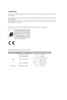
forth for an uncontrolled environment. This equipment should be installed and operated with minimum distance 20cm between the radiator are restricted to indoor usage only. Radio transmit power per transceiver type Function WiFi Bluetooth Frequency 2400-2483.5 MHz 5150-5250 MHz 5250-5350 MHz 5470- - ASRock Z370 Killer SLI/ac | User Manual - Page 5
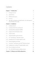
1 Introduction 1 1.1 Package Contents 1 1.2 Specifications 2 1.3 Motherboard Layout 7 1.4 I/O Panel 10 1.5 WiFi-802.11ac Module and ASRock WiFi 2.4/5 GHz Antennas (for Z370 Killer SLI/ac only) 13 Chapter 2 Installation 15 2.1 Installing the CPU 16 2.2 Installing the CPU Fan and - ASRock Z370 Killer SLI/ac | User Manual - Page 6
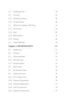
3.1 Installing Drivers 39 3.2 A-Tuning 40 3.2.1 Installing A-Tuning 40 3.2.2 Using A-Tuning 40 3.3 ASRock Live Update & APP Shop 43 3.3.1 UI Overview 43 3.3.2 Apps 44 3.3.3 BIOS & Drivers 47 3.3.4 Setting 48 3.4 ASRock RGB LED 49 Chapter 4 UEFI SETUP UTILITY 51 4.1 Introduction - ASRock Z370 Killer SLI/ac | User Manual - Page 7
4.6.6 ACPI Configuration 76 4.6.7 USB Configuration 78 4.6.8 Trusted Computing 79 4.7 Tools 80 4.8 Hardware Health Event Monitoring Screen 83 4.9 Security Screen 86 4.10 Boot Screen 87 4.11 Exit Screen 90 - ASRock Z370 Killer SLI/ac | User Manual - Page 8
list on ASRock's website as well. ASRock website http://www.asrock.com. 1.1 Package Contents • ASRock Z370 Killer SLI/ac / Z370 Killer SLI Motherboard (ATX Form Factor) • ASRock Z370 Killer SLI/ac / Z370 Killer SLI Quick Installation Guide • ASRock Z370 Killer SLI/ac / Z370 Killer SLI Support CD - ASRock Z370 Killer SLI/ac | User Manual - Page 9
as boot disks • 4 x PCI Express 3.0 x1 Slots (Flexible PCIe) • Supports AMD Quad CrossFireXTM and CrossFireXTM • Supports NVIDIA® Quad SLITM and SLITM • 1 x Vertical M.2 Socket (Key E) with the bundled WiFi- 802.11ac module (on the rear I/O) (for Z370 Killer SLI/ac only) • 15μ Gold Contact in VGA - ASRock Z370 Killer SLI/ac | User Manual - Page 10
Z370 Killer SLI/ac / Z370 Killer SLI Graphics Audio LAN • Intel® UHD Graphics Built-in Visuals and the VGA outputs can be supported only with processors which are GPU integrated. • Supports Codec) • Premium Blu-ray Audio support • Supports Surge Protection (ASRock Full Spike Protection) • Nichicon - ASRock Z370 Killer SLI/ac | User Manual - Page 11
Z370 Killer SLI/ac only) • Intel® 802.11ac WiFi Module • Supports IEEE 802.11a/b/g/n/ac • Supports Dual-Band (2.4/5 GHz) • Supports high speed wireless connections up to 433Mbps • Supports Bluetooth 4.2 / 3.0 + High speed class II Rear Panel I/O • 2 x Antenna Ports (for Z370 Killer SLI/ac only - ASRock Z370 Killer SLI/ac | User Manual - Page 12
Z370 Killer SLI/ac / Z370 Killer SLI * The CPU Fan Connector supports the CPU fan of maximum 1A (12W) fan power. • 2 x Chassis Fan Connectors (4-pin) (Smart Fan Speed Con- trol) • 1 x Chassis Optional/Water Pump Fan Connector (4-pin) * The Chassis Optional/Water Pump Fan supports the water cooler - ASRock Z370 Killer SLI/ac | User Manual - Page 13
, please visit our website: http://www.asrock.com Please realize that there is a certain risk involved with overclocking, including adjusting the setting in the BIOS, applying Untied Overclocking Technology, or using third-party overclocking tools. Overclocking may affect your system's stability, or - ASRock Z370 Killer SLI/ac | User Manual - Page 14
1.3 Motherboard Layout Z370 Killer SLI/ac Z370 Killer SLI/ac / Z370 Killer SLI PS2 Keyboard /Mouse USB 3.1 Gen1 T: USB1 B: USB2 HDMI1 M2_WIFI1 ATX12V1 CPU_FAN1 DDR4_A1 (64 bit, 288-pin module) DDR4_A2 (64 bit, 288-pin module) DDR4_B1 (64 - ASRock Z370 Killer SLI/ac | User Manual - Page 15
PCIE2 8 SATA_2_3 Z370 Killer SLI 9 Intel PCIE3 SATA_0_1 Z370 10 HD_AUDIO1 1 PCIE4 T B2 1 PCIE5 PCIE6 COM1 1 TPMS1 1 CMOS Battery RoHS CLRMOS1 1 RGB_LED1 1 CI1 1 PM_EO 1 USB_3_4 USB_1_2 1 1 Ultra M.2 PCIe Gen3 x4 M2_2 CHA_FAN1 CHA_FAN3/W_PUMP SPK_PLED1 BIOS ROM PANEL1 PLED - ASRock Z370 Killer SLI/ac | User Manual - Page 16
Z370 Killer SLI/ac / Z370 Killer SLI No. Description 1 ATX 12V Power Connector (ATX12V1) 2 2 x 288-pin DDR4 DIMM Slots (DDR4_A1, DDR4_B1) 3 2 x 288-pin DDR4 DIMM Slots (DDR4_A2, DDR4_B2) 4 CPU Fan Connector (CPU_FAN1) 5 ATX Power Connector (ATXPWR1) 6 USB 3.1 Gen1 Header (USB3_5_6) 7 Front Panel - ASRock Z370 Killer SLI/ac | User Manual - Page 17
1.4 I/O Panel Z370 Killer SLI/ac 1 46 2 3 57 15 14 13 12 11 10 98 No. Description No. Description 1 PS/2 Mouse/Keyboard Port 9 Optical SPDIF Out Port 2 USB 3.1 Gen1 Type-A Port ( - ASRock Z370 Killer SLI/ac | User Manual - Page 18
Z370 Killer SLI 1 Z370 Killer SLI/ac / Z370 Killer SLI 46 2 3 57 14 13 12 11 10 98 No. Description No. Description 1 PS/2 Mouse/Keyboard Port 8 Microphone (Pink) 2 USB 3.1 Gen1 Type-A Port (USB3_TA_1) 9 Optical SPDIF - ASRock Z370 Killer SLI/ac | User Manual - Page 19
* There are two LEDs on each LAN port. Please refer to the table below for the LAN port LED indications. ACT/LINK LED SPEED LED LAN Port Activity / Link LED Status Description Off Blinking On No Link Data Activity Link Speed LED Status Off Orange Green Description 10Mbps connection 100Mbps - ASRock Z370 Killer SLI/ac | User Manual - Page 20
Z370 Killer SLI/ac / Z370 Killer SLI 1.5 WiFi-802.11ac Module and ASRock WiFi 2.4/5 GHz Antennas (for Z370 Killer SLI/ac only) WiFi-802.11ac + BT Module This motherboard comes with an exclusive WiFi 802.11 a/b/g/n/ac + BT v4.2 module (pre-installed on the rear I/O panel) that offers support for - ASRock Z370 Killer SLI/ac | User Manual - Page 21
WiFi Antennas Installation Guide Step 1 Prepare the WiFi 2.4/5 GHz Antennas that come with the package. Step 2 Connect the two WiFi 2.4/5 GHz Antennas to the antenna connectors. Turn the antenna clockwise until it is securely connected. Step 3 Set the WiFi 2.4/5 GHz Antenna as shown in the - ASRock Z370 Killer SLI/ac | User Manual - Page 22
Z370 Killer SLI/ac / Z370 Killer SLI Chapter 2 Installation This is an ATX form factor motherboard. Before you install the motherboard, study the configuration of your chassis to ensure that the motherboard fits into it. Pre-installation Precautions Take note of the following precautions before you - ASRock Z370 Killer SLI/ac | User Manual - Page 23
2.1 Installing the CPU 1. Before you insert the 1151-Pin CPU into the socket, please check if the PnP cap is on the socket, the CPU into the socket if above situation is found. Otherwise, the CPU will be seriously damaged. 2. Unplug all power cables before installing the CPU. 1 A B 2 16 English - ASRock Z370 Killer SLI/ac | User Manual - Page 24
Z370 Killer SLI/ac / Z370 Killer SLI 3 4 5 17 English - ASRock Z370 Killer SLI/ac | User Manual - Page 25
Please save and replace the cover if the processor is removed. The cover must be placed if you wish to return the motherboard for after service. 18 English - ASRock Z370 Killer SLI/ac | User Manual - Page 26
Z370 Killer SLI/ac / Z370 Killer SLI 2.2 Installing the CPU Fan and Heatsink 1 2 CPU_FAN English 19 - ASRock Z370 Killer SLI/ac | User Manual - Page 27
Memory Modules (DIMM) This motherboard provides four 288-pin DDR4 (Double Data Rate 4) DIMM slots, and supports Dual Channel Memory Technology. 1. For dual channel configuration, you always need to install identical (the same brand, speed, size and chip-type) DDR4 DIMM pairs. 2. It is unable - ASRock Z370 Killer SLI/ac | User Manual - Page 28
Z370 Killer SLI/ac / Z370 Killer SLI 1 2 3 21 English - ASRock Z370 Killer SLI/ac | User Manual - Page 29
2.4 Expansion Slots (PCI Express Slots) There are 6 PCI Express slots on the motherboard. Before installing an expansion card, please make sure that the power supply is switched off or the power cord is unplugged. Please read the documentation of the - ASRock Z370 Killer SLI/ac | User Manual - Page 30
Z370 Killer SLI/ac / Z370 Killer SLI 2.5 Jumpers Setup The illustration shows how jumpers are setup. When . However, please do not clear the CMOS right after you update the BIOS. If you need to clear the CMOS when you just finish updating the BIOS, you must boot up the system first, and then shut - ASRock Z370 Killer SLI/ac | User Manual - Page 31
NOT place jumper caps over these headers and connectors. Placing jumper caps over the headers and connectors will cause permanent damage to the motherboard. System Panel Header (9-pin PANEL1) (see p.7 or 8, No. 11) PLED+ PLEDPWRBTN# GND 1 GND RESET# GND HDLEDHDLED+ Connect the power switch, reset - ASRock Z370 Killer SLI/ac | User Manual - Page 32
Z370 Killer SLI/ac / Z370 Killer SLI Serial ATA3 Connectors (SATA_0_1: see p.7 or 8, No. 10) (SATA_2_3: see p.7 or 8, No. 9) (SATA_4_5: + GND DUMMY 1 GND P+ PUSB_PWR There are two headers on this motherboard. Each USB 2.0 header can support two ports. USB 3.1 Gen1 Header (19-pin USB3_5_6) (see - ASRock Z370 Killer SLI/ac | User Manual - Page 33
support HDA to function correctly. Please follow the instructions in our manual and chassis manual to install your system. 2. If you use an AC'97 audio panel, please install 4 3 2 1 FAN_SPEED_CONTROL CHA_FAN_SPEED FAN_VOLTAGE GND This motherboard provides a 4-Pin water cooling chassis fan connector. - ASRock Z370 Killer SLI/ac | User Manual - Page 34
Z370 Killer SLI/ac / Z370 Killer SLI CPU Fan Connector (4-pin CPU_FAN1) (see p.7 or 8, No. 4) ATX Power Connector (24-pin ATXPWR1) (see p.7 or 8, No. 5) ATX 12V Power Connector (8-pin ATX12V1) (see p.7 or 8, No. 1) Thunderbolt AIC Connector (5-pin TB2) (see p.7 or 8, No. 21) Serial Port Header (9- - ASRock Z370 Killer SLI/ac | User Manual - Page 35
SMB_CLK_MAIN SMB_DATA_MAIN LAD2 LAD1 GND S_PWRDWN# SERIRQ# GND This motherboard supports CASE OPEN detection feature that detects if the chassis cove install the RGB LED cable in the wrong orientation; otherwise, the cable may be damaged. *Please refer to page 49 for for further instructions on - ASRock Z370 Killer SLI/ac | User Manual - Page 36
Z370 Killer SLI/ac / Z370 Killer SLI 2.7 SLITM and Quad SLITM Operation Guide This motherboard supports NVIDIA® SLITM and Quad SLITM (Scalable Link Interface) technology that allows you to install that your graphics card driver supports NVIDIA® SLITM technology. Download the drivers from the NVIDIA® - ASRock Z370 Killer SLI/ac | User Manual - Page 37
SLI_HB_ Bridge_2S Card to the goldfingers on each graphics card. Make sure the ASRock SLI_ HB_Bridge_2S Card is firmly in place. SLI_HB_Bridge_2S Card ASRock SLI_HB_Bridge_2S Card Step 4 Connect a VGA cable or a DVI cable to the monitor connector or the DVI connector of the graphics card that is - ASRock Z370 Killer SLI/ac | User Manual - Page 38
Z370 Killer SLI/ac / Z370 Killer SLI 2.7.2 Driver Installation and Setup Install the graphics card drivers to your system. 1 Double-click the NVIDIA Control Panel icon in the Windows® system tray. Step 2 In the left pane, click Set SLI and PhysX configuration. Then select Maximize 3D performance and - ASRock Z370 Killer SLI/ac | User Manual - Page 39
Guide This motherboard supports CrossFireXTM and Quad CrossFireXTM that allows you to install up to three identical PCI Express x16 graphics cards. 1. You should only use identical CrossFireXTM-ready graphics cards that are AMD certified. 2. Make sure that your graphics card driver supports - ASRock Z370 Killer SLI/ac | User Manual - Page 40
Z370 Killer SLI/ac / Z370 Killer SLI Step 3 Connect a VGA cable or a DVI cable to the monitor connector or the DVI connector of the graphics card that is inserted to PCIE2 slot. 33 English - ASRock Z370 Killer SLI/ac | User Manual - Page 41
AMD's website for AMD driver updates. Step 3 Install the required drivers and CATALYST Control Center then restart your computer. Please check AMD's website for details. AMD Catalyst Control Center Step 4 Double-click the AMD Catalyst Control Center icon in the Windows® system tray. Step 5 In - ASRock Z370 Killer SLI/ac | User Manual - Page 42
Z370 Killer SLI/ac / Z370 Killer SLI 2.9 M.2_SSD (NGFF) Module Installation Guide The M.2, also known as the Next Generation Form Factor (NGFF), is a small size and versatile card edge connector that aims to replace mPCIe and mSATA. The Ultra M.2 Sockets (M2_1 and M2_2) support SATA3 6.0 Gb/s - ASRock Z370 Killer SLI/ac | User Manual - Page 43
protective film on the nut to be used. Hand tighten the standoff into the desired nut location on the motherboard. Step 5 Align and gently insert the M.2 (NGFF) SSD module into the M.2 slot. Please be aware that the M.2 (NGFF) SSD module only fits in one orientation. Step 6 Tighten the screw with - ASRock Z370 Killer SLI/ac | User Manual - Page 44
Z370 Killer SLI/ac / Z370 Killer SLI M.2_SSD (NGFF) Module Support List Vendor ADATA ADATA ADATA ADATA ADATA ADATA ADATA ADATA ADATA ADATA Apacer Corsair Crucial Crucial Intel Intel Intel Kingston Kingston Kingston OCZ PATRIOT Plextor - ASRock Z370 Killer SLI/ac | User Manual - Page 45
-2280B-RD VLM100-240G-2280RGB VSM100-240G-2280 VLM100-240G-2280B-RD WDS100T1B0B-00AS40 WDS240G1G0B-00RC30 WDS256G1X0C-00ENX0 (NVME) WDS512G1X0C-00ENX0 (NVME) For the latest updates of M.2_SSD (NFGG) module support list, please visit our website for details: http://www.asrock.com English 38 - ASRock Z370 Killer SLI/ac | User Manual - Page 46
Z370 Killer SLI/ac / Z370 Killer SLI Chapter 3 Software and Utilities Operation 3.1 Installing Drivers The Support CD that comes with the motherboard contains necessary drivers and useful utilities that enhance the motherboard's features. Running The Support CD To begin using the support CD, insert - ASRock Z370 Killer SLI/ac | User Manual - Page 47
multi purpose software suite with a new interface, more new features and improved utilities. 3.2.1 Installing A-Tuning A-Tuning can be downloaded from ASRock Live Update & APP Shop. After the installation, you will find the icon "A-Tuning" on your desktop. Double-click the "ATuning" icon, A-Tuning - ASRock Z370 Killer SLI/ac | User Manual - Page 48
OC Tweaker Configurations for overclocking the system. Z370 Killer SLI/ac / Z370 Killer SLI System Info View information about the system. *The System Browser tab may not appear for certain models. 41 English - ASRock Z370 Killer SLI/ac | User Manual - Page 49
five different fan speeds using the graph. The fans will automatically shift to the next speed level when the assigned temperature is met. Settings Configure ASRock A-Tuning. Click to select "Auto run at Windows Startup" if you want A-Tuning to be launched when you start up the - ASRock Z370 Killer SLI/ac | User Manual - Page 50
Z370 Killer SLI/ac / Z370 Killer SLI 3.3 ASRock Live Update & APP Shop The ASRock Live Update & APP Shop is an online store for purchasing and downloading software applications for your ASRock computer. You can quickly and easily install various apps and support utilities. With ASRock Live Update & - ASRock Z370 Killer SLI/ac | User Manual - Page 51
the app and whether you have already intalled it or not. - The red icon displays the price or "Free" if the app is free of charge. - The green "Installed" icon means the app is installed on your computer. Step 2 Click on the app icon to see more details about the selected app. 44 - ASRock Z370 Killer SLI/ac | User Manual - Page 52
Z370 Killer SLI/ac / Z370 Killer SLI Step 3 If you want to install the app, click on the red icon to start downloading. Step 4 When installation completes, you can find the green "Installed" icon appears on the upper right corner. English To uninstall it, simply click on the trash can icon . * - ASRock Z370 Killer SLI/ac | User Manual - Page 53
Upgrading an App You can only upgrade the apps you have already installed. When there is an available new version for your app, you will find the mark of "New Version" appears below the installed app icon. Step 1 Click on the app icon to see more details. Step 2 Click on the yellow icon - ASRock Z370 Killer SLI/ac | User Manual - Page 54
Z370 Killer SLI/ac / Z370 Killer SLI 3.3.3 BIOS & Drivers Installing BIOS or Drivers When the "BIOS & Drivers" tab is selected, you will see a list of recommended or critical updates for the BIOS or drivers. Please update them all soon. Step 1 Please check the item information before update. Click - ASRock Z370 Killer SLI/ac | User Manual - Page 55
3.3.4 Setting In the "Setting" page, you can change the language, select the server location, and determine if you want to automatically run the ASRock Live Update & APP Shop on Windows startup. 48 English - ASRock Z370 Killer SLI/ac | User Manual - Page 56
Z370 Killer SLI/ac / Z370 Killer SLI 3.4 ASRock RGB LED ASRock RGB LED is a lighting control utility specifically designed for unique individuals with sophisticated tastes to build their own stylish colorful lighting system. Simply by connecting - ASRock Z370 Killer SLI/ac | User Manual - Page 57
RGB LED utility. Download this utility from the ASRock Live Update & APP Shop and start coloring your PC style your way! Drag the tab to customize your preference. Toggle on/off the RGB LED switch Sync RGB LED effects for all LED regions of the motherboard Select a RGB LED light effect from the - ASRock Z370 Killer SLI/ac | User Manual - Page 58
Killer SLI/ac / Z370 Killer SLI Chapter 4 UEFI SETUP UTILITY 4.1 Introduction This section explains how to use the UEFI SETUP UTILITY to configure your system. You may run the UEFI SETUP UTILITY by pressing or right after you power on the computer, otherwise, the Power-On-Self-Test (POST - ASRock Z370 Killer SLI/ac | User Manual - Page 59
4.2 EZ Mode The EZ Mode screen appears when you enter the BIOS setup program by default. EZ mode is a dashboard which contains multiple readings of the system's current status. You can check the most crucial information of - ASRock Z370 Killer SLI/ac | User Manual - Page 60
Z370 Killer SLI/ac / Z370 Killer SLI 4.3 Advanced Mode The Advanced Mode provides more options to configure the BIOS settings. Refer to the following setting system time/date information OC Tweaker For overclocking configurations Advanced For advanced system configurations Tool Useful - ASRock Z370 Killer SLI/ac | User Manual - Page 61
4.3.2 Navigation Keys Use < > key or < > key to choose among the selections on the menu bar, and use < > key or < > key to move the cursor up or down to select items, then press to get into the sub screen. You can also use the mouse to click your required item. Please check the following - ASRock Z370 Killer SLI/ac | User Manual - Page 62
Z370 Killer SLI/ac / Z370 Killer SLI 4.4 Main Screen When you enter the UEFI SETUP UTILITY, the Main screen will appear and display the system overview. My Favorite Display your collection of BIOS items. Press F5 to add/remove your favorite items. 55 English - ASRock Z370 Killer SLI/ac | User Manual - Page 63
appears only when your CPU supports this function. This option appears only when you adopt K-Series CPU. Load Optimized CPU OC Setting You can use this option to load optimized CPU overclocking setting. Please note that overclocking may cause damage to your CPU and motherboard. It should be done at - ASRock Z370 Killer SLI/ac | User Manual - Page 64
Z370 Killer SLI/ac / Z370 Killer SLI CPU Configuration Multi Core Enhancement Improve the system's reduce electromagnetic interference for passing EMI tests. Disable to achieve higher clock speeds when overclocking. CPU BCLK Amplitude Configure the CPU BCLK Amplitude. CPU Slew Rate Configure the CPU - ASRock Z370 Killer SLI/ac | User Manual - Page 65
frequency when the operating system requests the highest performance state. Intel Speed Shift Technology Enable/Disable Intel Speed Shift Technology support. Enabling will expose the CPPC v2 interface to allow for hardware controlled P-states. Long Duration Power Limit Configure Package Power - ASRock Z370 Killer SLI/ac | User Manual - Page 66
Z370 Killer SLI/ac / Z370 Killer SLI Short DRAM Timing Configuration Load XMP Setting Load XMP settings to overclock the memory and perform beyond standard specifications. BCLK Frequency Frequency If [Auto] is selected, the motherboard will detect the memory module(s) inserted and assign the - ASRock Z370 Killer SLI/ac | User Manual - Page 67
CAS# Latency (tCL) The time between sending a column address to the memory and the beginning of the data in response. RAS# to CAS# Delay and Row Precharge (tRCDtRP) RAS# to CAS# Delay : The number of clock cycles required between the opening of a row of memory and accessing columns within it. Row - ASRock Z370 Killer SLI/ac | User Manual - Page 68
Z370 Killer SLI/ac / Z370 Killer SLI Write to Read Delay (tWTR_S) The number of clocks between between a read command to a row precharge command to the same rank. Four Activate Window (tFAW) The time window in which four activates are allowed the same rank. CAS Write Latency (tCWL) Configure CAS - ASRock Z370 Killer SLI/ac | User Manual - Page 69
tRDWR_dr Configure between module read to write delay. tRDWR_dd Configure between module read to write delay. tWRRD_sg Configure between module write to read delay. tWRRD_dg Configure between module write to read delay. tWRRD_dr Configure between module write to read delay. tWRRD_dd Configure - ASRock Z370 Killer SLI/ac | User Manual - Page 70
Z370 Killer SLI/ac / Z370 Killer SLI RTL (CH B) Configure round trip latency for channel B. IO-L (CH A) Configure IO latency for channel A. PARK for channel B. ODT NOM (CH A) Use this to change ODT (CH A) Auto/Manual settings. The default is [Auto]. ODT NOM (CH B) Use this to change ODT (CH B) Auto - ASRock Z370 Killer SLI/ac | User Manual - Page 71
1. Dll Bandwidth 2 Configure the Dll Bandwidth 2. Dll Bandwidth 3 Configure the Dll Bandwidth 3. Command Tristate Configure the Command Tristate Support. Realtime Memory Timing Configure the realtime memory timings. [Enabled] The system will allow performing realtime memory timing changes after - ASRock Z370 Killer SLI/ac | User Manual - Page 72
Z370 Killer SLI/ac / Z370 Killer SLI Use this to configure DRAM Voltage. The default value is [Auto]. DRAM Activating Power Supply Configure the voltage for the DRAM Activating Power Supply. PCH +1.0 - ASRock Z370 Killer SLI/ac | User Manual - Page 73
Memory Controller PLL Voltage Default is 0.900V. Each step is 0.015V. Adding 9 -15 steps will help CPU PLL to lock internal clock during High frequency under Ln2 cooling. For example: 1.020V 1.125V will be proper value. Bu the voltage level will be different on each processor. User has to find the - ASRock Z370 Killer SLI/ac | User Manual - Page 74
Z370 Killer SLI/ac / Z370 Killer SLI 4.6 Advanced Screen In this section, you may set the is selected, the resolution will be set to 1920 x 1080 if the monitor supports Full HD resolution. If the monitor does not support Full HD resolution, then the resolution will be set to 1024 x 768. When - ASRock Z370 Killer SLI/ac | User Manual - Page 75
4.6.1 CPU Configuration Active Processor Cores Select the number of cores to enable in each processor package. CPU C States Support Enable CPU C States Support for power saving. It is recommended to keep C3, C6 and C7 all enabled for better power saving. Enhanced Halt State (C1E) Enable Enhanced - ASRock Z370 Killer SLI/ac | User Manual - Page 76
Z370 Killer SLI/ac / Z370 Killer SLI CFG Lock This item allows you to disable or enable the CFG Lock. CPU for better performance. Software Guard Extensions (SGX) Intel SGX is a set of new CPU instructions that can be used by applications to set aside private regions of code and data. 69 English - ASRock Z370 Killer SLI/ac | User Manual - Page 77
Dynamic assignment would adjust TOLUD automatically based on largest MMIO length of installed graphic controller. Above 4G Decoding Enable or disable 64bit capable Devices decoded in Above 4G Address Space (only if the system supports 64 bit PCI decoding). VT-d Intel® Virtualization Technology for - ASRock Z370 Killer SLI/ac | User Manual - Page 78
Z370 Killer SLI/ac / Z370 Killer SLI PCIE3 Link on CPU side of the DMI Link. PCH DMI ASPM Support This option enables/disables the ASPM support for all PCH DMI devices. IOAPIC 24-119 Entries I/O external graphics card is installed. Select enable to keep the integrated graphics enabled at all times - ASRock Z370 Killer SLI/ac | User Manual - Page 79
onboard HD audio and automatically disable it when a sound card is installed. Front Panel Enable/disable front panel HD audio. Onboard HDMI HD /disable the WiFi module's connectivity. Deep Sleep Configure deep sleep mode for power saving when the computer is shut down. Restore on AC/Power Loss - ASRock Z370 Killer SLI/ac | User Manual - Page 80
4.6.3 Storage Configuration Z370 Killer SLI/ac / Z370 Killer SLI SATA Controller(s) Enable/disable the SATA controllers. SATA Controller Speed Indicates the maximum speed the SATA controller can support. SATA Mode Selection AHCI: Supports new features that improve performance. RAID: Combine - ASRock Z370 Killer SLI/ac | User Manual - Page 81
™ Intel(R) Thunderbolt Technology Enable/Disable the Intel(R) Thunderbolt function. Security Level Allows you to choose a security level for the Thunderbolt ports. AR AIC Support Enable or disable to support AR AIC card. TBT Host Router Enable the host router based on ports available. 74 English - ASRock Z370 Killer SLI/ac | User Manual - Page 82
4.6.5 Super IO Configuration Z370 Killer SLI/ac / Z370 Killer SLI Serial Port Enable or disable the Serial port. Serial Port Address Select the address of the Serial port. PS2 Y-Cable Enable the PS2 Y-Cable or set this option to Auto. 75 English - ASRock Z370 Killer SLI/ac | User Manual - Page 83
4.6.6 ACPI Configuration Suspend to RAM Select disable for ACPI suspend type S1. It is recommended to select auto for ACPI S3 power saving. ACPI HEPT Table Enable the High Precision - ASRock Z370 Killer SLI/ac | User Manual - Page 84
Z370 Killer SLI/ac / Z370 Killer SLI USB Mouse Power On Allow the system to be waked up by an USB mouse. 77 English - ASRock Z370 Killer SLI/ac | User Manual - Page 85
disable legacy USB support. Select UEFI Setup Only to support USB devices under the UEFI setup and Windows/Linux operating systems support for non-USB aware OSes. XHCI Hand-off This is a workaround for OSes without XHCI hand-off support. The XHCI ownership change should be claimed by XHCI driver - ASRock Z370 Killer SLI/ac | User Manual - Page 86
4.6.8 Trusted Computing Z370 Killer SLI/ac / Z370 Killer SLI Security Device Support Enable or disable BIOS support for security device. English 79 - ASRock Z370 Killer SLI/ac | User Manual - Page 87
unique PC style easily. UEFI Tech Service Contact ASRock Tech Service if you are having trouble with your PC. Please setup network configuration before using UEFI Tech Service. Easy RAID Installer Easy RAID Installer helps you to copy the RAID driver from the support CD to your USB storage device - ASRock Z370 Killer SLI/ac | User Manual - Page 88
Z370 Killer SLI/ac / Z370 Killer SLI Boot Manager Boot Manager is specifically designed for IP), Auto ASRock Internet Flash downloads and updates the latest UEFI firmware version from our servers for you. Please setup network configuration before using Internet Flash. *For BIOS backup and recovery - ASRock Z370 Killer SLI/ac | User Manual - Page 89
Network Configuration Use this to configure internet connection settings for Internet Flash. Internet Setting Enable or disable sound effects in the setup utility. UEFI Download Server Select a server to download the UEFI firmware. 82 English - ASRock Z370 Killer SLI/ac | User Manual - Page 90
Z370 Killer SLI/ac / Z370 Killer SLI 4.8 Hardware Health Event Monitoring Screen This section allows you to monitor the status of the hardware on your system, including the parameters of the CPU temperature, motherboard temperature, fan speed and voltage. Fan Tuning Measure Fan Min Duty Cycle. Fan- - ASRock Z370 Killer SLI/ac | User Manual - Page 91
Chassis Fan 1 Setting Select a fan mode for Chassis Fan 1, or choose Customize to set 5 CPU temperatures and assign a respective fan speed for each temperature. Chassis Fan 1 Temp Source Select a fan temperature source for Chassis Fan 1. Chassis Fan 1 Step Up Set the value of Chassis Fan 1 Step Up. - ASRock Z370 Killer SLI/ac | User Manual - Page 92
Z370 Killer SLI/ac / Z370 Killer SLI Chassis Fan 3 Step Up Set the value of Chassis Fan 3 Step Up. Chassis Fan 3 Step Down Set the value of Chassis Fan 3 Step Down. Over Temperature Protection When Over Temperature Protection is enabled, the system automatically shuts down when the motherboard is - ASRock Z370 Killer SLI/ac | User Manual - Page 93
settings in the UEFI Setup Utility. Leave it blank and press enter to remove the password. Secure Boot Use this item to enable or disable support for Secure Boot. Intel(R) Platform Trust Technology Enable/disable Intel PTT in ME. Disable this option to use discrete TPM Module. 86 English - ASRock Z370 Killer SLI/ac | User Manual - Page 94
SLI/ac / Z370 Killer SLI 4.10 Boot Screen This section displays the available devices on your system for you to configure the boot settings and the boot priority. Fast Boot Fast Boot minimizes your computer's boot time. In fast mode you may not boot from an USB storage device. The VBIOS must support - ASRock Z370 Killer SLI/ac | User Manual - Page 95
display the boot logo or disable to show normal POST messages. AddOn ROM Display Enable AddOn ROM Display to the system automatically restores the default settings. CSM (Compatibility Support Module) CSM Enable to launch the Compatibility Support Module. Please do not disable unless you're running a - ASRock Z370 Killer SLI/ac | User Manual - Page 96
Z370 Killer SLI/ac / Z370 Killer SLI Launch Storage OpROM Policy Select UEFI only to run those that support UEFI option ROM only. Select Legacy only to run those that support legacy option ROM only. Select Do not launch to not execute both legacy and UEFI option ROM. Launch Video OpROM Policy Select - ASRock Z370 Killer SLI/ac | User Manual - Page 97
4.11 Exit Screen Save Changes and Exit When you select this option the following message, "Save configuration changes and exit setup?" will pop out. Select [OK] to save changes and exit the UEFI SETUP UTILITY. Discard Changes and Exit When you select this option the following message, "Discard - ASRock Z370 Killer SLI/ac | User Manual - Page 98
or want to know more about ASRock, you're welcome to visit ASRock's website at http://www.asrock.com; or you may contact your dealer for further information. For technical questions, please submit a support request form at http://www.asrock.com/support/tsd.asp ASRock Incorporation 2F., No.37, Sec - ASRock Z370 Killer SLI/ac | User Manual - Page 99
2 Section 2.1077(a) Responsible Party Name: ASRock Incorporation Address: 13848 Magnolia Ave, Chino, CA91710 Phone/Fax No: +1-909-590-8308/+1-909-590-1026 hereby declares that the product Product Name : Motherboard Model Number : Z370 Killer SLI/ac / Z370 Killer SLI Conforms to the following speci - ASRock Z370 Killer SLI/ac | User Manual - Page 100
EU Declaration of Conformity For the following equipment: Motherboard (Product Name) Z370 Killer SLI/ac / Z370 Killer SLI / ASRock (Model Designation / Trade Name) ASRock Incorporation (Manufacturer Name) 2F., No.37, Sec. 2, Jhongyang S. Rd., Beitou District, Taipei City 112, Taiwan (R.O.C.) (
-
 1
1 -
 2
2 -
 3
3 -
 4
4 -
 5
5 -
 6
6 -
 7
7 -
8
-
9
-
10
-
11
-
12
-
13
-
14
-
15
-
16
-
17
-
18
-
19
-
20
-
21
-
22
-
23
-
24
-
25
-
26
-
27
-
28
-
29
-
30
-
31
-
32
-
33
-
34
-
35
-
36
-
37
-
38
-
39
-
40
-
41
-
42
-
43
-
44
-
45
-
46
-
47
-
48
-
49
-
50
-
51
-
52
-
53
-
54
-
55
-
56
-
57
-
58
-
59
-
60
-
61
-
62
-
63
-
64
-
65
-
66
-
67
-
68
-
69
-
70
-
71
-
72
-
73
-
74
-
75
-
76
-
77
-
78
-
79
-
80
-
81
-
82
-
83
-
84
-
85
-
86
-
87
-
88
-
89
-
90
-
91
-
92
-
93
-
94
-
95
-
96
-
97
-
98
-
99
-
100
 |
 |