ASRock Z590 Extreme User Manual
ASRock Z590 Extreme Manual
 |
View all ASRock Z590 Extreme manuals
Add to My Manuals
Save this manual to your list of manuals |
ASRock Z590 Extreme manual content summary:
- ASRock Z590 Extreme | User Manual - Page 1
- ASRock Z590 Extreme | User Manual - Page 2
documentation are furnished for informational use only and subject to change without notice, and should not be constructed as a commitment by ASRock. ASRock assumes no responsibility for any errors or omissions that may appear in this documentation. With respect to the contents of this documentation - ASRock Z590 Extreme | User Manual - Page 3
not amount to a major failure. If you require assistance please call ASRock Tel : +886-2-28965588 ext.123 (Standard International call charges apply) other text or file. (e) Intel has no obligation to provide any support, technical assistance or updates for the Software. OWNERSHIP OF SOFTWARE AND - ASRock Z590 Extreme | User Manual - Page 4
ES OF ANY KIND WHETHER UNDER THIS AGREEMENT OR OTHERWISE, EVEN IF INTEL HAS BEEN ADVISED OF THE POSSIBILITY OF SUCH DAMAGES. LICENSE TO USE COMMENTS AND SUGGESTIONS. This Agreement does NOT obligate Licensee to provide Intel with comments or suggestions regarding the Software. However, if Licensee - ASRock Z590 Extreme | User Manual - Page 5
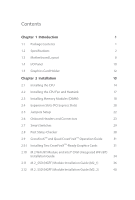
Setup 22 2.6 Onboard Headers and Connectors 23 2.7 Smart Switches 29 2.8 Post Status Checker 30 2.9 CrossFireXTM and Quad CrossFireXTM Operation Guide 31 2.9.1 Installing Two CrossFireXTM-Ready Graphics Cards 31 2.10 M.2 WiFi/BT Module and Intel® CNVi (Integrated WiFi/BT) Installation - ASRock Z590 Extreme | User Manual - Page 6
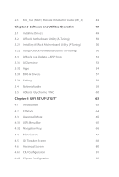
2.13 M.2_SSD (NGFF) Module Installation Guide (M2_3) 44 Chapter 3 Software and Utilities Operation 49 3.1 Installing Drivers 49 3.2 ASRock Motherboard Utility (A-Tuning) 50 3.2.1 Installing ASRock Motherboard Utility (A-Tuning) 50 3.2.2 Using ASRock Motherboard Utility (A-Tuning) 50 3.3 - ASRock Z590 Extreme | User Manual - Page 7
4.6.3 Storage Configuration 86 4.6.4 Intel(R) Thunderbolt 87 4.6.5 Super IO Configuration 88 4.6.6 ACPI Configuration 89 4.6.7 USB Configuration 90 4.6.8 Trusted Computing 91 4.7 Tools 92 4.8 Hardware Health Event Monitoring Screen 94 4.9 Security Screen 98 4.10 Boot Screen 99 4. - ASRock Z590 Extreme | User Manual - Page 8
the latest VGA cards and CPU support list on ASRock's website as well. ASRock website http://www.asrock.com. 1.1 Package Contents • ASRock Z590 Extreme Motherboard (ATX Form Factor) • ASRock Z590 Extreme Quick Installation Guide • ASRock Z590 Extreme Support CD • 4 x Serial ATA (SATA) Data Cables - ASRock Z590 Extreme | User Manual - Page 9
DDR4 up to 2666. * Please refer to Memory Support List on ASRock's website for more information. (http://www.asrock.com/) • Supports ECC UDIMM memory modules (operate in non- ECC mode) • Max. capacity of system memory: 128GB • Supports Intel® Extreme Memory Profile (XMP) 2.0 • 15μ Gold Contact in - ASRock Z590 Extreme | User Manual - Page 10
Z590 Extreme Graphics Audio • 3 x PCI Express 3.0 x1 Slots • Supports AMD Quad CrossFireXTM and CrossFireXTM • 1 x M.2 Socket (Key E), supports type 2230 WiFi/BT PCIe WiFi module and Intel® CNVi (Integrated WiFi/BT) • 15μ Gold Contact in VGA PCIe Slot (PCIE1) • Intel® UHD Graphics Built- - ASRock Z590 Extreme | User Manual - Page 11
Channel • Gold Audio Jacks • 15μ Gold Audio Connector • Nahimic Audio LAN 1 x 2.5 Gigabit LAN 10/100/1000/2500 Mb/s (Dragon RTL8125BG) • Supports Dragon 2.5G LAN Software - Smart Auto Adjust Bandwidth Control - Visual User Friendly UI - Visual Network Usage Statistics - Optimized Default Setting - ASRock Z590 Extreme | User Manual - Page 12
Z590 Extreme • 2 x USB 2.0 Ports (Supports ESD Protection) • 2 x RJ-45 LAN Ports with LED (ACT/LINK LED and SPEED LED) • HD Audio Jacks: Rear Speaker / Central / Bass / Line in / Front Speaker / Microphone (Gold Audio Jacks) Storage • 6 x SATA3 6.0 Gb/s Connectors, support RAID (RAID 0, RAID 1, - ASRock Z590 Extreme | User Manual - Page 13
Connector) • 1 x Thunderbolt AIC Connector (5-pin) (Supports ASRock Thunderbolt 4 AIC Card) • 2 x USB 2.0 Headers (Support 4 USB 2.0 ports) (Supports ESD Protection) • 2 x USB 3.2 Gen1 Headers (Support 4 USB 3.2 Gen1 ports) (ASMedia ASM1074 hub) (Supports ESD Protection) • 1 x Front Panel Type C USB - ASRock Z590 Extreme | User Manual - Page 14
Z590 Extreme OS Certifications • Microsoft® Windows® 10 64-bit • FCC, CE • ErP/EuP ready (ErP/EuP ready power supply is required) * For detailed product information, please visit our website: http://www.asrock.com Please realize that there is a certain risk involved with overclocking, including - ASRock Z590 Extreme | User Manual - Page 15
USB 2.0 T: USB_1 B: USB_2 PS2 Keyboard /Mouse 1.3 Motherboard Layout 1 2 ATX12V1 ATX12V2 34 56 CPU_FAN2/WP 1 ADDR_LED2 1 7 RGB_LED2 Power 8 Reset 9 HDMI1 Z590 Extreme DDR4_A1 (64 bit, 288-pin module) DDR4_A2 (64 bit, 288-pin module) DDR4_B1 (64 bit, 288-pin module) DDR4_B2 (64 bit, - ASRock Z590 Extreme | User Manual - Page 16
(RGB_LED1) 31 Addressable LED Header (ADDR_LED1) 32 Front Panel Audio Header (HD_AUDIO1) 33 Thunderbolt AIC Connector (TB1) 34 Chassis/Water Pump Fan Connector (CHA_FAN1/WP) Z590 Extreme 9 English - ASRock Z590 Extreme | User Manual - Page 17
1.4 I/O Panel 1 46 2 3 57 15 14 13 No. Description 1 USB 2.0 Ports (USB_1_2) 2 LAN RJ-45 Port (Intel® I219V)* 3 2.5G LAN RJ-45 Port (Dragon RTL8125BG)** 4 Central / Bass (Orange) 5 Rear Speaker (Black) 6 Line In (Light Blue) 7 Front Speaker (Lime)*** 11 10 98 12 No. Description 8 - ASRock Z590 Extreme | User Manual - Page 18
Z590 Extreme * There are two LEDs on each LAN port. Please refer to the table below for the LAN 2 4 6 8 Front Speaker (No. 7) V V V V Rear Speaker (No. 5) -V V V Central / Bass (No. 4) --V V Line In (No. 6) ---V **** Ultra USB Power is supported on USB3_12 ports. ACPI wake-up function is not - ASRock Z590 Extreme | User Manual - Page 19
1.5 Graphics Card Holder Installing the Graphics Card Holder Before installing the Graphics Card Holder , please make sure that your motherboard is properly installed into a PC case. Step 1 Secure the Graphics Card Holder to the chassis with 2 screws. Type A Type B *There are two types of screws - ASRock Z590 Extreme | User Manual - Page 20
Z590 Extreme Chapter 2 Installation This is an ATX form factor motherboard. Before you install the motherboard, study the configuration of your chassis to ensure that the motherboard - ASRock Z590 Extreme | User Manual - Page 21
2.1 Installing the CPU 1. Before you insert the 1200-Pin CPU into the socket, please check if the PnP cap is on the socket, if the CPU surface is unclean, or if there are any bent pins in the socket. Do not force to insert the CPU into the socket if above situation is found. Otherwise, the CPU will - ASRock Z590 Extreme | User Manual - Page 22
Z590 Extreme 3 4 5 15 English - ASRock Z590 Extreme | User Manual - Page 23
Please save and replace the cover if the processor is removed. The cover must be placed if you wish to return the motherboard for after service. 16 English - ASRock Z590 Extreme | User Manual - Page 24
2.2 Installing the CPU Fan and Heatsink Z590 Extreme 1 2 CPU_FAN 17 English - ASRock Z590 Extreme | User Manual - Page 25
2.3 Installing Memory Modules (DIMM) This motherboard provides four 288-pin DDR4 (Double Data Rate 4) DIMM slots, and supports Dual Channel Memory Technology. 1. For dual channel configuration, you always need to install identical (the same brand, speed, size and chip-type) DDR4 DIMM pairs. 2. - ASRock Z590 Extreme | User Manual - Page 26
Z590 Extreme 1 2 3 19 English - ASRock Z590 Extreme | User Manual - Page 27
2.4 Expansion Slots (PCI Express Slots) There are 5 PCI Express slots on the motherboard. Before installing an expansion card, please make sure that the power supply is switched off or the power cord is unplugged. Please read the documentation of the expansion card and make necessary hardware - ASRock Z590 Extreme | User Manual - Page 28
Gen Intel® CoreTM Processors: PCIE1 Single Graphics Card Gen3x16 Two Graphics Cards in CrossFireXTM Mode Gen3x16 PCIE3 N/A Gen3x4 PCIE3 N/A Gen3x4 Z590 Extreme For a better thermal environment, please connect a chassis fan to the motherboard's chassis fan connector (CHA_FAN1~5/WP) when using - ASRock Z590 Extreme | User Manual - Page 29
2.5 Jumpers Setup The illustration shows how jumpers are setup. When the jumper cap is placed on the pins, the jumper is "Short". If no jumper cap is placed on the pins, the jumper is "Open". Clear CMOS Jumper (CLRMOS1) (see p.8, No. 23) Short: Clear CMOS Open: Default CLRMOS1 allows you to clear - ASRock Z590 Extreme | User Manual - Page 30
Z590 Extreme 2.6 Onboard Headers and Connectors Onboard headers and connectors are NOT jumpers. Do NOT place jumper caps over these headers and connectors. Placing jumper caps over - ASRock Z590 Extreme | User Manual - Page 31
USB_5_6) (see p.8, No. 27) USB_PWR PP+ GND DUMMY 1 GND P+ PUSB_PWR There are two headers on this motherboard. Each USB 2.0 header can support two ports. USB 3.2 Gen1 Headers (19-pin USB3_3_4) (see p.8, No. 28) (19-pin USB3_5_6) (see p.8, No. 12) IntA_P_D+ IntA_P_DGND IntA_P_SSTX+ IntA_P_SSTXGND - ASRock Z590 Extreme | User Manual - Page 32
Z590 Extreme Front Panel Type C USB 3.2 Gen2x2 Header (20-pin USB31_TC_2) (see p.8, No. 1. High Definition Audio supports Jack Sensing, but the panel wire on the chassis must support HDA to function correctly. Please follow the instructions in our manual and chassis manual to install your system. - ASRock Z590 Extreme | User Manual - Page 33
(4-pin CHA_FAN2/WP) (see p.8, No. 25) (4-pin CHA_FAN3/WP) (see p.8, No. 19) (4-pin CHA_FAN4/WP) (see p.8, No. 24) (4-pin CHA_FAN5/WP) (see p.8, No. 29) GND FAN_VOLTAGE FAN_SPEED FAN_SPEED_CONTROL 1 2 34 CPU Fan Connector (4-pin CPU_FAN1) (see p.8, No. 13) FAN_SPEED_CONTROL FAN_SPEED + 12V GN D 4 - ASRock Z590 Extreme | User Manual - Page 34
Z590 Extreme ATX 12V Power Connectors (8-pin ATX12V1) (see p.8, No. 1) (8-pin ATX12V2) (see p.8, No. CLK SPI_MOSI RST# TPM_PIRQ 1 SPI_TPM_CS# GND RSMRST# SPI_MISO SPI_CS0 SPI_DQ2 This connector supports SPI Trusted Platform Module (TPM) system, which can securely store keys, digital certificates - ASRock Z590 Extreme | User Manual - Page 35
: Never install the RGB LED cable in the wrong orientation; otherwise, the cable may be damaged. *Please refer to page 60 for further instructions on these two headers. These two Addressable headers are used to connect Addressable LED extension cable which allows users to choose from various LED - ASRock Z590 Extreme | User Manual - Page 36
Z590 Extreme 2.7 Smart Switches The motherboard has two smart switches: Power Button and Reset Button, allowing users to quickly turn on/off the system or reset the - ASRock Z590 Extreme | User Manual - Page 37
2.8 Post Status Checker Post Status Checker (PSC) diagnoses the computer when users power on the machine. It emits a red light to indicate whether the CPU, memory, VGA or storage is dysfunctional. The lights go off if the four mentioned above are functioning normally. 30 English - ASRock Z590 Extreme | User Manual - Page 38
Z590 Extreme 2.9 CrossFireXTM and Quad CrossFireXTM Operation Guide This motherboard supports CrossFireXTM and Quad CrossFireXTM that to enable CrossFireXTM. Please refer to AMD graphics card manuals for detailed installation guide. 2.9.1 Installing Two CrossFireXTM-Ready Graphics Cards Step 1 - ASRock Z590 Extreme | User Manual - Page 39
Step 3 Connect a VGA/DVI/DP/HDMI cable from the monitor to the corresponding port on the graphics card installed to the PCIE1 slot. 32 English - ASRock Z590 Extreme | User Manual - Page 40
Z590 Extreme 2.9.3 Driver Installation and Setup Step 1 Power on your computer and boot into OS. Step 2 Remove the AMD drivers if you have any VGA drivers installed - ASRock Z590 Extreme | User Manual - Page 41
Module and Intel® CNVi (Integrated WiFi/BT) Installation Guide The M.2, also known as the Next Generation Form Factor (NGFF), is a small size and versatile card edge connector that aims to replace mPCIe and mSATA. The M.2 Socket (Key E) supports type 2230 WiFi/BT module and Intel® CNVi (Integrated - ASRock Z590 Extreme | User Manual - Page 42
A A 20o A Z590 Extreme Step 3 Gently insert the WiFi/BT module or Intel® CNVi (Integrated WiFi/ BT) into the M.2 slot. Please be aware that the module only fits in - ASRock Z590 Extreme | User Manual - Page 43
2.11 M.2_SSD (NGFF) Module Installation Guide (M2_1) The M.2, also known as the Next Generation Form Factor (NGFF), is a small size and versatile card edge connector that aims to replace mPCIe and mSATA. The Hyper M.2 Sockets (M2_1) supports M Key type 2260/2280 M.2 PCI Express module up to Gen4x4 ( - ASRock Z590 Extreme | User Manual - Page 44
Z590 Extreme Step 3 1 Depending on the PCB type and length of your M.2_SSD (NGFF) 2 module, find the corresponding nut 1 location to be used. B A Step 4 Prepare the M.2 standoff - ASRock Z590 Extreme | User Manual - Page 45
Step 6 Tighten the screw with a screwdriver 2 to secure the module and M.2 heatsink into place. Please do 1 2 not overtighten the screw as this might damage the module and M.2 heatsink. English 38 - ASRock Z590 Extreme | User Manual - Page 46
Z590 Extreme M.2_SSD (NGFF) Module Support List (M2_1) Vendor ADATA ADATA ADATA ADATA ADATA Apacer Corsair Intel -00ENX0 (NVME) WDS512G1X0C-00ENX0 (NVME) For the latest updates of M.2_SSD (NFGG) module support list, please visit our website for details: http://www.asrock.com English 39 - ASRock Z590 Extreme | User Manual - Page 47
2.12 M.2_SSD (NGFF) Module Installation Guide (M2_2) The M.2, also known as the Next Generation Form Factor (NGFF), is a small size and versatile card edge connector that aims to replace mPCIe and mSATA. The Ultra M.2 Sockets (M2_2) supports M Key type 2260/2280 M.2 SATA3 6.0 Gb/s module and M.2 PCI - ASRock Z590 Extreme | User Manual - Page 48
B A B A B A Z590 Extreme Step 3 Move the standoff based on the module type and length. The standoff is placed at the nut location B by default. Skip Step 3 and 4 and - ASRock Z590 Extreme | User Manual - Page 49
M.2_SSD (NGFF) Module Support List (M2_2) Vendor ADATA ADATA ADATA ADATA ADATA ADATA ADATA ADATA ADATA ADATA Apacer Corsair Crucial Crucial Intel Intel Intel Kingston Kingston Kingston OCZ PATRIOT - ASRock Z590 Extreme | User Manual - Page 50
Z590 Extreme TEAM TEAM Transcend Transcend Transcend V-Color V-Color V-Color V-Color WD WD WD WD PCIe3 x4 WDS256G1X0C-00ENX0 (NVME) WDS512G1X0C-00ENX0 (NVME) For the latest updates of M.2_SSD (NFGG) module support list, please visit our website for details: http://www.asrock.com English 43 - ASRock Z590 Extreme | User Manual - Page 51
2.13 M.2_SSD (NGFF) Module Installation Guide (M2_3) The M.2, also known as the Next Generation Form Factor (NGFF), is a small size and versatile card edge connector that aims to replace mPCIe and mSATA. The Ultra M.2 Socket (M2_3) supports M Key type 2260/2280/22110 M.2 SATA3 6.0 Gb/s module and - ASRock Z590 Extreme | User Manual - Page 52
Z590 Extreme Step 3 1 Depending on the PCB type and length of your M.2_SSD (NGFF) 2 module, find the corresponding nut location to be used. 1 C B A 20o Step 4 Prepare the M.2 - ASRock Z590 Extreme | User Manual - Page 53
Step 6 Tighten the screw with a screwdriver 2 to secure the module and M.2 heatsink into place. Please do 1 not overtighten the screw as this might damage the module and M.2 2 heatsink. English 46 - ASRock Z590 Extreme | User Manual - Page 54
M.2_SSD (NGFF) Module Support List (M2_3) Vendor ADATA ADATA ADATA ADATA ADATA ADATA ADATA ADATA ADATA SM951 (MZHPV256HDGL) SM951 (MZHPV512HDGL) SM951 (NVME) XP941-512G (MZHPU512HCGL) SD6PP4M-128G SD6PP4M-256G TM4PS4128GMC105 TM4PS4256GMC105 TM8PS4128GMC105 TM8PS4256GMC105 Z590 Extreme 47 English - ASRock Z590 Extreme | User Manual - Page 55
VSM100-240G-2280 VLM100-240G-2280B-RD WDS100T1B0B-00AS40 WDS240G1G0B-00RC30 WDS256G1X0C-00ENX0 (NVME) WDS512G1X0C-00ENX0 (NVME) For the latest updates of M.2_SSD (NFGG) module support list, please visit our website for details: http://www.asrock.com English 48 - ASRock Z590 Extreme | User Manual - Page 56
Z590 Extreme Chapter 3 Software and Utilities Operation 3.1 Installing Drivers The Support CD that comes with the motherboard contains necessary drivers and useful utilities that enhance the motherboard's features. Running The Support CD To begin using the support CD, insert the CD into your CD-ROM - ASRock Z590 Extreme | User Manual - Page 57
more new features and improved utilities. 3.2.1 Installing ASRock Motherboard Utility (A-Tuning) ASRock Motherboard Utility (A-Tuning) can be downloaded from ASRock Live Update & APP Shop. After the installation, you will find the icon "ASRock Motherboard Utility (A-Tuning)" on your desktop. Double - ASRock Z590 Extreme | User Manual - Page 58
OC Tweaker Configurations for overclocking the system. Z590 Extreme System Info View information about the system. *The System Browser tab may not appear for certain models. 51 English - ASRock Z590 Extreme | User Manual - Page 59
shift to the next speed level when the assigned temperature is met. Settings Configure ASRock ASRock Motherboard Utility (A-Tuning). Click to select "Auto run at Windows Startup" if you want ASRock Motherboard Utility (A-Tuning) to be launched when you start up the Windows operating system - ASRock Z590 Extreme | User Manual - Page 60
Z590 Extreme 3.3 ASRock Live Update & APP Shop The ASRock Live Update & APP Shop is an online store for purchasing and downloading software applications for your ASRock computer. You can quickly and easily install various apps and support utilities. With ASRock Live Update & APP Shop, you can - ASRock Z590 Extreme | User Manual - Page 61
3.3.2 Apps When the "Apps" tab is selected, you will see all the available apps on screen for you to download. Installing an App Step 1 Find the app you want to install. The most recommended app appears on the left side of the screen. The other various apps are shown on the right. Please scroll up - ASRock Z590 Extreme | User Manual - Page 62
Z590 Extreme Step 3 If you want to install the app, click on the red icon to start downloading. Step 4 When installation completes, you can find the green " - ASRock Z590 Extreme | User Manual - Page 63
Upgrading an App You can only upgrade the apps you have already installed. When there is an available new version for your app, you will find the mark of "New Version" appears below the installed app icon. Step 1 Click on the app icon to see more details. Step 2 Click on the yellow icon to start - ASRock Z590 Extreme | User Manual - Page 64
Z590 Extreme 3.3.3 BIOS & Drivers Installing BIOS or Drivers When the "BIOS & Drivers" tab is selected, you will see a list of recommended or critical updates for the BIOS - ASRock Z590 Extreme | User Manual - Page 65
3.3.4 Setting In the "Setting" page, you can change the language, select the server location, and determine if you want to automatically run the ASRock Live Update & APP Shop on Windows startup. 58 English - ASRock Z590 Extreme | User Manual - Page 66
Z590 Extreme 3.4 Nahimic Audio Nahimic audio software provides an incredible high definition sound technology which boosts the audio and voice performance of your system. Nahimic Audio interface - ASRock Z590 Extreme | User Manual - Page 67
ASRock Connect your RGB LED strips to the RGB LED Headers (RGB_LED1, RGB_LED2) on the motherboard. Z590 Extreme RGB_LED2 1 +12V G R B 1 B 12V G R RGB_LED1 1 +12V G come with the package. 2. The RGB LED header supports standard 5050 RGB LED strip (12V/G/R/B), with a maximum power rating of 3A - ASRock Z590 Extreme | User Manual - Page 68
the Addressable LED Headers (ADDR_LED1, ADDR_LED2) on the motherboard. Z590 Extreme ADDR_LED2 1 GND DO_ADDR VOUT 1 ADDR_LED1 1 GND 1 DO_ADDR strips do not come with the package. 2. The RGB LED header supports WS2812B addressable RGB LED strip (5V/Data/ GND), with a maximum power rating of - ASRock Z590 Extreme | User Manual - Page 69
Polychrome SYNC Utility Now you can adjust the RGB LED color through the ASRock Polychrome SYNC Utility. Download this utility from the ASRock Live Update & APP Shop and start coloring your PC style your way! Drag the tab to customize your preference. Toggle on/off the RGB LED - ASRock Z590 Extreme | User Manual - Page 70
Z590 Extreme Chapter 4 UEFI SETUP UTILITY 4.1 Introduction This section explains how to use the UEFI SETUP UTILITY to configure your system. You may run the UEFI SETUP - ASRock Z590 Extreme | User Manual - Page 71
4.2 EZ Mode The EZ Mode screen appears when you enter the BIOS setup program by default. EZ mode is a dashboard which contains multiple readings of the system's current status. You can check the most crucial information of your system, such as CPU speed, DRAM frequency, SATA information, fan speed, - ASRock Z590 Extreme | User Manual - Page 72
Z590 Extreme 4.3 Advanced Mode The Advanced Mode provides more options to configure the BIOS settings. Refer to the following sections for the detailed configurations. To access the - ASRock Z590 Extreme | User Manual - Page 73
4.3.2 Navigation Keys Use < > key or < > key to choose among the selections on the menu bar, and use < > key or < > key to move the cursor up or down to select items, then press to get into the sub screen. You can also use the mouse to click your required item. Please check the following - ASRock Z590 Extreme | User Manual - Page 74
Z590 Extreme 4.4 Main Screen When you enter the UEFI SETUP UTILITY, the Main screen will appear and display the system overview. The availability and location of BIOS - ASRock Z590 Extreme | User Manual - Page 75
4.5 OC Tweaker Screen In the OC Tweaker screen, you can set up overclocking features. Because the UEFI software is constantly being updated, the following UEFI setup screens and descriptions are for reference purpose only, and they may not exactly match what you see on your screen. CPU Configuration - ASRock Z590 Extreme | User Manual - Page 76
Z590 Extreme CPU Cache Ratio The CPU Internal Bus Speed Ratio. The maximum should be the same as the CPU Ratio. GT Frequency Configure the frequency of - ASRock Z590 Extreme | User Manual - Page 77
Intel Thermal Velocity Boost Voltage Optimizations This service controls thermal based voltage optimizations for processors that applicable for CMLS 35W/65W/125W skus. This item is only supported with processors with Config TDP support. Long Duration Power Limit Configure Package Power Limit 1 in - ASRock Z590 Extreme | User Manual - Page 78
Z590 Extreme GT Current Limit Configure the current limit of the GT slice. A lower limit can protect the CPU and save power, while a higher limit may improve performance. DRAM Configuration Memory Information Allows users to browse the serial presence detect (SPD) and Intel extreme memory profile ( - ASRock Z590 Extreme | User Manual - Page 79
Row Precharge: The number of clock cycles required between the issuing of the precharge command and opening the next row. RAS# Active Time (tRAS) The number of clock cycles required between a bank active command and issuing the precharge command. Command Rate (CR) The delay between when a memory - ASRock Z590 Extreme | User Manual - Page 80
Z590 Extreme Four Activate Window (tFAW) The time window in which four activates are allowed the same rank. CAS Write Latency (tCWL) Configure CAS Write Latency. Third - ASRock Z590 Extreme | User Manual - Page 81
tWRRD_sg Configure between module write to read delay. tWRRD_dg Configure between module write to read delay. tWRRD_dr Configure between module write to read delay. tWRRD_dd Configure between module write to read delay. tWRWR_sg Configure between module write to write delay. tWRWR_dg Configure - ASRock Z590 Extreme | User Manual - Page 82
) Configure round trip latency. RTL (B1 Rank2) Configure round trip latency. RTL (B2 Rank1) Configure round trip latency. RTL (B2 Rank2) Configure round trip latency. Z590 Extreme 75 English - ASRock Z590 Extreme | User Manual - Page 83
A1) Use this to change ODT (CH A1) Auto/Manual settings. The default is [Auto]. ODT NOM (A2) Use this to change ODT (CH A2) Auto/Manual settings. The default is [Auto]. ODT NOM (B1 ' PARK for channel B2. Advanced Setting ASRock Timing Optimization Configure the fast path through the MRC. 76 English - ASRock Z590 Extreme | User Manual - Page 84
Z590 Extreme ASRock Second Timing Optimization Configure the second fast path through the MRC. Memory Training Mode Configure the Training Memory Mode. Realtime Memory Timing Configure the realtime - ASRock Z590 Extreme | User Manual - Page 85
CPU GT Load-Line Calibration GT Load-Line Calibration helps prevent integrated GPU voltage droop when the system is under heavy load. VCCSA Voltage Configure the voltage for the VCCSA. VCCSA Load-Line Calibration VCCSA Load-Line Calibration helps prevent integrated VCCSA voltage droop when the - ASRock Z590 Extreme | User Manual - Page 86
current UEFI settings as an user profile to disk. Load User UEFI Setup Profile from Disk You can load previous saved profile from the disk. Z590 Extreme English 79 - ASRock Z590 Extreme | User Manual - Page 87
UEFI setup utility. Full HD UEFI When [Auto] is selected, the resolution will be set to 1920 x 1080 if the monitor supports Full HD resolution. If the monitor does not support Full HD resolution, then the resolution will be set to 1024 x 768. When [Disable] is selected, the resolution will be set - ASRock Z590 Extreme | User Manual - Page 88
4.6.1 CPU Configuration Z590 Extreme Intel Hyper Threading Technology Intel Hyper Threading Technology allows Cores Select the number of cores to enable in each processor package. CPU C States Support Enable CPU C States Support for power saving. It is recommended to keep C6 and C7 all enabled for - ASRock Z590 Extreme | User Manual - Page 89
Enable CPU, PCIe, Memory, Graphics C State Support for power saving. CFG Lock This item allows you to Big Core only. Intel AVX-512 Enable/Disable the Intel AVX-512 (a.k.a. AVX3) Instructions. This is applicable for Big Core only. Intel Virtualization Technology Intel Virtualization Technology allows - ASRock Z590 Extreme | User Manual - Page 90
4.6.2 Chipset Configuration Z590 Extreme Primary Graphics Adapter Select a primary VGA. Above 4G Decoding Enable or disable 64bit capable Devices to be decoded in Above 4G Address Space (only if the system supports 64 bit PCI decoding). VT-d Intel® Virtualization Technology for Directed I/O helps - ASRock Z590 Extreme | User Manual - Page 91
This option enables/disables the control of ASPM on CPU side of the DMI Link. PCH DMI ASPM Support This option enables/disables the ASPM support for all PCH DMI devices. Share Memory Configure the size of memory that is allocated to the integrated graphics processor when the system boots up. - ASRock Z590 Extreme | User Manual - Page 92
Z590 Extreme Onboard HD Audio Enable/disable onboard HD audio. Set to Auto to enable onboard HD audio and automatically disable it when a sound card is installed. - ASRock Z590 Extreme | User Manual - Page 93
Enable/disable the SATA controllers. SATA Mode Selection AHCI: Supports new features that improve performance. RAID: Combine multiple disk low power state during periods of inactivity to save power. It is only supported by AHCI mode. Hard Disk S.M.A.R.T. S.M.A.R.T stands for Self-Monitoring, Analysis - ASRock Z590 Extreme | User Manual - Page 94
4.6.4 Intel(R) Thunderbolt Z590 Extreme Discrete Thunderbolt(TM) Support Enable or disable the Discrete Thunderbolt(TM) Support. Thunderbolt Boot Support Enabled to allow booting from Bootable devices which are present behind Thunderbolt. Thunderbolt Usb Support Enabled to allow booting from Usb - ASRock Z590 Extreme | User Manual - Page 95
4.6.5 Super IO Configuration PS2 Y-Cable Enable the PS2 Y-Cable or set this option to Auto. 88 English - ASRock Z590 Extreme | User Manual - Page 96
4.6.6 ACPI Configuration Z590 Extreme Suspend to RAM Select disable for ACPI suspend type S1. It is recommended to select auto for ACPI S3 power saving. PS/2 Keyboard S4/S5 Wakeup Support Allow the system to be waked up by a PS/2 Keyboard in S4/S5. PCIE Devices Power On Allow the system to be - ASRock Z590 Extreme | User Manual - Page 97
the preset for I207C Re-driver IC. Legacy USB Support Enable or disable Legacy OS Support for USB 2.0 devices. If you encounter USB compatibility issues it is recommended to disable legacy USB support. Select UEFI Setup Only to support USB devices under the UEFI setup and Windows/Linux operating - ASRock Z590 Extreme | User Manual - Page 98
4.6.8 Trusted Computing Z590 Extreme Security Device Support Enable or disable BIOS support for security device. English 91 - ASRock Z590 Extreme | User Manual - Page 99
Select LED lighting color. UEFI Tech Service Contact ASRock Tech Service if you are having trouble with your PC. Please setup network configuration before using UEFI Tech Service. Easy RAID Installer Easy RAID Installer helps you to copy the RAID driver from the support CD to your USB storage device - ASRock Z590 Extreme | User Manual - Page 100
Z590 Extreme Intel MEI Flash Starts BIOS recovery flash. Internet Flash - DHCP (Auto IP), Auto ASRock Internet Flash downloads and updates the latest UEFI firmware version from our servers for you. Please setup network configuration before using Internet Flash. *For BIOS - ASRock Z590 Extreme | User Manual - Page 101
4.8 Hardware Health Event Monitoring Screen This section allows you to monitor the status of the hardware on your system, including the parameters of the CPU temperature, motherboard temperature, fan speed and voltage. Fan Tuning Measure Fan Min Duty Cycle. Fan-Tastic Tuning Select a fan mode for - ASRock Z590 Extreme | User Manual - Page 102
Z590 Extreme CPU Fan 2 Control Mode Select DC/PWM mode for CPU Fan 2. CPU Fan 2 Setting Select a fan mode for CPU Fan, or choose Customize to set 5 - ASRock Z590 Extreme | User Manual - Page 103
Chassis Fan 2 Setting Select a fan mode for Chassis Fan 2, or choose Customize to set 5 CPU temperatures and assign a respective fan speed for each temperature. Chassis Fan 2 Temp Source Select a fan temperature source for Chassis Fan 2. Chassis Fan 2 Step Up Set the value of Chassis Fan 2 Step Up. - ASRock Z590 Extreme | User Manual - Page 104
Z590 Extreme Chassis Fan 4 Setting Select a fan mode for Chassis Fan 4, or choose Customize to set 5 CPU temperatures and assign a respective fan speed for each temperature. Chassis - ASRock Z590 Extreme | User Manual - Page 105
settings in the UEFI Setup Utility. Leave it blank and press enter to remove the password. Secure Boot Use this item to enable or disable support for Secure Boot. Intel(R) Platform Trust Technology Enable/disable Intel PTT in ME. Disable this option to use discrete TPM Module. 98 English - ASRock Z590 Extreme | User Manual - Page 106
Z590 Extreme 4.10 Boot Screen This section displays the available devices on your system for you to configure the boot settings and the boot priority. Fast Boot Fast Boot minimizes your computer's boot time. In fast mode you may not boot from an USB storage device. The VBIOS must support UEFI GOP if - ASRock Z590 Extreme | User Manual - Page 107
do not disable unless you're running a WHCK test. Launch PXE OpROM Policy Select UEFI only to run those that support UEFI option ROM only. Select Legacy only to run those that support legacy option ROM only. Select Do not launch to not execute both legacy and UEFI option ROM. 100 English - ASRock Z590 Extreme | User Manual - Page 108
Z590 Extreme Launch Storage OpROM Policy Select UEFI only to run those that support UEFI option ROM only. Select Legacy only to run those that support legacy option ROM only. Select Do not launch to not execute both legacy and UEFI option ROM. Other PCI Device ROM Priority For PCI devices - ASRock Z590 Extreme | User Manual - Page 109
4.11 Exit Screen Save Changes and Exit When you select this option the following message, "Save configuration changes and exit setup?" will pop out. Select [OK] to save changes and exit the UEFI SETUP UTILITY. Discard Changes and Exit When you select this option the following message, "Discard - ASRock Z590 Extreme | User Manual - Page 110
or want to know more about ASRock, you're welcome to visit ASRock's website at http://www.asrock.com; or you may contact your dealer for further information. For technical questions, please submit a support request form at http://www.asrock.com/support/tsd.asp ASRock Incorporation 2F., No.37, Sec - ASRock Z590 Extreme | User Manual - Page 111
Per FCC Part 2 Section 2.1077(a) Responsible Party Name: ASRock Incorporation Address: 13848 Magnolia Ave, Chino, CA91710 Phone/Fax No: +1-909-590-8308/+1-909-590-1026 hereby declares that the product Product Name : Motherboard Model Number : Z590 Extreme Conforms to the following speci cations: FCC - ASRock Z590 Extreme | User Manual - Page 112
EU Declaration of Conformity For the following equipment: Motherboard (Product Name) Z590 Extreme / ASRock (Model Designation / Trade Name) ASRock Incorporation (Manufacturer Name) 2F., No.37, Sec. 2, Jhongyang S. Rd., Beitou District, Taipei City 112, Taiwan (R.O.C.) (Manufacturer Address) ڛ
-
 1
1 -
 2
2 -
 3
3 -
 4
4 -
 5
5 -
 6
6 -
 7
7 -
8
-
9
-
10
-
11
-
12
-
13
-
14
-
15
-
16
-
17
-
18
-
19
-
20
-
21
-
22
-
23
-
24
-
25
-
26
-
27
-
28
-
29
-
30
-
31
-
32
-
33
-
34
-
35
-
36
-
37
-
38
-
39
-
40
-
41
-
42
-
43
-
44
-
45
-
46
-
47
-
48
-
49
-
50
-
51
-
52
-
53
-
54
-
55
-
56
-
57
-
58
-
59
-
60
-
61
-
62
-
63
-
64
-
65
-
66
-
67
-
68
-
69
-
70
-
71
-
72
-
73
-
74
-
75
-
76
-
77
-
78
-
79
-
80
-
81
-
82
-
83
-
84
-
85
-
86
-
87
-
88
-
89
-
90
-
91
-
92
-
93
-
94
-
95
-
96
-
97
-
98
-
99
-
100
-
101
-
102
-
103
-
104
-
105
-
106
-
107
-
108
-
109
-
110
-
111
-
112
 |
 |