ASRock Z68 Extreme3 Gen3 User Manual
ASRock Z68 Extreme3 Gen3 Manual
 |
View all ASRock Z68 Extreme3 Gen3 manuals
Add to My Manuals
Save this manual to your list of manuals |
ASRock Z68 Extreme3 Gen3 manual content summary:
- ASRock Z68 Extreme3 Gen3 | User Manual - Page 1
Z68 Extreme3 Gen3 User Manual Version 1.0 Published July 2011 Copyright©2011 ASRock INC. All rights reserved. 1 - ASRock Z68 Extreme3 Gen3 | User Manual - Page 2
by ASRock. ASRock assumes no responsibility for any errors or omissions that may appear in this manual. With respect to the contents of this manual, ASRock does operation. CALIFORNIA, USA ONLY The Lithium battery adopted on this motherboard contains Perchlorate, a toxic substance controlled - ASRock Z68 Extreme3 Gen3 | User Manual - Page 3
Dual Monitor and Surround Display Features 31 2.10 ASRock Smart Remote Installation Guide 34 2.11 Jumpers Setup 36 2.12 Onboard Headers and Connectors 37 2.13 Smart Switches 42 2.14 Dr. Debug 43 2.15 Serial ATA (SATA) / Serial ATAII (SATAII) Hard Disks Installation 47 2.16 Serial ATA3 (SATA3 - ASRock Z68 Extreme3 Gen3 | User Manual - Page 4
Screen 55 3.4 Advanced Screen 59 3.4.1 CPU Configuration 60 3.4.2 North Bridge Configuration 62 3.4.3 South Bridge Configuration 64 3.4.4 Storage Configuration 4 Software Support 74 4.1 Install Operating System 74 4.2 Support CD Information 74 4.2.1 Running Support CD 74 4.2.2 Drivers Menu 74 - ASRock Z68 Extreme3 Gen3 | User Manual - Page 5
. www.asrock.com/support/index.asp 1.1 Package Contents ASRock Z68 Extreme3 Gen3 Motherboard (ATX Form Factor: 12.0-in x 8.6-in, 30.5 cm x 21.8 cm) ASRock Z68 Extreme3 Gen3 Quick Installation Guide ASRock Z68 Extreme3 Gen3 Support CD 2 x Serial ATA (SATA) Data Cables (Optional) 1 x 3.5mm Audio Cable - ASRock Z68 Extreme3 Gen3 | User Manual - Page 6
Specifications Platform CPU Chipset Memory Expansion Slot Graphics - ATX Form Factor: 12.0-in x 8.6-in, 30.5 cm x 21.8 cm - Premium Gold Capacitor design (100% Japan-made high-quality Conductive Polymer Capacitors) - Supports 2nd Generation Intel® CoreTM i7 / i5 / i3 in LGA1155 Package - Advanced - ASRock Z68 Extreme3 Gen3 | User Manual - Page 7
- 1 x RJ-45 LAN Port with LED (ACT/LINK LED and SPEED LED) - 1 x Clear CMOS Switch with LED - HD Audio Jack: Rear Speaker/Central/Bass/Line in/Front Speaker/Microphone (see CAUTION 8) - 2 x SATA3 6.0 Gb/s connectors, support RAID (RAID 0, RAID 1, RAID 10, RAID 5, Intel Rapid Storage and Intel Smart - ASRock Z68 Extreme3 Gen3 | User Manual - Page 8
/Power FAN connector - 24 pin ATX power connector - 8 pin 12V power connector - Front panel audio connector - 4 x USB 2.0 headers (support 8 USB 2.0 ports) - 1 x Dr. Debug (7-Segment Debug LED) - 1 x Clear CMOS Switch with LED - 1 x Power Switch with LED - 1 x Reset Switch with LED - 64Mb AMI BIOS - ASRock Z68 Extreme3 Gen3 | User Manual - Page 9
20) * For detailed product information, please visit our website: http://www.asrock.com WARNING Please realize that there is a certain risk involved with overclocking, including adjusting the setting in the BIOS, applying Untied Overclocking Technology, or using the third-party overclocking tools - ASRock Z68 Extreme3 Gen3 | User Manual - Page 10
-bit / VistaTM. 8. For microphone input, this motherboard supports both stereo and mono modes. For audio output, this motherboard supports 2-channel, 4-channel, 6-channel, and 8-channel modes. Please check the table on page 14 for proper connection. 9. ASRock Extreme Tuning Utility (AXTU) is an all - ASRock Z68 Extreme3 Gen3 | User Manual - Page 11
BIOS setup menu to access ASRock Instant Flash. Just launch this tool and save the new BIOS file to your USB flash drive, floppy disk or hard drive, then you can update your BIOS personal Internet experience. ASRock motherboards are exclusively equipped with the SmartView utility that helps you keep in - ASRock Z68 Extreme3 Gen3 | User Manual - Page 12
the PC system. 19. Combo Cooler Option (C.C.O.) provides the flexible option to adopt three different CPU cooler types, Socket LGA 775, LGA 1155 and LGA 1156. Please be noticed that not all the 775 and 1156 CPU Fan can be used. 20. EuP, stands for Energy Using Product, was a provision regulated by - ASRock Z68 Extreme3 Gen3 | User Manual - Page 13
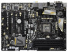
1 64Mb BIOS PANEL1 PLED PWRBTN 1 HDLED RESET RSTBTN PWRBTN 16 17 18 19 34 33 32 31 30 29 28 27 26 25 24 23 22 21 20 1 ATX 12V Power Connector (ATX12V1) 22 64Mb SPI Flash 2 1155-Pin CPU Socket 23 Chassis Fan Connector (CHA_FAN1) 3 Power Fan Connector (PWR_FAN1) 24 Dr. Debug 4 CPU Fan - ASRock Z68 Extreme3 Gen3 | User Manual - Page 14
45 Port 5 Central / Bass (Orange) 6 Rear Speaker (Black) 7 Optical SPDIF Out Port 8 Line In (Light Blue) 14 13 12 11 ** 9 10 11 *** 12 13 14 15 16 Front Speaker (Lime) Microphone (Pink) USB 3.0 Ports (USB45) eSATA3 Connector Clear CMOS TABLE for Audio Output Connection Audio Output Channels - ASRock Z68 Extreme3 Gen3 | User Manual - Page 15
Multi-Streaming function, you need to connect a front panel audio cable to the front panel audio header. After restarting your computer, you will find "Mixer Front Speaker, or select "Realtek HDA Audio 2nd output" to use front panel audio. *** eSATA3 connector supports SATA Gen3 in cable 1M. 15 - ASRock Z68 Extreme3 Gen3 | User Manual - Page 16
Precautions Take note of the following precautions before you install motherboard components or change any motherboard settings. 1. Unplug the power cord from the wall socket before touching any component. 2. To avoid damaging the motherboard components due to static electricity, NEVER place your - ASRock Z68 Extreme3 Gen3 | User Manual - Page 17
Intel 1155-Pin CPU, please follow the steps below. Load Plate Load Lever Contact Array Socket Body 1155-Pin Socket Overview Before you insert the 1155-Pin CPU into the socket, please check if the CPU surface is unclean or if there is any bent pin on the socket motherboard for after service. 17 - ASRock Z68 Extreme3 Gen3 | User Manual - Page 18
key Pin1 Pin1 orientation key notch 1155-Pin CPU alignment key 1155-Pin Socket For proper inserting, please ensure to match the two orientation key notches of the CPU with the two alignment keys of the socket. Step 3-3. Carefully place the CPU into the socket by using a purely vertical motion - ASRock Z68 Extreme3 Gen3 | User Manual - Page 19
2.4 Installation of CPU Fan and Heatsink This motherboard is equipped with 1155-Pin socket that supports Intel 1155-Pin CPU. Please adopt the type of heatsink and cooling fan compliant with Intel 1155Pin CPU to dissipate heat. Before you installed the heatsink, you need to spray thermal interface - ASRock Z68 Extreme3 Gen3 | User Manual - Page 20
Memory Modules (DIMM) This motherboard provides four 240-pin DDR3 (Double Data Rate 3) DIMM slots, and supports Dual Channel Memory Technology. four slots. 1. If you want to install two memory modules, for optimal compatibility and reliability, it is recommended to install them in the slots: DDR3_ - ASRock Z68 Extreme3 Gen3 | User Manual - Page 21
notch on the DIMM matches the break on the slot. The DIMM only fits in one correct orientation. It will cause permanent damage to the motherboard and the DIMM if you force the DIMM into the slot at incorrect orientation. Step 3. Firmly insert the DIMM into the slot until the retaining - ASRock Z68 Extreme3 Gen3 | User Manual - Page 22
a chassis fan to motherboard chassis fan connector (CHA_FAN1, CHA_FAN2 or CHA_FAN3) when using multiple graphics cards for better thermal environment. 4. To run the PCI Express in Gen 3 speed, please must install the Ivy Bridge CPU which supports PCI Express Gen3. If you install the Sandy Bridge CPU - ASRock Z68 Extreme3 Gen3 | User Manual - Page 23
identical Quad SLITM-ready graphics cards that are NVIDIA® certified. 2. Make sure that your graphics card driver supports NVIDIA® SLITM technology (driver version 270.61 and later). Download the driver from NVIDIA website (www.nvidia.com). 3. Make sure that your power supply unit (PSU) can provide - ASRock Z68 Extreme3 Gen3 | User Manual - Page 24
Step3. Align and insert ASRock SLI_Bridge_2S Card to the goldfingers on each graphics card. Make sure ASRock SLI_Bridge_2S Card is firmly in place. ASRock SLI_Bridge_2S Card Step4. Connect a VGA cable or a DVI cable to the monitor connector or the DVI connector of the graphics card that is inserted to - ASRock Z68 Extreme3 Gen3 | User Manual - Page 25
card drivers to your system. After that, you can enable the MultiGraphics Processing Unit (GPU) feature in the NVIDIA® nView system tray utility. Please follow the below procedures to enable the multi-GPU feature. For Windows® XP / XP 64-bit OS: (For SLITM mode only) A. Double-click NVIDIA Settings - ASRock Z68 Extreme3 Gen3 | User Manual - Page 26
and then click NVIDIA Corporation. C. Select NVIDIA Control Panel tab. D. Select Control Panel tab. E. From the pop-up menu, select Set SLI and PhysX configuration. In Set PhysX GPU acceleration item, please select Enabled. In Select an SLI configuration item, please select Enable SLI. And click Apply - ASRock Z68 Extreme3 Gen3 | User Manual - Page 27
Guide This motherboard supports supported with Windows® XP with Service Pack 2 / VistaTM / 7 OS. Quad CrossFireXTM feature are supported with Windows® VistaTM / 7 OS only. Please check AMD website for ATITM CrossFireXTM driver updates AMD graphics card manuals for detailed installation guide. Step 1. - ASRock Z68 Extreme3 Gen3 | User Manual - Page 28
Step 2. Connect two Radeon graphics cards by installing CrossFire Bridge on CrossFire Bridge Interconnects on the top of Radeon graphics cards. (CrossFire Bridge is provided with the graphics card you purchase, not bundled with this motherboard. Please refer to your graphics card vendor for details - ASRock Z68 Extreme3 Gen3 | User Manual - Page 29
for ATITM driver updates. Step 3. Step 4. Step 5. Install the required drivers to your system. For Windows® XP OS: A. AMD recommends Windows® XP Service Pack 2 or higher to be installed (If you have Windows® XP Service Pack 2 or higher installed in your system, there is no need to download it - ASRock Z68 Extreme3 Gen3 | User Manual - Page 30
identification or explanation and to the owners' benefit, without intent to infringe. * For further information of AMD CrossFireXTM technology, please check AMD website for updates and details. 30 - ASRock Z68 Extreme3 Gen3 | User Manual - Page 31
motherboard. This motherboard also provides independent display controllers for DVI-D, D-Sub and HDMI to support dual VGA output so that DVI-D, D-sub and HDMI can drive port HDMI port 2. If you have installed onboard VGA driver from our support CD to your system already, you can freely enjoy the - ASRock Z68 Extreme3 Gen3 | User Manual - Page 32
when the add-on VGA card is inserted to this motherboard. 4. Install the onboard VGA driver and the add-on PCI Express VGA card driver to your system. If you have installed the drivers already, there is no need to install them again. 5. Set up a multi-monitor display. For Windows® XP / XP 64-bit - ASRock Z68 Extreme3 Gen3 | User Manual - Page 33
function is supported on this motherboard. To use HDCP function with this motherboard, you need to adopt the monitor that supports HDCP function as well. Therefore, you can enjoy the superior display quality with high-definition HDCP encryption contents. Please refer to below instruction for more - ASRock Z68 Extreme3 Gen3 | User Manual - Page 34
Installation Guide ASRock Smart Remote is only used for ASRock motherboard with CIR header. Please refer to below procedures for the quick installation and usage of ASRock Smart Remote. Step1. Find the CIR header located next to the USB 2.0 header on ASRock motherboard. USB 2.0 header (9-pin - ASRock Z68 Extreme3 Gen3 | User Manual - Page 35
is compatible with most of the chassis on the market. 3. The Multi-Angle CIR Receiver does not support Hot-Plug function. Please install it before you boot the system. * ASRock Smart Remote is only supported by some of ASRock motherboards. Please refer to ASRock website for the motherboard support - ASRock Z68 Extreme3 Gen3 | User Manual - Page 36
need to clear the CMOS when you just finish updating the BIOS, you must boot up the system first, and then shut it down before you do the clear-CMOS action. Please be noted that the password, date, time, user default profile, 1394 GUID and MAC address will be cleared only if the CMOS battery is removed - ASRock Z68 Extreme3 Gen3 | User Manual - Page 37
: see p.13, No. 15) These four Serial ATAII (SATAII) connectors support SATA data cables for internal storage devices. The current SATAII interface allows up hard disk or the SATAII / SATA3 connector on this motherboard. Either end of the 3.5mm audio cable can be connected to the portable audio - ASRock Z68 Extreme3 Gen3 | User Manual - Page 38
2.0 headers on this motherboard. Each USB 2.0 header can support two USB 2.0 ports. Infrared Module Header (5-pin IR1) (see p.13 No. 33) IRTX +5VSB DUMMY 1 GND IRRX Consumer Infrared Module Header (4-pin CIR1) (see p.13 No. 30) 1 GND IRTX IRRX ATX+5VSB This header supports an optional wireless - ASRock Z68 Extreme3 Gen3 | User Manual - Page 39
is reading or writing data. The front panel design may differ by chassis. A front panel module mainly consists of power switch, reset switch, power LED, hard drive activity LED, speaker and etc. When connecting your chassis front panel module to this header, make sure the wire assignments and the - ASRock Z68 Extreme3 Gen3 | User Manual - Page 40
provides 4-Pin CPU fan (Quiet Fan) support, the 3-Pin CPU fan still can work successfully even without the fan speed control function. If you plan to connect the 3-Pin CPU fan to the CPU fan connector on this motherboard, please connect it to Pin 1-3. Pin 1-3 Connected 3-Pin Fan Installation (3-pin - ASRock Z68 Extreme3 Gen3 | User Manual - Page 41
supply along with Pin 1 and Pin 5. 8 5 Serial port Header (9-pin COM1) (see p.13 No. 31) 4-Pin ATX 12V Power Supply Installation 4 1 This COM1 header supports a serial port module. HDMI_SPDIF Header (2-pin HDMI_SPDIF1) (see p.13 No. 32) HDMI_SPDIF header, providing SPDIF audio output to HDMI - ASRock Z68 Extreme3 Gen3 | User Manual - Page 42
2.13 Smart Switches The motherboard has three smart switches: power switch, reset switch and clear CMOS switch, allowing users to quickly turn on/off or reset the sytem clear the CMOS values. Power Switch (PWRBTN) (see p.13 No. 19) Power Switch is a smart switch, allowing users to quickly turn on/ - ASRock Z68 Extreme3 Gen3 | User Manual - Page 43
2.14 Dr. Debug Dr. Debug is used to provide code information, which makes troubleshooting even easier. Please see the diagrams below for reading the Dr. Debug codes. Status Code 0x00 0x01 0x02 0x03 0x04 0x05 0x06 0x07 0x08 0x09 0x0A 0x0B 0x0C - 0x0D 0x0E 0x0F 0x10 0x11 0x12 0x13 0x14 0x15 0x16 0x17 - ASRock Z68 Extreme3 Gen3 | User Manual - Page 44
fied memory initialization error Memory not installed Invalid CPU type or Speed CPU mismatch CPU self test failed or possible CPU cache error CPU micro-code is not found or micro-code update is failed Internal CPU error reset PPI is not available Reserved for future AMI error codes S3 Resume is - ASRock Z68 Extreme3 Gen3 | User Manual - Page 45
of the South Bridge Runtime Services CPU DXE initialization is started CPU DXE initialization (CPU module specific) CPU DXE initialization (CPU module specific) CPU DXE initialization (CPU module specific) CPU DXE initialization (CPU module specific) PCI host bridge initialization North Bridge DXE - ASRock Z68 Extreme3 Gen3 | User Manual - Page 46
PCI bus hot plug Clean-up of NVRAM Configuration Reset (reset of NVRAM settings) Reserved for future AMI codes OEM BDS initialization codes CPU initialization error North Bridge initialization error South Bridge initialization error Some of the Architectural Protocols are not available PCI resource - ASRock Z68 Extreme3 Gen3 | User Manual - Page 47
motherboard adopts Intel® Z68 chipset that supports Serial ATA3 (SATA3) hard disks and RAID (RAID 0, RAID 1, RAID 10, RAID 5, Intel Rapid Storage and Intel Smart Response Technology) functions. You may install SATA3 hard disks on this motherboard for internal storage devices. This section will guide - ASRock Z68 Extreme3 Gen3 | User Manual - Page 48
and in working condition. 2.18 Hot Plug and Hot Swap Functions for SATA3 HDDs This motherboard supports Hot Plug and Hot Swap functions for SATA3 in RAID / AHCI mode. Intel® Z68 chipset provides hardware support for Advanced Host controller Interface (AHCI), a new programming interface for SATA host - ASRock Z68 Extreme3 Gen3 | User Manual - Page 49
installed into system properly. The latest SATA / SATAII / SATA3 driver is available on our support website: www.asrock.com 4. Make sure to use the SATA power cable & data cable, which are from our motherboard package. 5. Please follow below instructions step by step to reduce the risk of HDD crash - ASRock Z68 Extreme3 Gen3 | User Manual - Page 50
do follow below instruction sequence to process the Hot Plug, improper procedure will cause the SATA / SATAII / SATA3 HDD damage and data loss. Step 1 Please connect SATA power cable 1x4-pin end Step 2 Connect SATA data cable to (White) to the power supply 1x4-pin cable. the motherboard's SATAII - ASRock Z68 Extreme3 Gen3 | User Manual - Page 51
2.20 Driver Installation Guide To install the drivers to your system, please insert the support CD to your optical drive first. Then, the drivers compatible to your system can be auto-detected and listed on the support CD driver page. Please follow the order from up to bottom side to install those - ASRock Z68 Extreme3 Gen3 | User Manual - Page 52
functions, please follow below steps. AHCI mode is not supported under Windows® XP / XP 64-bit OS. Using SATA / SATAII / SATA3 HDDs without NCQ function STEP 1: Set Up UEFI. A. Enter UEFI SETUP UTILITY Advanced screen SATA Configuration. B. Set the option "SATA Mode" to [IDE]. STEP 2: Install Windows - ASRock Z68 Extreme3 Gen3 | User Manual - Page 53
. The UEFI chip on the motherboard stores the UEFI SETUP UTILITY. + , or by pressing the reset button on the system chassis. You software is constantly being updated, the following UEFI setup set up the system time/date information OC Tweaker To set up overclocking features Advanced To set - ASRock Z68 Extreme3 Gen3 | User Manual - Page 54
items + / - To change option for the selected items To bring up the selected screen To display the General Help Screen To load optimal default values for all the settings To save changes and exit the UEFI SETUP UTILITY To jump to the Exit Screen or exit the - ASRock Z68 Extreme3 Gen3 | User Manual - Page 55
your system performance. This option appears only when your CPU supports this function. Load Optimized CPU OC Setting You can use this option to load optimized CPU overclocking setting. Please note that overclocing may cause damage to your CPU and motherboard. It should be done at your own risk and - ASRock Z68 Extreme3 Gen3 | User Manual - Page 56
that enabling this function may reduce CPU voltage and lead to system stability or compatibility issue with some power supplies. Please set this item to [Disable] if above issue occurs. Intel Turbo Boost Technology Use this item to enable or disable Intel Turbo Boost Technology. Turbo Boost allows - ASRock Z68 Extreme3 Gen3 | User Manual - Page 57
default is [Auto]. RAS# Active Time (tRAS) Use this item to change RAS# Active Time (tRAS) Auto/Manual setting. The default is [Auto]. Command Rate (CR) Use this item to change Command Rate (CR) Auto/Manual setting. Min: 1N. Max: 2N. The default is [Auto]. Write Recovery Time (tWR) Use this item to - ASRock Z68 Extreme3 Gen3 | User Manual - Page 58
[Auto]. ODT NOM (CHB) Use this item to change ODT NOM (CHB) Auto/Manual setting. The default is [Auto]. Voltage Control Power Saving Mode Use this to enable or disable Power Saving Mode. The default value is [Disabled]. CPU Core Voltage Use this to select CPU Core Voltage. The default value is [Auto - ASRock Z68 Extreme3 Gen3 | User Manual - Page 59
flash utility. Please be noted that the USB flash drive or hard drive must use FAT32/16/12 file system. If you execute Instant Flash utility, the utility will show the UEFI files and their respective information. Select the proper UEFI file to update your UEFI, and reboot your system after UEFI - ASRock Z68 Extreme3 Gen3 | User Manual - Page 60
(C1). The C1 state is supported through the native processor instructions HLT and MWAIT and requires no hardware support from the chipset. In the C1 power state, the processor maintains the context of the system caches. CPU C3 State Support Use this to enable or disable CPU C3 (ACPI C2) report to - ASRock Z68 Extreme3 Gen3 | User Manual - Page 61
is an enhancement to the IA-32 Intel Architecture. An IA-32 processor with "No Execute (NX) Memory Protection" can prevent data pages from being used by malicious software to execute code. This option will be hidden if the current CPU does not support No-Excute Memory Protection. Local x2APIC Use - ASRock Z68 Extreme3 Gen3 | User Manual - Page 62
Bridge Configuration Low MMIO Align Low MMIO resources align at 64MB/1024MB. The default value is [1024M]. VT-d Use this to enable or disable Intel® VT-d technology (Intel is [PCI Express]. Onboard VGA Share Memory This allows you to set onboard VGA share memory feature. The default value is [Auto]. - ASRock Z68 Extreme3 Gen3 | User Manual - Page 63
Mode]. DVMT (Dynamic Video Memory Technology) is an architecture that offers breakthrough performance for the motherboard through efficient memory utilization. In DVMT mode, the graphics driver allocates memory as needed for running graphics applications and is cooperatively using this memory with - ASRock Z68 Extreme3 Gen3 | User Manual - Page 64
first. Onboard HDMI HD Audio This allows you to enable or disable the "Onboard HDMI HD Audio" feature. ACPI HPET Table Use this item to enable or disable ACPI HPET Table. The default value is [Enabled]. Please set this option to [Enabled] if you plan to use this motherboard to submit Windows® VistaTM - ASRock Z68 Extreme3 Gen3 | User Manual - Page 65
the system is power on. The keyboard LED will also be turned off in S1, S3 and S4 state. The default value is [Auto]. Onboard Debug Port LED Use this to enable or disable onboard debug port LED. The default value is [Auto]. 65 - ASRock Z68 Extreme3 Gen3 | User Manual - Page 66
select [Enhanced]. SATA Controller 1 This item appears only when you set "SATA Mode" to [IDE Mode]. Please select [Compatible] when you install legacy OS. If native OS (Windows® XP / VistaTM / 7) is installed, please select [Enhanced]. Hard Disk S.M.A.R.T. Use this item to enable or disable the - ASRock Z68 Extreme3 Gen3 | User Manual - Page 67
3.4.5 Super IO Configuration Serial Port Use this item to enable or disable the onboard serial port. Serial Port Address Use this item to set the address for the onboard serial port. Configuration options: [3F8 / IRQ4] and [3E8 / IRQ4]. Infrared Port Use this item to enable or disable the - ASRock Z68 Extreme3 Gen3 | User Manual - Page 68
RAM Use this item to select whether to auto-detect or disable the Suspend-toRAM feature. Select [Auto] will enable this feature if the OS supports it. Check Ready Bit Use this item to enable or disable the feature Check Ready Bit. PS/2 Keyboard Power On Use this item to enable - ASRock Z68 Extreme3 Gen3 | User Manual - Page 69
OS and UEFI setup when [Disabled] is selected. If you have USB compatibility issue, it is recommended to select [Disabled] to enter OS. [UEFI Setup Only] - USB devices are allowed to use only under UEFI setup and Windows / Linux OS. Legacy USB 3.0 Support Use this option to enable or disable legacy - ASRock Z68 Extreme3 Gen3 | User Manual - Page 70
CPU temperature, motherboard temperature, CPU fan speed, chassis fan speed, and the critical voltage. CPU Fan 1 & 2 Setting This allows you to set the CPU fan Level 4]. Chassis Fan 3 Setting This allows you to set the chassis fan 3 speed. Configuration options: [Full On] and [Manual Mode]. The default - ASRock Z68 Extreme3 Gen3 | User Manual - Page 71
(0XFFFF) means indefinite waiting. Bootup Num-Lock If this item is set to [On], it will automatically activate the Numeric Lock function after boot- ROMs (Legacy and EFI Compatible), specifies what PCI Option ROM to launch. Configuration options: [Legacy ROM] and [EFI Compatible ROM]. The default vale - ASRock Z68 Extreme3 Gen3 | User Manual - Page 72
3.7 Security Screen In this section, you may set or change the supervisor/user password for the system. For the user password, you may also clear it. 72 - ASRock Z68 Extreme3 Gen3 | User Manual - Page 73
3.8 Exit Screen Save Changes and Exit When you select this option, it will pop-out the following message, "Save configuration changes and exit setup?" Select [OK] to save the changes and exit the UEFI SETUP UTILITY. Discard Changes and Exit When you select this option, it will pop-out the following - ASRock Z68 Extreme3 Gen3 | User Manual - Page 74
XP 64-bit. Because motherboard settings and hardware options vary, use the setup procedures in this chapter for general reference only. Refer to your OS documentation for more information. 4.2 Support CD Information The Support CD that came with the motherboard contains necessary drivers and useful - ASRock Z68 Extreme3 Gen3 | User Manual - Page 75
Than 2TB This motherboard is adopting UEFI BIOS that allows Windows® driver is located in the following path of our support CD: .. \Drivers\Serial ATA For Floppy Disk\Intel\v10.6.0.1002\AMD64 Insert the Windows® optical disk into the optical drive to boot your system, and follow the instruction
-
 1
1 -
 2
2 -
 3
3 -
 4
4 -
 5
5 -
 6
6 -
 7
7 -
8
-
9
-
10
-
11
-
12
-
13
-
14
-
15
-
16
-
17
-
18
-
19
-
20
-
21
-
22
-
23
-
24
-
25
-
26
-
27
-
28
-
29
-
30
-
31
-
32
-
33
-
34
-
35
-
36
-
37
-
38
-
39
-
40
-
41
-
42
-
43
-
44
-
45
-
46
-
47
-
48
-
49
-
50
-
51
-
52
-
53
-
54
-
55
-
56
-
57
-
58
-
59
-
60
-
61
-
62
-
63
-
64
-
65
-
66
-
67
-
68
-
69
-
70
-
71
-
72
-
73
-
74
-
75
 |
 |

1
Z68 Extreme3 Gen3
User Manual
Version 1.0
Published July 2011
Copyright©2011 ASRock INC. All rights reserved.