ASRock Z68 Extreme4 Gen3 Quick Installation Guide
ASRock Z68 Extreme4 Gen3 Manual
 |
View all ASRock Z68 Extreme4 Gen3 manuals
Add to My Manuals
Save this manual to your list of manuals |
ASRock Z68 Extreme4 Gen3 manual content summary:
- ASRock Z68 Extreme4 Gen3 | Quick Installation Guide - Page 1
by ASRock. ASRock assumes no responsibility for any errors or omissions that may appear in this guide. With respect to the contents of this guide, ASRock ASRock Website: http://www.asrock.com Published June 2011 Copyright©2011 ASRock INC. All rights reserved. 1 ASRock Z68 Extreme4 Gen3 Motherboard - ASRock Z68 Extreme4 Gen3 | Quick Installation Guide - Page 2
4a PCIE1 CHA_FAN2 1 CLRCMOS1 ErP/EuP Ready LAN PHY Super I/O Designed in Taipei AUDIO CODEC HD_AUDIO1 1 HDMI_SPDIF1 COM1 1 1 PCIE2 RoHS PCIE3 PCI Express 3.0 PCI1 Z68 Extreme4 Gen3 CMOS Battery PCIE4 XFast USB PCI2 DX10.1 Front USB 3.0 1394a FLOPPY1 PCIE5 IR1 1 FRONT_1394 1 USB6_7 - ASRock Z68 Extreme4 Gen3 | Quick Installation Guide - Page 3
of speaker you use. TABLE for Audio Output Connection Audio Output Channels Front Speaker Rear Speaker Central / Bass Line In or (No. 10) (No. 7) (No. 6) Side Speaker (No. 9) 2 V -- -- -- 4 V V -- -- 6 V V V -- 8 V V V V English 3 ASRock Z68 Extreme4 Gen3 Motherboard - ASRock Z68 Extreme4 Gen3 | Quick Installation Guide - Page 4
"8CH" and then you are allowed to select "Realtek HDA Primary output" to use Rear Speaker, Central/Bass, and Front Speaker, or select "Realtek HDA Audio 2nd output" to use front panel audio. *** eSATA3 connector supports SATA Gen3 in cable 1M. English 4 ASRock Z68 Extreme4 Gen3 Motherboard - ASRock Z68 Extreme4 Gen3 | Quick Installation Guide - Page 5
You... To get better performance in Windows® 7 / 7 64-bit / VistaTM / VistaTM 64bit, it is recommended to set the BIOS option in Storage Configuration to AHCI mode. For the BIOS setup, please refer to the "User Manual" in our support CD for details. 5 ASRock Z68 Extreme4 Gen3 Motherboard English - ASRock Z68 Extreme4 Gen3 | Quick Installation Guide - Page 6
- Supports Intel® HD Graphics Built-in Visuals: Intel® Quick Sync Video, Intel® InTruTM 3D, Intel® Clear Video HD Technology, Intel® HD Graphics 2000/3000, Intel® Advanced Vector Extensions (AVX) - Pixel Shader 4.1, DirectX 11 with Intel® Ivy Bridge CPU, DirectX 10.1 with Intel® Sandy Bridge CPU - ASRock Z68 Extreme4 Gen3 | Quick Installation Guide - Page 7
x RJ-45 LAN Port with LED (ACT/LINK LED and SPEED LED) - 1 x IEEE 1394 Port - 1 x Clear CMOS Switch with LED - HD Audio Jack: Rear Speaker/Central/Bass/Line in/Front Speaker/Microphone (see CAUTION 8) - 2 x SATA3 6.0 Gb/s connectors, support RAID (RAID 0, RAID 1, RAID 10, RAID 5, Intel Rapid Storage - ASRock Z68 Extreme4 Gen3 | Quick Installation Guide - Page 8
- CPU/Chassis/Power FAN connector - 24 pin ATX power connector - 8 pin 12V power connector - SLI/XFire power connector - Front panel audio connector - 3 x USB 2.0 headers (support 6 USB 2.0 ports) - 1 x USB 3.0 header (supports 2 USB 3.0 ports) - 1 x Dr. Debug (7-Segment Debug LED) - 1 x Clear CMOS - ASRock Z68 Extreme4 Gen3 | Quick Installation Guide - Page 9
overclocking tools. Overclocking may affect your system stability, or even cause damage to the components and devices of your system. It should be done at your own risk and expense. We are not responsible for possible damage caused by overclocking. English 9 ASRock Z68 Extreme4 Gen3 Motherboard - ASRock Z68 Extreme4 Gen3 | Quick Installation Guide - Page 10
motherboard supports Dual Channel Memory Technology. Before you implement Dual Channel Memory Technology, make sure to read the installation guide of memory modules on page 16 for proper installation. 3. DDR3 frequency options may depend on the processor. Only K-Series CPU can support DDR3 overclock - ASRock Z68 Extreme4 Gen3 | Quick Installation Guide - Page 11
POST or press key to BIOS setup menu to access ASRock Instant Flash. Just launch this tool and save the new BIOS file to your USB flash drive, floppy disk or hard drive, then you can update your BIOS and advanced media features of Intel® HD graphics. 11 ASRock Z68 Extreme4 Gen3 Motherboard English - ASRock Z68 Extreme4 Gen3 | Quick Installation Guide - Page 12
provides the flexible option to adopt three different CPU cooler types, Socket LGA 775, LGA 1155 and LGA 1156. Please be noticed that not all the 775 and 1156 CPU Fan can be used. 20. EuP, stands for with the power supply manufacturer for more details. 12 ASRock Z68 Extreme4 Gen3 Motherboard English - ASRock Z68 Extreme4 Gen3 | Quick Installation Guide - Page 13
insert the 1155-Pin CPU into the socket, please check if the CPU surface is unclean or if there is any bent pin on the socket. Do not force to insert the CPU into the socket if above situation is found. Otherwise, the CPU will be seriously damaged. English 13 ASRock Z68 Extreme4 Gen3 Motherboard - ASRock Z68 Extreme4 Gen3 | Quick Installation Guide - Page 14
notches. orientation key notch alignment key Pin1 Pin1 orientation key notch 1155-Pin CPU alignment key 1155-Pin Socket For proper inserting, please ensure to match the two orientation key notches of the CPU with the two alignment keys of the socket. 14 ASRock Z68 Extreme4 Gen3 Motherboard - ASRock Z68 Extreme4 Gen3 | Quick Installation Guide - Page 15
. Please be noticed that this motherboard supports Combo Cooler Option (C.C.O.), which provides the flexible option to adopt three different CPU cooler types, Socket LGA 775, LGA 1155 and LGA 1156. The white throughholes are for Socket LGA 1155/1156 CPU fan. 15 ASRock Z68 Extreme4 Gen3 Motherboard - ASRock Z68 Extreme4 Gen3 | Quick Installation Guide - Page 16
to install a DDR or DDR2 memory module into DDR3 slot; otherwise, this motherboard and DIMM may be damaged. 5. Some DDR3 1GB double-sided DIMMs with 16 chips may not work on this motherboard. It is not recommended to install them on this motherboard. English 16 ASRock Z68 Extreme4 Gen3 Motherboard - ASRock Z68 Extreme4 Gen3 | Quick Installation Guide - Page 17
damage to the motherboard and the DIMM if you force the DIMM into the slot at incorrect orientation. Step 3. Firmly insert the DIMM into the slot until the retaining clips at both ends fully snap back in place and the DIMM is properly seated. 17 ASRock Z68 Extreme4 Gen3 Motherboard English - ASRock Z68 Extreme4 Gen3 | Quick Installation Guide - Page 18
a chassis fan to motherboard chassis fan connector (CHA_FAN1, CHA_FAN2 or CHA_FAN3) when using multiple graphics cards for better thermal environment. 5. To run the PCI Express in Gen 3 speed, please must install the Ivy Bridge CPU which supports PCI Express Gen3. If you install the Sandy Bridge CPU - ASRock Z68 Extreme4 Gen3 | Quick Installation Guide - Page 19
be the same.) Insert one graphics card into PCIE2 slot and the other graphics card to PCIE4 slot. Make sure that the cards are properly seated on the slots. Step2. If required, connect the auxiliary power source to the PCI Express graphics cards. 19 ASRock Z68 Extreme4 Gen3 Motherboard English - ASRock Z68 Extreme4 Gen3 | Quick Installation Guide - Page 20
Set SLI and PhysX configuration. In Set PhysX GPU acceleration item, please select Enabled. In Select an SLI configuration item, please select Enable SLI. And click Apply. C. Reboot your system. D. You can freely enjoy the benefit of SLITM feature. 20 ASRock Z68 Extreme4 Gen3 Motherboard English - ASRock Z68 Extreme4 Gen3 | Quick Installation Guide - Page 21
click NVIDIA Corporation. C. Select NVIDIA Control Panel tab. D. Select Control Panel tab. E. From the pop-up menu, select Set SLI and PhysX configuration. In Set PhysX GPU acceleration item, please select the owners' benefit, without intent to infringe. 21 ASRock Z68 Extreme4 Gen3 Motherboard English - ASRock Z68 Extreme4 Gen3 | Quick Installation Guide - Page 22
future, please refer to AMD graphics card manuals for detailed installation guide. Step 1. Insert one Radeon graphics card into PCIE2 slot and the other Radeon graphics card to PCIE4 slot. Make sure that the cards are properly seated on the slots. English 22 ASRock Z68 Extreme4 Gen3 Motherboard - ASRock Z68 Extreme4 Gen3 | Quick Installation Guide - Page 23
the DVI monitor cable to the DVI connector on the Radeon graphics card on PCIE2 slot. (You may use the DVI to D-Sub adapter to convert the DVI connector to D-Sub interface, and then connect the D-Sub monitor cable to the DVI to D-Sub adapter.) English 23 ASRock Z68 Extreme4 Gen3 Motherboard - ASRock Z68 Extreme4 Gen3 | Quick Installation Guide - Page 24
, and use the other CrossFireTM Bridge to connect Radeon graphics cards on PCIE4 and PCIE5 slots. (CrossFireTM Bridge is provided with the graphics card you purchase, not bundled with this motherboard. Please refer to your graphics card vendor for details.) 24 ASRock Z68 Extreme4 Gen3 Motherboard - ASRock Z68 Extreme4 Gen3 | Quick Installation Guide - Page 25
the DVI monitor cable to the DVI connector on the Radeon graphics card on PCIE2 slot. (You may use the DVI to D-Sub adapter to convert the DVI connector to D-Sub interface, and then connect the D-Sub monitor cable to the DVI to D-Sub adapter.) English 25 ASRock Z68 Extreme4 Gen3 Motherboard - ASRock Z68 Extreme4 Gen3 | Quick Installation Guide - Page 26
Control Center". Click "View", select "CrossFireXTM", and then check the item "Enable CrossFireXTM". Select "2 GPUs" and click "Apply" (if you install two Radeon graphics cards). Select "3 GPUs" and click "OK" (if you install three Radeon graphics cards). English 26 ASRock Z68 Extreme4 Gen3 - ASRock Z68 Extreme4 Gen3 | Quick Installation Guide - Page 27
restarting your computer, please confirm whether the option "Enable CrossFireTM" in "ATI Catalyst Control Center" is selected or not; if not, please select it again, and then CrossFireXTM technology, please check AMD website for updates and details. 27 ASRock Z68 Extreme4 Gen3 Motherboard English - ASRock Z68 Extreme4 Gen3 | Quick Installation Guide - Page 28
't installed onboard VGA driver yet, please install onboard VGA driver from our support CD to your system and restart your computer. D-Sub, DVI-D, HDMI and DisplayPort monitors cannot be enabled at the same time. You can only choose two of them. English 28 ASRock Z68 Extreme4 Gen3 Motherboard - ASRock Z68 Extreme4 Gen3 | Quick Installation Guide - Page 29
"Attached", if necessary. F. Set the "Screen Resolution" and "Color Quality" as appropriate for the second monitor. Click "Apply" or "OK" to apply these new values. G. Repeat steps C through E for the diaplay icon identified by the number one to eight. 29 ASRock Z68 Extreme4 Gen3 Motherboard English - ASRock Z68 Extreme4 Gen3 | Quick Installation Guide - Page 30
HDTV set-top-boxes, as well as few entertainment PCs requires a secure connection to a compliant display. Due to the increase in manufacturers employing HDCP in their equipment, it is highly recommended that the HDTV or LCD monitor you purchase is compatible. 30 ASRock Z68 Extreme4 Gen3 Motherboard - ASRock Z68 Extreme4 Gen3 | Quick Installation Guide - Page 31
-Angle CIR Receiver does not support Hot-Plug function. Please install it before you boot the system. * ASRock Smart Remote is only supported by some of ASRock motherboards. Please refer to ASRock website for the motherboard support list: http://www.asrock.com 31 ASRock Z68 Extreme4 Gen3 Motherboard - ASRock Z68 Extreme4 Gen3 | Quick Installation Guide - Page 32
you do the clear-CMOS action. Please be noted that the password, date, time, user default profile, 1394 GUID and MAC address will be cleared only if the CMOS battery is removed. The Clear CMOS Switch has the same function as the Clear CMOS jumper. English 32 ASRock Z68 Extreme4 Gen3 Motherboard - ASRock Z68 Extreme4 Gen3 | Quick Installation Guide - Page 33
(SATA3_M2: see p.2, No. 12) SATA3_0 SATA3_M1 SATA3_1 SATA3_M2 These four Serial ATA3 (SATA3) connectors support SATA data cables for internal storage devices. The current SATA3 interface allows up to 6.0 Gb/s data connector of the power supply. 33 ASRock Z68 Extreme4 Gen3 Motherboard English - ASRock Z68 Extreme4 Gen3 | Quick Installation Guide - Page 34
USB 3.0 ports. This header supports an optional wireless transmitting and receiving infrared module. Consumer Infrared Module Header (4-pin CIR1) (see p.2 No. 31) 1 GND IRTX IRRX ATX+5VSB This header can be used to connect the remote controller receiver. 34 ASRock Z68 Extreme4 Gen3 Motherboard - ASRock Z68 Extreme4 Gen3 | Quick Installation Guide - Page 35
control of audio devices. 1. High Definition Audio supports Jack Sensing, but the panel wire on the chassis must support HDA to function correctly. Please follow the instruction in our manual and chassis manual to is in S3/S4 sleep state or powered off (S5). 35 ASRock Z68 Extreme4 Gen3 Motherboard - ASRock Z68 Extreme4 Gen3 | Quick Installation Guide - Page 36
of power switch, reset switch, power LED, CPU Fan Connectors (4-pin CPU_FAN1) (see p.2 No. 4) FAN_SPEED_CONTROL 4 CPU_FAN_SPEED 3 +12V 2 GND 1 Please connect the CPU fan cable to the connector and match the black wire to the ground pin. English 36 ASRock Z68 Extreme4 Gen3 Motherboard - ASRock Z68 Extreme4 Gen3 | Quick Installation Guide - Page 37
/XFIRE_PWR1) (see p.2 No. 45) SLI/XFIRE_POWER1 It is not necessary to use this connector, but please connect it with a hard disk power connecor when two graphics cards are plugged to this motherboard. English 37 ASRock Z68 Extreme4 Gen3 Motherboard - ASRock Z68 Extreme4 Gen3 | Quick Installation Guide - Page 38
/SSD to the Front HDD screws, and six chassis screws. USB 3.0 Panel with four HDD screws. Step 3 Intall the Front USB 3.0 Panel into the 2.5" drive bay of the chassis. Step 4 Screw the Front USB 3.0 Panel to the drive bay with six chassis screws. English 38 ASRock Z68 Extreme4 Gen3 Motherboard - ASRock Z68 Extreme4 Gen3 | Quick Installation Guide - Page 39
Step 1 Unscrew the two screws from the Front USB 3.0 Step 2 Put the USB 3.0 cable and the rear Panel. USB 3.0 bracket together. Step 3 Screw the two screws into the rear USB 3.0 bracket. Step 4 Put the rear USB 3.0 bracket into the chassis. English 39 ASRock Z68 Extreme4 Gen3 Motherboard - ASRock Z68 Extreme4 Gen3 | Quick Installation Guide - Page 40
) (see p.2 No. 21) RESET Reset Switch is a smart switch, allowing users to quickly reset the system. Clear CMOS Switch (CLRCBTN) (see p.3 No. 15) clr CMOS Clear CMOS Switch is a smart switch, allowing users to quickly clear the CMOS values. English 40 ASRock Z68 Extreme4 Gen3 Motherboard - ASRock Z68 Extreme4 Gen3 | Quick Installation Guide - Page 41
. Cache initialization CPU post-memory initialization. Application Processor(s) (AP) initialization CPU post-memory initialization. Boot Strap Processor (BSP) selection CPU post-memory initialization. System Management Mode (SMM) initialization 41 ASRock Z68 Extreme4 Gen3 Motherboard English - ASRock Z68 Extreme4 Gen3 | Quick Installation Guide - Page 42
firmware image is found Recovery firmware image is loaded Reserved for future AMI progress codes Recovery PPI is not available Recovery capsule is not found Invalid recovery capsule Reserved for future AMI error codes DXE Core is started NVRAM initialization ASRock Z68 Extreme4 Gen3 Motherboard - ASRock Z68 Extreme4 Gen3 | Quick Installation Guide - Page 43
Console input devices connect Super IO Initialization USB initialization is started USB Reset USB Detect USB Enable Reserved for future AMI codes IDE initialization is started IDE Reset IDE Detect IDE Enable SCSI initialization is started SCSI Reset English 43 ASRock Z68 Extreme4 Gen3 Motherboard - ASRock Z68 Extreme4 Gen3 | Quick Installation Guide - Page 44
ROM No Console Output Devices are found No Console Input Devices are found Invalid password Error loading Boot Option (LoadImage returned error) Boot Option is failed (StartImage returned error) Flash update is failed Reset protocol is not available English 44 ASRock Z68 Extreme4 Gen3 Motherboard - ASRock Z68 Extreme4 Gen3 | Quick Installation Guide - Page 45
. B. Set the option "SATA Mode" to [IDE]. (For SATA3_0, SATA3_1 and SATA2_2 to SATA2_5 ports.) Set the option "Marvell SATA3 Operation Mode" to [IDE]. (For SATA3_M1 and SATA3_M2 ports.) STEP 2: Install Windows® XP / XP 64-bit OS on your system. 45 ASRock Z68 Extreme4 Gen3 Motherboard English - ASRock Z68 Extreme4 Gen3 | Quick Installation Guide - Page 46
"SATA Mode" to [AHCI]. (For SATA3_0, SATA3_1 and SATA2_2 to SATA2_5 ports.) Set the option "Marvell SATA3 Operation Mode" to [AHCI]. (For SATA3_M1 and SATA3_M2 ports.) STEP 2: Install Windows® 7 / 7 64-bit / VistaTM / VistaTM 64-bit OS on your system. 46 ASRock Z68 Extreme4 Gen3 Motherboard English - ASRock Z68 Extreme4 Gen3 | Quick Installation Guide - Page 47
your computer. If the Main Menu does not appear automatically, locate and double-click on the file "ASSETUP.EXE" from the BIN folder in the Support CD to display the menus. 47 ASRock Z68 Extreme4 Gen3 Motherboard English - ASRock Z68 Extreme4 Gen3 | Quick Installation Guide - Page 48
Sie bitte unsere Webseite: www.asrock.com/support/index.asp 1.1 Kartoninhalt ASRock Z68 Extreme4 Gen3 Motherboard (ATX-Formfaktor: 30.5 cm x 24.4 cm; 12.0 Zoll x 9.6 Zoll) ASRock Z68 Extreme4 Gen3 Schnellinstallationsanleitung ASRock Z68 Extreme4 Gen3 Support-CD Ein Flachbandkabel für ein 3,5-Zoll - ASRock Z68 Extreme4 Gen3 | Quick Installation Guide - Page 49
4.1, DirectX 11 mit Intel® Ivy Bridge-Prozessor, DirectX 10.1 mit Intel® Sandy Bridge-Prozessor - Maximal gemeinsam genutzter Speicher 1759MB (siehe VORSICHT 5) - Vier VGA-Ausgangsoptionen: D-Sub, DVI-D, HDMI sowie DisplayPort (siehe VORSICHT 6) 49 ASRock Z68 Extreme4 Gen3 Motherboard Deutsch - ASRock Z68 Extreme4 Gen3 | Quick Installation Guide - Page 50
USB 3.0-Anschlüsse - 1 x RJ-45 LAN Port mit LED (ACT/LINK LED und SPEED LED) - 1 x IEEE 1394 Port - 1 x CMOS löschen-Schalter mit LED - HD Audiobuchse: Lautsprecher hinten / Mitte/Bass / Audioeingang / Lautsprecher vorne / Mikrofon (siehe VORSICHT 8) Deutsch 50 ASRock Z68 Extreme4 Gen3 Motherboard - ASRock Z68 Extreme4 Gen3 | Quick Installation Guide - Page 51
Debug-LED mit 7 Segmenten) - 1 x CMOS löschen-Schalter mit LED - 1 x Netzschalter mit LED - 1 x Rücksetzschalter (Reset) mit LED - 64Mb AMI BIOS - AMIs Legal BIOS UEFI mit GUI-Unterstützung - Unterstützung für "Plug and Play" - ACPI 1.1-Weckfunktionen 51 ASRock Z68 Extreme4 Gen3 Motherboard Deutsch - ASRock Z68 Extreme4 Gen3 | Quick Installation Guide - Page 52
äß Ökodesign-Richtlinie (ErP/EuP) (Stromversorgung gemäß Ökodesign-Richtlinie (ErP/EuP) erforderlich) (siehe VORSICHT 20) * Für die ausführliche Produktinformation, besuchen Sie bitte unsere Website: http://www.asrock.com Deutsch 52 ASRock Z68 Extreme4 Gen3 Motherboard - ASRock Z68 Extreme4 Gen3 | Quick Installation Guide - Page 53
können Sie die Hauptsystemdaten einsehen. Die Lüftersteuerung zeigt Ihnen zur Anpassung Lüftergeschwindigkeit und Temperatur an. Bei der Übertaktung können Sie die CPU-Frequenz zur Erzielung optimaler Systemleistung übertakten. OC DNA ermöglicht 53 ASRock Z68 Extreme4 Gen3 Motherboard Deutsch - ASRock Z68 Extreme4 Gen3 | Quick Installation Guide - Page 54
CPU POST-Vorgangs oder durch Drücken der -Taste im BIOS-Setup-Menü Zugang zu ASRock Instant Flash. Sie brauchen dieses Werkzeug einfach nur zu starten und die neue BIOS-Datei auf Ihrem USB RAM ASRock-Website: http:// www.asrock.com/Feature/SmartView/index.asp 54 ASRock Z68 Extreme4 Gen3 Motherboard - ASRock Z68 Extreme4 Gen3 | Quick Installation Guide - Page 55
. 17. Obwohl dieses Motherboard stufenlose Steuerung bietet, wird Overclocking nicht empfohlen. Frequenzen, die verschiedenen CPU-Kühlertypen, Socket LGA 775, LGA 1155 und LGA 1156. Beachten Sie bitte, dass nicht alle 775 und 1156 CPU-Lüfter verwendet 55 ASRock Z68 Extreme4 Gen3 Motherboard Deutsch - ASRock Z68 Extreme4 Gen3 | Quick Installation Guide - Page 56
-Pin Sockel Übersicht Bevor Sie die 1155-Pin CPU in den Sockel sitzen, prüfen Sie bitte, ob die CPU-Oberfläche sauber ist und keine der Kontakte verbogen sind. Setzen Sie die CPU nicht mit Gewalt in den Sockel, dies kann die CPU schwer beschädigen. Deutsch 56 ASRock Z68 Extreme4 Gen3 Motherboard - ASRock Z68 Extreme4 Gen3 | Quick Installation Guide - Page 57
IHS (Integrated Heat Sink - integrierter Kühlkörper) nach oben. Suchen Sie Pin 1 und die zwei Orientierungseinkerbungen. Orientierungskerbe Ausrichtungsmarkierung Pin1 Orientierungskerbe 1155-Pin CPU Ausrichtungsmarkierung 1155-Pin Sockel ASRock Z68 Extreme4 Gen3 Motherboard Pin1 57 Deutsch - ASRock Z68 Extreme4 Gen3 | Quick Installation Guide - Page 58
. Schritt 3-3. Drücken Sie die CPU vorsichtig in vertikaler Richtung in den Sockel. Schritt 3-4. Prüfen Sie, dass die CPU ordnungsgemäß im Sockel sitzt und die . Schritt 4-3. Sichern Sie Ladehebel und Ladeplatte mithilfe des Hebelverschlusses. 58 ASRock Z68 Extreme4 Gen3 Motherboard Deutsch - ASRock Z68 Extreme4 Gen3 | Quick Installation Guide - Page 59
Motherboard die Combo-Kühleroption unterstützt, die eine flexible Möglichkeit zur Aufnahme von drei verschiedenen CPU-Kühlertypen, Socket LGA 775, LGA 1155 und LGA 1156, bietet. Das weiße Durchgangsloch ist für den CPU-Lüfter im Socket LGA 1155/1156 vorgesehen. Deutsch 59 ASRock Z68 Extreme4 Gen3 - ASRock Z68 Extreme4 Gen3 | Quick Installation Guide - Page 60
; andernfalls könnten Motherboard und DIMMs beschädigt werden. 5. Einige doppelseitige 1 GB-DDR3-DIMMs mit 16 Chips funktionieren möglicherweise nicht auf diesem Motherboard. Wir empfehlen, sie nicht auf diesem Motherboard zu installieren. Deutsch 60 ASRock Z68 Extreme4 Gen3 Motherboard - ASRock Z68 Extreme4 Gen3 | Quick Installation Guide - Page 61
die Steckplätze, so dass die Halteklammern an beiden Enden des Moduls einschnappen und das DIMM-Modul fest an Ort und Stelle sitzt. Deutsch 61 ASRock Z68 Extreme4 Gen3 Motherboard - ASRock Z68 Extreme4 Gen3 | Quick Installation Guide - Page 62
ätze am Z68 Extreme4 Gen3 Motherboard. PCI-Slots: PCI-Slots werden zur Installation von Erweiterungskarten mit dem 32bit PCI-Interface genutzt. PCI Express-Slots: PCIE1 / PCIE3 (PCIE 2.0 x1-Steckplatz) wird für PCI Express-Karten mit x1 Lane-Breite-Karten verwendet, z.B. Gigabit LAN-Karte, SATA2 - ASRock Z68 Extreme4 Gen3 | Quick Installation Guide - Page 63
Derzeit wird die CrossFireXTM-Funktion von den Betriebssystemen Windows® XP mit Service Pack 2 / VistaTM / 7 unterstützt. Die 3-Way ATITM CrossFireXTM-Treiber-Updates gibt. Beachten Sie den detailliert erklärten Installationsablauf auf Seite 22. Deutsch 63 ASRock Z68 Extreme4 Gen3 Motherboard - ASRock Z68 Extreme4 Gen3 | Quick Installation Guide - Page 64
IRTX IRRX ATX+5VSB Schritt 3. Installieren Sie den Mehrwinkel-CIREmpfänger am vorderen USB-Port. ASRock Smart Remote wird nur von einigen ASRock-Motherboards unterstützt. Eine Liste dieser Motherboards finden Sie auf der ASRock-Webseite: http://www.asrock.com 64 ASRock Z68 Extreme4 Gen3 Motherboard - ASRock Z68 Extreme4 Gen3 | Quick Installation Guide - Page 65
herunter. Bitte beachten Sie, dass Kennwort, Datum, Uhrzeit, benutzerdefiniertes Profil, 1394 GUID und MAC-Adresse nur gelöscht werden, wenn die CMOS-Batterie entfernt wird. Der CMOS löschen-Schalter hat dieselbe Funktion wie der CMOS löschen-Jumper. Deutsch 65 ASRock Z68 Extreme4 Gen3 Motherboard - ASRock Z68 Extreme4 Gen3 | Quick Installation Guide - Page 66
und Anschlüsse. Wenn Sie Jumperkappen auf Header und Anschlüsse setzen, wird das Motherboard unreparierbar beschädigt! Anschluss für das Floppy-Laufwerk (33-Pin FLOPPY1) (siehe S.2 Verbindungsstück auf dieser Hauptplatine angeschlossen werden. Deutsch 66 ASRock Z68 Extreme4 Gen3 Motherboard - ASRock Z68 Extreme4 Gen3 | Quick Installation Guide - Page 67
zwei Standard-USB 3.0-Ports am E/A-Panel befindet sich ein USB 3.0Header an diesem Motherboard. Dieser USB 3.0- 1 Header kann zwei USB 3.0- Vbus IntA_P1_SSRX- Ports unterstützen. IntA_P1_SSRX+ GND IntA_P1_SSTXIntA_P1_SSTX+ GND IntA_P1_D- IntA_P1_D+ ID 67 ASRock Z68 Extreme4 Gen3 Motherboard - ASRock Z68 Extreme4 Gen3 | Quick Installation Guide - Page 68
glicht Ihnen eine bequeme Anschlussmöglichkeit und Kontrolle über Audio-Geräte. 1. High Definition Audio unterstützt Jack Sensing (automatische Erkennung falsch angeschlossener Ger 24) Dieser Header unterstützt mehrere Funktion der Systemvorderseite. Deutsch 68 ASRock Z68 Extreme4 Gen3 Motherboard - ASRock Z68 Extreme4 Gen3 | Quick Installation Guide - Page 69
des Ein-/Ausschalters ausgeschaltet werden können soll. RESET (Reset-Taste): Zum Anschließen der Reset-Taste an der Frontblende des Gehäuses. Mit der Reset-Taste können Sie den Computer im Falle eines S4- oder S5-Zustand (ausgeschaltet) leuchtet die LED nicht. 69 ASRock Z68 Extreme4 Gen3 Motherboard - ASRock Z68 Extreme4 Gen3 | Quick Installation Guide - Page 70
Motherboard einen vierpoligen CPU-Lüfteranschluss (Quiet Fan) bietet, können auch CPU ATX-Netzteil verwendet werden. Um ein 20-pol. ATX-Netzteil zu verwenden, stecken Sie den Stecker mit Pin 1 und Pin 13 ein. Installation eines 20-pol. ATX-Netzteils 1 13 70 ASRock Z68 Extreme4 Gen3 Motherboard - ASRock Z68 Extreme4 Gen3 | Quick Installation Guide - Page 71
Installation der 4-Pin ATX 12V Energieversorgung 4 1394 Header (FRONT_1394) auf dieser Hauptplatine. Dieser IEEE-1394 Header kann einen IEEE-1394 Port unterstützen. Dieser COM-AnschlussHeader wird verwendet, um ein COM-Anschlussmodul zu unterstützen. Deutsch 71 ASRock Z68 Extreme4 Gen3 Motherboard - ASRock Z68 Extreme4 Gen3 | Quick Installation Guide - Page 72
Sie die USB 3.0-Frontblende mit sechs Gehäuseschrauben am Festplatteneinschub. Schritt 5 Schließen Sie das Kabel der USB 3.0-Frontblende am USB 3.0-Header (USB3_12_13) am Motherboard an. Schritt 6 Die USB 3.0-Frontblende ist nun einsatzbereit. Deutsch 72 ASRock Z68 Extreme4 Gen3 Motherboard - ASRock Z68 Extreme4 Gen3 | Quick Installation Guide - Page 73
ein Schnellschalter, mit dem Benutzer das System schnell zurücksetzen können. CMOS löschen-Schalter (CLRCBTN) (siehe S.3 - No. 15) clr CMOS Der CMOS löschen-Schalter ist ein Schnellschalter, mit dem Benutzer die CMOS-Werte schnell löschen können. 73 ASRock Z68 Extreme4 Gen3 Motherboard Deutsch - ASRock Z68 Extreme4 Gen3 | Quick Installation Guide - Page 74
auf der Unterstützungs-CD finden: ..\ RAID Installation Guide 2.14 Windows® 7 / 7 64-Bit / VistaTM / VistaTM 64-Bit / XP / XP 64-Bit ohne RAID-Funktionalität installieren Wenn Sie Windows® 7 / Operation Mode" auf [IDE]. (Für SATA3_M1 zu SATA3_M2.) 74 ASRock Z68 Extreme4 Gen3 Motherboard Deutsch - ASRock Z68 Extreme4 Gen3 | Quick Installation Guide - Page 75
RAID-Funktionalität auf Ihren SATA / SATAII / SATA3-Festplatten installieren, gehen Sie bitte wie folgt vor. Verwendung von SATA / SATAII / SATA3-Festplatten ohne NCQ-Funktionen SCHRITT 1: UEFI einrichten. A. Rufen Sie das UEFI SETUP in Ihrem System. 75 ASRock Z68 Extreme4 Gen3 Motherboard Deutsch - ASRock Z68 Extreme4 Gen3 | Quick Installation Guide - Page 76
der Support-CD, um die Menüs aufzurufen. Das Setup-Programm soll es Ihnen so leicht wie möglich machen. Es ist menügesteuert, d.h. Sie können in den verschiedenen Untermenüs Ihre Auswahl treffen und die Programme werden dann automatisch installiert. 76 ASRock Z68 Extreme4 Gen3 Motherboard Deutsch - ASRock Z68 Extreme4 Gen3 | Quick Installation Guide - Page 77
sous Windows® 7 / 7 64 bits / VistaTM / VistaTM 64 bits, il est recommandé de paramétrer l'option BIOS dans Configuration de stockage en mode AHCI. Pour plus de détails sur l'installation BIOS, référez-vous au "Mode d'emploi" sur votre CD de support. 77 ASRock Z68 Extreme4 Gen3 Motherboard Français - ASRock Z68 Extreme4 Gen3 | Quick Installation Guide - Page 78
Intel® HD Graphics 2000/3000, Intel® Advanced Vector Extensions (AVX) - Pixel Shader 4.1, DirectX 11 avec CPU Intel® Ivy Bridge, DirectX 10.1 avec CPU Intel® Sandy Bridge - nuanceur de pixels 4.1, DirectX 10.1 - mémoire partagée max 1759MB (voir ATTENTION 5) 78 ASRock Z68 Extreme4 Gen3 Motherboard - ASRock Z68 Extreme4 Gen3 | Quick Installation Guide - Page 79
de sortie optique SPDIF - 4 x ports USB 2.0 par défaut - 1 x Connecteur eSATA3 - 2 x ports USB 3.0 par défaut - 1 x port LAN RJ-45 avec LED (ACT/LED CLIGNOTANTE et LED VITESSE) - 1 x port IEEE 1394 - 1 x interrupteur d'effacement du CMOS avec LED 79 ASRock Z68 Extreme4 Gen3 Motherboard Français - ASRock Z68 Extreme4 Gen3 | Quick Installation Guide - Page 80
prendre en charge 6 ports USB 2.0 supplémentaires) - 1 x En-tête USB 3.0 (prendre en charge 2 ports USB 3.0 supplémentaires) - 1 x Dr. Debug (LED de débogage à 7 segments) - 1 x interrupteur d'effacement du CMOS avec LED - 1 x interrupteur d'alimentation avec LED ASRock Z68 Extreme4 Gen3 Motherboard - ASRock Z68 Extreme4 Gen3 | Quick Installation Guide - Page 81
, selon la température de l'unité centrale) - Commande de ventilateur CPU/boîtier à plusieurs vitesses - Monitoring de la tension: +12V, +5V, +3.3V, Vcore - Microsoft® Windows® 7 / 7 64-bit / VistaTM / VistaTM 64-bit / XP / XP 64-bit - FCC, CE, WHQL 81 ASRock Z68 Extreme4 Gen3 Motherboard Français - ASRock Z68 Extreme4 Gen3 | Quick Installation Guide - Page 82
effectuer la bonne connexion. 9. ASRock Extreme Tuning Utility (AXTU) est un utilitaire tout-en-un qui permet de régler précisément différentes fonctions du système, via une interface facile à utiliser, incluant Moniteur de périphériques, Contrôle du 82 ASRock Z68 Extreme4 Gen3 Motherboard Français - ASRock Z68 Extreme4 Gen3 | Quick Installation Guide - Page 83
Overclocking, vous pouvez overclocker la fréquence du CPU POST ou premir a tecla para exibir o menu de configuração do BIOS para aceder ao ASRock Instant Flash. Execute esta ferramenta para guardar o novo ficheiro de BIOS numa unidade flash USB la RAM ( ASRock Z68 Extreme4 Gen3 Motherboard Français - ASRock Z68 Extreme4 Gen3 | Quick Installation Guide - Page 84
Intel® HD. 16. La Technologie Lecture Marche/Arrêt ASRock permet aux utilisateurs d'expériencer l'audio incroyable à partir d'appareils audio sde CPU, les sockets LGA 775, LGA 1155 et LGA 1156. Veuillez noter que tous les ventilateurs de CPU 775 ASRock Z68 Extreme4 Gen3 Motherboard Français - ASRock Z68 Extreme4 Gen3 | Quick Installation Guide - Page 85
4. A chaque désinstallation de composant, placez-le sur un support antistatique ou dans son sachet d'origine. 5. Lorsque vous placez les la carte mère. 2.1 Installation du CPU Pour l'installation du processeur Intel 1155 broches, veuillez suivre la procédure ASRock Z68 Extreme4 Gen3 Motherboard - ASRock Z68 Extreme4 Gen3 | Quick Installation Guide - Page 86
tre mis en place si vous renvoyez la carte mère pour service après vente. Etape 3. Insérez le processeur 1155 broches : Etape 3-1. Tenez le processeur par ses bords là 1 broche 1 Encoche d'orientation Détrompeur Socket 1155 broches Processeur 1155 broches 86 ASRock Z68 Extreme4 Gen3 Motherboard - ASRock Z68 Extreme4 Gen3 | Quick Installation Guide - Page 87
reporter aux manuels d'instructions de votre ventilateur 1155 broches. Etape 1. Appliquez le matériau d'interface thermique au centre de IHS sur la surface du socket. (Appliquez le matériau d'interface thermique) Apply Thermal Interface Material Français 87 ASRock Z68 Extreme4 Gen3 Motherboard - ASRock Z68 Extreme4 Gen3 | Quick Installation Guide - Page 88
le socket. Vérifiez que les câbles du ventilateur sont Fan cables on side closest to MB header orientés vers le CPU, les sockets LGA 775, LGA 1155 et LGA 1156. Les trous traversant blancs sont pour le ventilateur de CPU au socket LGA 1155/1156. Français 88 ASRock Z68 Extreme4 Gen3 Motherboard - ASRock Z68 Extreme4 Gen3 | Quick Installation Guide - Page 89
des modules m émoire [DIMM] La carte mère Z68 Extreme4 Gen3 dispose de quatre emplacements DIMM DDR3 (Double Data Rate 3) de 240-broches, et supporte la Technologie de Mémoire à Canal Double. Pour carte mère et les DIMM pourraient être endommagés. Français 89 ASRock Z68 Extreme4 Gen3 Motherboard - ASRock Z68 Extreme4 Gen3 | Quick Installation Guide - Page 90
jusqu'à ce que les clips de maintien situés aux deux extrémités se ferment complètement et que le module DIMM soit inséré correctement. 90 ASRock Z68 Extreme4 Gen3 Motherboard - ASRock Z68 Extreme4 Gen3 | Quick Installation Guide - Page 91
PCI Express à la vitesse Gen 3, veuillez installer le CPU Ivy Bridge qui supporte PCI Express Gen3. Si vous installez le CPU Sandy Bridge, PCI Express ne fonctionnera qu'à la vitesse de PCI Express . Etape 4. Fixez la carte sur le châssis à l'aide d'une vis. 91 ASRock Z68 Extreme4 Gen3 Motherboard - ASRock Z68 Extreme4 Gen3 | Quick Installation Guide - Page 92
et Quad CrossFireXTM est pris en charge par Windows® VistaTM / 7 uniquement. Veuillez consulter le site d'AMD pour les mises à jour de driver ATITM CrossFireXTM. Veuillez suivre les instructions d'installation de la page 22 pour plus de détails. 92 ASRock Z68 Extreme4 Gen3 Motherboard Français - ASRock Z68 Extreme4 Gen3 | Quick Installation Guide - Page 93
. Veuillez l'installer avant de démarrer le système. * La télécommande ASRock n'est prise en charge que par certaines cartes mères of ASRock. Pour la liste des cartes mères prises en charge, veuillez vous reporter au site web ASRock : http://www.asrock.com 93 ASRock Z68 Extreme4 Gen3 Motherboard - ASRock Z68 Extreme4 Gen3 | Quick Installation Guide - Page 94
connecteurs causera à la carte mère des dommages irréversibles! Connecteur du lecteur de disquette (FLOPPY1 br. 33) (voir p.2 No. 34) 94 le côté avec fil rouge côté Broche1 ASRock Z68 Extreme4 Gen3 Motherboard - ASRock Z68 Extreme4 Gen3 | Quick Installation Guide - Page 95
connecteur d'alimentation sur chaque unité. Connectez ensuite l'extrémité blanche du cordon d'alimentation SATA sur le connecteur d'alimentation de l'unité d'alimentation électrique. Français 95 ASRock Z68 Extreme4 Gen3 Motherboard - ASRock Z68 Extreme4 Gen3 | Quick Installation Guide - Page 96
ports USB 3.0 par défaut sur le panneau E/S, il y a une barrette USB 3.0 sur la carte mère. Cette barrette USB 3.0 peut prendre en charge deux ports USB 3.0. Cet en-tête supporte un module infrarouge optionnel de transfert et de réception sans fil. Français 96 ASRock Z68 Extreme4 Gen3 Motherboard - ASRock Z68 Extreme4 Gen3 | Quick Installation Guide - Page 97
Veuillez suivre les instructions dans notre manuel et le manuel de châssis afin installer votre système. 2. Si vous utilisez le panneau audio AC'97, installez-le sur l'adaptateur audio du panneau avant et négatives avant de connecter les câbles. Français 97 ASRock Z68 Extreme4 Gen3 Motherboard - ASRock Z68 Extreme4 Gen3 | Quick Installation Guide - Page 98
gurer la façon de mettre votre système hors tension avec l'interrupteur d'alimentation. RESET (Interrupteur de réinitialisation): Connectez ici le connecteur de réinitialisation sur le panneau avant du correspondre le fil noir à la broche de terre. Français 98 ASRock Z68 Extreme4 Gen3 Motherboard - ASRock Z68 Extreme4 Gen3 | Quick Installation Guide - Page 99
offre un support de (Ventilateur silencieux ventilateur de CPU à 4 broches , le ventilateur de CPU à 3 ATX 1 13 Connecteur ATX 12V (ATX12V1 br.8) (voir p.2 No. 1) 8 5 4 1 Veuillez connecter une unité d'alimentation électrique ATX 12V sur ce connecteur. 99 ASRock Z68 Extreme4 Gen3 Motherboard - ASRock Z68 Extreme4 Gen3 | Quick Installation Guide - Page 100
, fournissant une sortie audio SPDIF vers la carte VGA HDMI, et permettant au système de se connecter au un téléviseur numérique HDMI /un projecteur / un périphérique LCD. Veuillez brancher le connecteur HDMI_SPDIF de la carte VGA HDMI sur ce connecteur. 100 ASRock Z68 Extreme4 Gen3 Motherboard - ASRock Z68 Extreme4 Gen3 | Quick Installation Guide - Page 101
ère USB 3.0 Étape 1 Dévissez les deux vis du panneau avant USB 3.0. Étape 2 Assemblez le câble USB 3.0 et le support arrière USB 3.0. Étape 3 Vissez les deux vis dans le support arrière USB 3.0. Étape 4 Placez le support arrière USB 3.0 dans le châssis. 101 ASRock Z68 Extreme4 Gen3 Motherboard - ASRock Z68 Extreme4 Gen3 | Quick Installation Guide - Page 102
(voir p.2 No. 21) RESET Interrupteur d'effacement de CMOS (CLRCBTN) (voir p.3 No. 15) clr CMOS L'interrupteur d'alimentation est un CMOS est un interrupteur rapide qui permet à l'utilisateur d'effacer rapidement les valeurs du CMOS. Français 102 ASRock Z68 Extreme4 Gen3 Motherboard - ASRock Z68 Extreme4 Gen3 | Quick Installation Guide - Page 103
à UEFI SETUP UTILITY (Utilitaire de configuration UEFI) → écran Avancé → Configuration Storage. B. Réglez «SATA Mode « sur [IDE]. (Pour SATA3_0, SATA3_1 et SATA2_2 à SATA2_5.) Réglez «Marvell SATA3 Operation Mode « sur [IDE]. (Pour SATA3_M1 à SATA3_M2.) 103 ASRock Z68 Extreme4 Gen3 Motherboard Fran - ASRock Z68 Extreme4 Gen3 | Quick Installation Guide - Page 104
sur vos disques durs SATA / SATAII / SATA3 sans les fonctions RAID, veuillez suivre la procédure ci-dessous. Utilisation des disques durs ETAPE 1 : Configurez le UEFI. A. Accédez à UEFI SETUP UTILITY (Utilitaire de configuration UEFI) → écran Avancé → Con ASRock Z68 Extreme4 Gen3 Motherboard Français - ASRock Z68 Extreme4 Gen3 | Quick Installation Guide - Page 105
n'apparaît pas automatiquement, localisez dans le CD technique le fichier "ASSETUP.EXE" dans le dossier BIN et doublecliquez dessus pour afficher les menus. 105 ASRock Z68 Extreme4 Gen3 Motherboard Français - ASRock Z68 Extreme4 Gen3 | Quick Installation Guide - Page 106
/ VistaTM 64-bit, si consiglia di impostare l'opzione BIOS in Storage Configuration (Configurazione di archiviazione) sulla modalità AHCI. Per l'impostazione BIOS, fare riferimento a "User Manual" (Manuale dell'utente) nel CD di supporto per dettagli. ASRock Z68 Extreme4 Gen3 Motherboard Italiano - ASRock Z68 Extreme4 Gen3 | Quick Installation Guide - Page 107
- Supporta Intel® HD Graphics Built-in Visuals: Intel® Quick Sync Video, Intel® InTruTM 3D, Intel® Clear Video HD Technology, Intel® HD Graphics 2000/3000, Intel® Advanced Vector Extensions (AVX) - Pixel Shader 4.1, DirectX 11 con CPU Intel® Ivy Bridge, DirectX 10.1 con CPU Intel® Sandy Bridge - ASRock Z68 Extreme4 Gen3 | Quick Installation Guide - Page 108
RAID 10, RAID 5, Intel Rapid Storage e tecnologia Intel Smart Response) e delle funzioni NCQ, AHCI e "Hot Plug" - 2 x Connettori SATA3 6,0Gb/s SE9120 Marvell, supporto delle funzioni NCQ, AHCI e "Hot Plug" (il connettore SATA3_M2 è condiviso con la porta eSATA3) ASRock Z68 Extreme4 Gen3 Motherboard - ASRock Z68 Extreme4 Gen3 | Quick Installation Guide - Page 109
6.5 Trial, Suite software ASRock (Suite CyberLink DVD OEM e Versione demo; Suite multimediale ASRock MAGIX - OEM) - ASRock Extreme Tuning Utility (AXTU) (vedi ATTENZIONE 9) - ASRock Instant Boot - ASRock Instant Flash (vedi ATTENZIONE 10) 109 ASRock Z68 Extreme4 Gen3 Motherboard Italiano - ASRock Z68 Extreme4 Gen3 | Quick Installation Guide - Page 110
non possiamo essere ritenuti responsabili per possibili danni provocati dall'overclocking. Italiano 110 ATTENZIONE! 1. Per il settaggio della "Tecnologia Hyper-Threading", per favore controllare pagina 66 del Manuale dell'utente all'interno del CD di supporto. ASRock Z68 Extreme4 Gen3 Motherboard - ASRock Z68 Extreme4 Gen3 | Quick Installation Guide - Page 111
il tasto durante il POST, oppure il tasto nel menu BIOS per accedere ad ASRock Instant Flash. Avviare questo strumento e salvare il nuovo file BIOS nell'unità Flash USB, dischetto (disco floppy) o disco rigido; poi si può aggiornare il ASRock Z68 Extreme4 Gen3 Motherboard 111 Italiano - ASRock Z68 Extreme4 Gen3 | Quick Installation Guide - Page 112
ù comodo. 17. Anche se questa motherboard offre il controllo stepless, non si consiglia di effettuare l'overclocking. Frequenze del bus del processore diverse da quelle raccomandate possono causare instabilità al sistema o danni al processore e alla scheda madre. ASRock Z68 Extreme4 Gen3 Motherboard - ASRock Z68 Extreme4 Gen3 | Quick Installation Guide - Page 113
processore e il dissipatore quando si installa il sistema. 19. L'opzione C.C.O. (Combo Cooler Option) fornisce la flessibilità di impiegare tre tipi diversi di dispersori di calore CPU, Socket LGA 775, LGA 1155 e LGA di danneggiare la scheda madre. ASRock Z68 Extreme4 Gen3 Motherboard 113 Italiano - ASRock Z68 Extreme4 Gen3 | Quick Installation Guide - Page 114
la CPU 1155-Pin: Fase 3-1. Tenere la CPU dai bordi segnati con linee nere. Fase 3-2. Orientare il pacchetto con l'IHS (Integrated Heat Sink: dispersore di calore integrato) verso l'alto. Individuare il Pin1 ed i due dentelli chiave d'orientamento. 114 ASRock Z68 Extreme4 Gen3 Motherboard Linea - ASRock Z68 Extreme4 Gen3 | Quick Installation Guide - Page 115
Dente di orientamento CPU da 1155-Pin Pin1 Tacca di allineamento Socket da 1155-Pin Per il corretto inserimento, verificare di far combaciare i due denti di allineamento della CPU con le due della linguetta di ritenzione della leva di carico. Italiano 115 ASRock Z68 Extreme4 Gen3 Motherboard - ASRock Z68 Extreme4 Gen3 | Quick Installation Guide - Page 116
della ventola della CPU presente sulla scheda madre (CPU_ (Cavi della ventola sul lato più vicino all'header della MB) Fan cables on side closest CPU, Socket LGA 775, LGA 1155 e LGA 1156. I fori di colore bianco sono per la ventola CPU Socket LGA 1155/1156. 116 ASRock Z68 Extreme4 Gen3 Motherboard - ASRock Z68 Extreme4 Gen3 | Quick Installation Guide - Page 117
moduli di memoria, è impossibile attivare la tecnologia Dual Channel Memory. 3. Se una coppia di moduli di memoria NON è installata chip potrebbero non funzionare su questa scheda madre. Non se ne raccomanda l'installazione su questa scheda madre. Italiano 117 ASRock Z68 Extreme4 Gen3 Motherboard - ASRock Z68 Extreme4 Gen3 | Quick Installation Guide - Page 118
nello slot fino a far scattare completamente in posizione i fermagli di ritegno alle due estremità e fino ad installare correttamente la DIMM nella sua sede. Italiano 118 ASRock Z68 Extreme4 Gen3 Motherboard - ASRock Z68 Extreme4 Gen3 | Quick Installation Guide - Page 119
Express alla velocità Gen 3, bisogna installare la CPU Ivy Bridge che supporta PCI Express Gen3. Se si installa la CPU Sandy Bridge, PCI Express girerà soltanto alla velocità PCI Express nello slot. Step 4. Agganciare la scheda allo chassis con le viti. 119 ASRock Z68 Extreme4 Gen3 Motherboard - ASRock Z68 Extreme4 Gen3 | Quick Installation Guide - Page 120
i mezzi più vantaggiosi possibile per combinare più GPU (Graphics Processing Unit) ad altre prestazioni in un singolo PC. Combinando aggiornamenti dei driver ATITM CrossFireXTM. Attenersi alle procedure d'installazione, a pagina 22, per i dettagli. 120 ASRock Z68 Extreme4 Gen3 Motherboard Italiano - ASRock Z68 Extreme4 Gen3 | Quick Installation Guide - Page 121
GND IRTX IRRX ATX+5VSB Installare il ricevitore CIR multiangolazione sulla porta USB frontale. Se ASRock Smart Remote è supportato solo da alcune schede madre ASRock. Fare riferimento al sito ASRock per l'elenco delle schede madre supportare: http://www.asrock.com ASRock Z68 Extreme4 Gen3 Motherboard - ASRock Z68 Extreme4 Gen3 | Quick Installation Guide - Page 122
della CMOS. Notare che password, data, ore, profilo utente predefinito, 1394 GUID e indirizzo MAC saranno cancellati solo se è rimossa la batteria della CMOS. L'interruttore Clear CMOS (Cancella CMOS) ha la stessa funzione del jumper Clear CMOS. Italiano 122 ASRock Z68 Extreme4 Gen3 Motherboard - ASRock Z68 Extreme4 Gen3 | Quick Installation Guide - Page 123
à del cavo di dati SATA può essere collegata al disco rigido SATA / SATAII / SATA3 o al connettore di SATAII / SATA3 su questa cartolina base. Italiano 123 ASRock Z68 Extreme4 Gen3 Motherboard - ASRock Z68 Extreme4 Gen3 | Quick Installation Guide - Page 124
all'ailmentazione dei dischi SATA Connettere al gruppo di alimentazione Cavo audio da 3,5 mm (Opzionale) Collegare l'estremità nera de cavo USB 3.0 standard del pannello I/O, questa scheda madre è dotata di un header USB 3.0 che supporta due porte USB 3.0. 124 ASRock Z68 Extreme4 Gen3 Motherboard - ASRock Z68 Extreme4 Gen3 | Quick Installation Guide - Page 125
istruzioni del nostro manuale e del manuale del telaio per installare il sistema. 2. Se si utilizza un pannello audio AC'97, installarlo nell'intestazione audio del pannello anteriore, accomoda diverse funzioni di sistema pannello frontale. Italiano 125 ASRock Z68 Extreme4 Gen3 Motherboard - ASRock Z68 Extreme4 Gen3 | Quick Installation Guide - Page 126
d'alimentazione si può configurare il modo in cui si spegne il sistema. RESET (interruttore di ripristino): Va collegato all'interruttore di ripristino del pannello frontale del telaio stato S1. Il LED è spento in stato S3/S4 o S5 (spegnimento). Italiano 126 ASRock Z68 Extreme4 Gen3 Motherboard - ASRock Z68 Extreme4 Gen3 | Quick Installation Guide - Page 127
12 connettore elettrico ATX a 24 pin, ma può funzionare lo stesso se si adotta un alimentatore ATX a 20 pin. Per usare l'alimentatore ATX a 20 pin, collegare l'alimentatore con il Pin 1 e il Pin 13. Installazione dell'alimentatore ATX a 20 pin 1 ASRock Z68 Extreme4 Gen3 Motherboard 24 13 127 - ASRock Z68 Extreme4 Gen3 | Quick Installation Guide - Page 128
(vedi p.2 Nr. 37) 1 GND SPDIFOUT Header HDMI_SPDIF, con uscita audio SPDIF su scheda HDMI VGA, consente al sistema di collegare dispositivi per TV digitale HDMI/proiettori/ LCD . Collegare il connettore HDMI_SPDIF della scheda VGA HDMI a questo header. 128 ASRock Z68 Extreme4 Gen3 Motherboard - ASRock Z68 Extreme4 Gen3 | Quick Installation Guide - Page 129
1 Svitare le due viti dal pannello USB 3.0 anteriore. Punto 2 Collegare il cavo USB 3.0 e il supporto USB 3.0 posteriore. Punto 3 Avvitare le due viti nel supporto USB 3.0 Punto 4 Inserire il supporto USB 3.0 posteriore. posteriore nel telaio. Italiano 129 ASRock Z68 Extreme4 Gen3 Motherboard - ASRock Z68 Extreme4 Gen3 | Quick Installation Guide - Page 130
il sistema. L'interruttore di reset è un interruttore rapido che consente agli utenti di resettare rapidamente il sistema. L'interruttore di pulizia CMOS è un interruttore rapido che consente agli utenti di cancellare velocemente i valori CMOS. Italiano 130 ASRock Z68 Extreme4 Gen3 Motherboard - ASRock Z68 Extreme4 Gen3 | Quick Installation Guide - Page 131
driver compatibili con il sistema vengono rilevati automaticamente ed elencati nella pagina del driver del CD in dotazione. Per l'installazione dei driver relative procedure: ...\ RAID Installation Guide (Guida all'installazione RAID) 2.14 Installazione ASRock Z68 Extreme4 Gen3 Motherboard Italiano - ASRock Z68 Extreme4 Gen3 | Quick Installation Guide - Page 132
unità disco rigido SATA / SATAII / SATA3 senza funzioni RAID, seguire le istruzioni esposte di seguito. Utilizzo dei dischi rigidi Passo 1: Configurare il UEFI. A. Entrare in UEFI SETUP UTILITY (UTILITÀ DI CONFIGURAZIONE DEL UEFI) → Advanced sistema. 132 ASRock Z68 Extreme4 Gen3 Motherboard Italiano - ASRock Z68 Extreme4 Gen3 | Quick Installation Guide - Page 133
BIOS Setup dopo il POST, riavvia il sistema premendo + + , o premi il tasto di reset sullo chassis del sistema. Per informazioni più dettagliate circa il Setup del BIOS, fare riferimento al Manuale volte per visualizzare i menù. 133 ASRock Z68 Extreme4 Gen3 Motherboard Italiano - ASRock Z68 Extreme4 Gen3 | Quick Installation Guide - Page 134
/ VistaTM 64 bits, es recomendable establecer la opción del BIOS de la configuración de almacenamiento en el modo AHCI. Para obtener detalles sobre la configuración del BIOS, consulte el "Manual del usuario" que se encuentra en nuestro CD de soporte. 134 ASRock Z68 Extreme4 Gen3 Motherboard Español - ASRock Z68 Extreme4 Gen3 | Quick Installation Guide - Page 135
- Compatible con NVIDIA® Quad SLITM y SLITM - Admite Intel® HD Graphics Built-in Visuals: Intel® Quick Sync Video, Intel® InTruTM 3D, Intel® Clear Video HD Technology, Intel® HD Graphics 2000/3000 e Intel® Advanced Vector Extensions (AVX) - Pixel Shader 4.1, DirectX 11 con CPU Intel® Ivy Bridge - ASRock Z68 Extreme4 Gen3 | Quick Installation Guide - Page 136
LAN RJ-45 con LED (LED de ACCIÓN/ENLACE y LED de VELOCIDAD) - 1 x puerto IEEE 1394 - 1 x conmutador de borrado de memoria CMOS con indicador LED - Conexión de audio: Altavoz trasero / Central/Bajos / Entrada de línea / Altavoz frontal / Micrófono (ver ATENCIÓN 7) ASRock Z68 Extreme4 Gen3 Motherboard - ASRock Z68 Extreme4 Gen3 | Quick Installation Guide - Page 137
de memoria CMOS con indicador LED - 1 x conmutador de encendido con indicador LED - 1 x conmutador de reinicio con indicador LED - 64Mb AMI BIOS - BIOS legal UEFI AMI compatible con GUI - Soporta "Plug and Play" - ACPI 1.1 compliance wake up events 137 ASRock Z68 Extreme4 Gen3 Motherboard Español - ASRock Z68 Extreme4 Gen3 | Quick Installation Guide - Page 138
ASRock XFast USB (vea ATENCIÓN 13) - ASRock XFast LAN (vea ATENCIÓN 14) - Lucid Virtu (vea ATENCIÓN 15) - Tecnología de activación y desactivación de la reproducción de ASRock (vea ATENCIÓN 16) - Amplificador Híbrido: - Stepless control de frecuencia de CPU ÓN 20) ASRock Z68 Extreme4 Gen3 Motherboard - ASRock Z68 Extreme4 Gen3 | Quick Installation Guide - Page 139
sencilla, que incluye supervisión de hardware, control de ventiladores, función de aumento de la velocidad del reloj, DNA OC y IES. La función de supervisión de hardware, muestra las principales lecturas del sistema. La función de control de los ASRock Z68 Extreme4 Gen3 Motherboard 139 Español - ASRock Z68 Extreme4 Gen3 | Quick Installation Guide - Page 140
la versión de su sistema operativo es Windows® 7 / 7 64 bits / VistaTM / VistaTM 64 bits y que la versión de su explorador es IE8. Sitio Web de ASRock: http://www.asrock.com/Feature/SmartView/index.asp ASRock Z68 Extreme4 Gen3 Motherboard - ASRock Z68 Extreme4 Gen3 | Quick Installation Guide - Page 141
de alimentación que cumplan con la directiva EuP. Según las directrices de Intel, una fuente de alimentación que cumpla con la directiva EuP debe satisfacer el estándar, es decir, la eficiencia de energía de 5v en modo de espera debería ser mayor ASRock Z68 Extreme4 Gen3 Motherboard 141 Español - ASRock Z68 Extreme4 Gen3 | Quick Installation Guide - Page 142
instalación de la CPU Intel de 1155 agujas, siga los CPU se encuentra limpia y no hay ninguna aguja torcida en el socket. No introduzca la CPU en el socket por la fuerza si se produce la situación anterior. Si lo hace, puede producir daños graves en la CPU. ASRock Z68 Extreme4 Gen3 Motherboard - ASRock Z68 Extreme4 Gen3 | Quick Installation Guide - Page 143
IHS (Integrated Heat Sink) mirando hacia arriba. Busque la aguja 1 y las dos muescas de orientación. Muesca de orientación Tecla de alineación aguja 1 Muesca de orientación CPU de 1155 agujas Tecla de alineación Socket de 1155 agujas ASRock Z68 Extreme4 Gen3 Motherboard aguja 1 143 Español - ASRock Z68 Extreme4 Gen3 | Quick Installation Guide - Page 144
para ilustrar la instalación del disipador para la CPU de 1155 agujas. Paso 1. Aplique el material termal de interfaz en el centro del IHS de la superficie del socket. (Aplique el material termal de interfaz) Apply Thermal Interface Material Español 144 ASRock Z68 Extreme4 Gen3 Motherboard - ASRock Z68 Extreme4 Gen3 | Quick Installation Guide - Page 145
Fan cables on side closest to MB header del ventilador de la CPU CPU diferentes, correspondientes a los zócalos LGA 775, LGA 1155 y LGA 1156. Los orificios perforados de color blanco están destinados al ventilador de CPU para zócalos LGA 1155/1156. Español 145 ASRock Z68 Extreme4 Gen3 Motherboard - ASRock Z68 Extreme4 Gen3 | Quick Installation Guide - Page 146
2.3 Instalación de Memoria La placa Z68 Extreme4 Gen3 ofrece cuatro ranuras DIMM DDR3 de 240 pines, y soporta Tecnología de Memoria de Doble Canal. Para la confi la ranura DDR3; si lo hace, esta placa base y los módulos DIMM pueden resultar dañados. Español 146 ASRock Z68 Extreme4 Gen3 Motherboard - ASRock Z68 Extreme4 Gen3 | Quick Installation Guide - Page 147
5. Algunos módulos de doble cara de 1 GB DDR3 con 16 chips puede que no funcionen en esta placa base. Por tanto, no es recomendable instalarlos en ambos lados queden completamente introducidos en su sitio y la DIMM se haya asentado apropiadamente. 147 ASRock Z68 Extreme4 Gen3 Motherboard Español - ASRock Z68 Extreme4 Gen3 | Quick Installation Guide - Page 148
con ancho de banda x4, o para instalar tarjetas gráficas PCI Express compatibles con la función CrossFireXTM de 3 vías. 1. En el modo de generación debe instalar la CPU Ivy Bridge, que admite PCI Express Gen3. Si instala la CPU Sandy Bridge, PCI Express solamente ASRock Z68 Extreme4 Gen3 Motherboard - ASRock Z68 Extreme4 Gen3 | Quick Installation Guide - Page 149
con tornillos. 2.5 Manual de uso de SLITM y Quad SLITM Esta placa base es compatible con las tecnologías compatible con los sistemas operativos Windows® XP con Service Pack 2 / VistaTM / 7. La función 3-Way CrossFireXTM y Quad CrossFireXTM es compatible ASRock Z68 Extreme4 Gen3 Motherboard Español - ASRock Z68 Extreme4 Gen3 | Quick Installation Guide - Page 150
. Instálelo antes de poner en marcha el sistema. * El mando a distancia inteligente de ASRock solamente es compatible con algunas placas base de ASRock. Consulte el sitio Web de ASRock para obtener una lista de placas bases compatibles. http://www.asrock.com 150 ASRock Z68 Extreme4 Gen3 Motherboard - ASRock Z68 Extreme4 Gen3 | Quick Installation Guide - Page 151
lado que el contacto 1 Atención: Asegúrese que la banda roja del cable queda situado en el mismo lado que el contacto 1 de la conexión. ASRock Z68 Extreme4 Gen3 Motherboard 151 - ASRock Z68 Extreme4 Gen3 | Quick Installation Guide - Page 152
ón. Cable de audio de 3,5 mm (Opcional) Cualquier extremo del cable de audio de 3,5 mm se puede conectar a los dispositivos de audio portátiles, como por ejemplo reproductores MP3 y teléfonos móviles, o al puerto Entrada de línea de su PC. Español 152 ASRock Z68 Extreme4 Gen3 Motherboard - ASRock Z68 Extreme4 Gen3 | Quick Installation Guide - Page 153
cabecera USB 3.0 en esta placa base. Esta cabecera USB 3.0 admiten dos puertos USB 3.0. Este cabezal soporta un módulo infrarrojos de transmisión y recepción wireless opcional. Esta base de conexiones se puede utilizar para conectar receptor remoto. Español 153 ASRock Z68 Extreme4 Gen3 Motherboard - ASRock Z68 Extreme4 Gen3 | Quick Installation Guide - Page 154
control conveniente de apparatos de Audio. 1. El Audio de Alta Definición soporta la detección de conector, pero el cable de panel en el chasis debe soportar HDA para operar correctamente. Por favor, siga las instrucciones en nuestro manual y en el manual ón. ASRock Z68 Extreme4 Gen3 Motherboard - ASRock Z68 Extreme4 Gen3 | Quick Installation Guide - Page 155
) (vea p.2, N. 9) FAN_SPEED_CONTROL CHA_FAN_SPEED +12V GND ventilador a los conectores de ventilador, haciendo coincidir el cable negro con la patilla de (3-pin CHA_FAN2) masa. (vea p.2, N. 47) 155 ASRock Z68 Extreme4 Gen3 Motherboard Español - ASRock Z68 Extreme4 Gen3 | Quick Installation Guide - Page 156
función de control de velocidad ATX de 20 pins tradicional. Para usar una fuente de alimentación ATX de 20 pins, por favor, conecte su fuente de alimentación usando los Pins 1 y 13. Instalación de una Fuente de Alimentación ATX de 20 Pins 1 13 Español 156 ASRock Z68 Extreme4 Gen3 Motherboard - ASRock Z68 Extreme4 Gen3 | Quick Installation Guide - Page 157
enchufe ATX 12V, 1394 del defecto en el panel de I/O, hay un jefe de IEEE 1394 (FRONT_1394) en esta placa base. Este jefe de IEEE 1394 puede apoyar un puerto de IEEE 1394. Este cabezal del puerto COM se utiliza para admitir un módulo de puerto COM. Español 157 ASRock Z68 Extreme4 Gen3 Motherboard - ASRock Z68 Extreme4 Gen3 | Quick Installation Guide - Page 158
USB 3.0 a la bahía de unidad empleando los seis tornillos de fijación al chasis. Paso 5 Conecte el cable del Panel frontal USB 3.0 a la cabecera USB 3.0 (USB3_12_13) de la placa base. Paso 6 El Panel frontal USB 3.0 quedará así listo para su uso. Español 158 ASRock Z68 Extreme4 Gen3 Motherboard - ASRock Z68 Extreme4 Gen3 | Quick Installation Guide - Page 159
de borrado de memoria CMOS es un conmutador rápido que permite al usuario borrar rápidamente el contenido de la memoria CMOS. El conmutador de encendido es un conmutador rápido que permite al usuario encender / apagar rápidamente el sistema. 159 ASRock Z68 Extreme4 Gen3 Motherboard Español - ASRock Z68 Extreme4 Gen3 | Quick Installation Guide - Page 160
SATA / SATAII / SATA3 sin funciones RAID, por favor siga los pasos siguientes. Uso de dispositivos SATA / SATAII / SATA3 sin funciones NCQ PASO 1: Configuración de la UEFI. A. Entre en UEFI SETUP UTILITY → Òpantalla Avanzada → Storage Configuración. 160 ASRock Z68 Extreme4 Gen3 Motherboard Español - ASRock Z68 Extreme4 Gen3 | Quick Installation Guide - Page 161
SATA3 sin funciones RAID, por favor siga los pasos siguientes. Uso de dispositivos SATA / SATAII / SATA3 sin funciones NCQ PASO 1: Configuración de la UEFI. A. Entre en UEFI SETUP UTILITY → ® 7 / 7 64 bits / VistaTM / VistaTM 64 bits en su sistema. 161 ASRock Z68 Extreme4 Gen3 Motherboard Español - ASRock Z68 Extreme4 Gen3 | Quick Installation Guide - Page 162
á habilitado en su computadora. Si el Menú Principal no aparece automáticamente, localice y doble-pulse en el archivo "ASSETUP.EXE" para iniciar la instalación. 162 ASRock Z68 Extreme4 Gen3 Motherboard Español - ASRock Z68 Extreme4 Gen3 | Quick Installation Guide - Page 163
1 ASRock Z68 Extreme4 Gen3 ASRock ASRock BIOS ASRock ASRock. ASRock http://www.asrock.com www.asrock.com/support/index.asp 1.1 ASRock Z68 Extreme4 Gen3 ATX: 12,0 x 9,6 30,5 x 24,4 см) ASRock Z68 Extreme4 Gen3 ASRock Z68 Extreme4 Gen3 1 x - ASRock Z68 Extreme4 Gen3 | Quick Installation Guide - Page 164
Intel® Ivy Bridge, DirectX 10.1 Intel® Sandy Bridge 1759 5 VGA D-Sub, DVI-D и HDMI 6 HDMI 1.4a 1920х1200 @ 60 DVI 1920х1200 @ 60 D-Sub 2048х1536 @ 75 DisplayPort 2560х1600 @ 60 Auto Lip Sync, Deep Color (12 xvYCC и HBR (High Bit Rate Audio HDMI ASRock Z68 Extreme4 Gen3 Motherboard - ASRock Z68 Extreme4 Gen3 | Quick Installation Guide - Page 165
/с - 1 x USB 3.0 2 порта USB 3.0) на Etron EJ168A USB 1.0/ 2.0/3.0 5 Гбит/с - 4 x SATA2 3,0 RAID плате (RAID 0, RAID 1, RAID 10, RAID 5, Intel Rapid Storage Intel Smart Response), NCQ, AHCI - 4 x SATA3 6,0 Гбит/с - 1 x - 1 x ASRock Z68 Extreme4 Gen3 Motherboard 165 - ASRock Z68 Extreme4 Gen3 | Quick Installation Guide - Page 166
1 x COM - 1 x HDMI_SPDIF - 1 x IEEE 1394 - 1 x Power LED CPU/Chassis/Power FAN - 24 ATX - 8 ATX 12 SLI/XFIRE 3 x USB 2.0 6 USB 2.0 - 1 x USB 3.0 2 USB 3.0 - 1 x Dr. Debug (7 1 x Clear CMOS 1 x Power Switch 1 x Reset Switch 64Mb AMI BIOS - AMI UEFI Legal BIOS Plug and Play - ASRock Z68 Extreme4 Gen3 | Quick Installation Guide - Page 167
Channel Memory Technology 178). 3 DDR3 K DDR3 до 2133 и 1866. 4 4 Windows® 7 / VistaTM / XP Windows® OS с 64-bit 5 Intel 6 D-Sub, DVI-D, HDMI и DisplayPort DVI-to-HDMI порт DVI-D HDMI. 7 xvYCC и Deep Color Windows® 7 64бит / 7 Deep Color ASRock Z68 Extreme4 Gen3 Motherboard 167 - ASRock Z68 Extreme4 Gen3 | Quick Installation Guide - Page 168
Flash BIOS Flash ROM BIOS MS-DOS или Windows F6 POST BIOS F2 ASRock Instant Flash BIOS на USB BIOS USB FAT32/16/12. 11 Apple iPhone, iPod и iPad Touch ASRock ASRock APP Charger APP Charger iPhone 40%. ASRock APP Charger Apple S1 S3 S4 ASRock Z68 Extreme4 Gen3 Motherboard - ASRock Z68 Extreme4 Gen3 | Quick Installation Guide - Page 169
/ VistaTM 64 bit IE8 ASRock: http://www.asrock. com/Feature/SmartView/index.asp 13 ASRock XFast USB USB 14. ASRock XFast LAN Youtube 15 Lucid Virtu 3D HD Intel®. 16 ASRock MP3 ACPI S5 3,5 17 18 19. Combo Cooler Option (C.C.O Socket ASRock Z68 Extreme4 Gen3 Motherboard 169 - ASRock Z68 Extreme4 Gen3 | Quick Installation Guide - Page 170
LGA775, LGA1155 или LGA1156 LGA775 или LGA1156 20. EuP Energy Using Product EuP 1 EuP Intel EuP 50 5V 100 EuP. 2 1 2 3 4 5 2.1 Intel в 1155 Load Plate Load Lever Contact Array Socket Body 170 1155 ASRock Z68 Extreme4 Gen3 Motherboard - ASRock Z68 Extreme4 Gen3 | Quick Installation Guide - Page 171
1155 Шаг 1 1-1 Шаг 1-2. Шаг 1-3. 135 100 Шаг 2 PnP (Pick and Place Cap). 1 PnP 2 Шаг 3 1155 3-1 Шаг 3-2 1 1 1 1155 1155 ASRock Z68 Extreme4 Gen3 Motherboard 171 - ASRock Z68 Extreme4 Gen3 | Quick Installation Guide - Page 172
Thermal Interface Material Шаг 2 Fan cables on side closest to MB header CPU_FAN1 2 4). Шаг 3 Fastener slots pointing straight out 4 Шаг 4 Press Down (4 Places) плате. Шаг 5 Шаг 6 172 ASRock Z68 Extreme4 Gen3 Motherboard - ASRock Z68 Extreme4 Gen3 | Quick Installation Guide - Page 173
Socket LGA775, LGA 1155 или LGA1156 Socket LGA1155/1156. 2.3 DIMM) Z68 Extreme4 Gen3 240 DDR3 (Double Data Rate 3) DIMM Dual Channel Memory Technology DDR3 1 DDR3_A1 и DDR3_B1 DDR3_A2 и DDR3_B2). 2 DDR3 DIMM Dual Channel Memory Technology 173 ASRock Z68 Extreme4 Gen3 Motherboard - ASRock Z68 Extreme4 Gen3 | Quick Installation Guide - Page 174
3 DDR3_A1 и DDR3_A2 Dual Channel Memory Technology 4 DDR, DDR2 DDR3 DIMM 5 DIMM 1 DDR3 с 16 DIMM DIMM Шаг 1 DIMM Шаг 2 DIMM notch break notch break DIMM Шаг 3 DIMM 174 ASRock Z68 Extreme4 Gen3 Motherboard - ASRock Z68 Extreme4 Gen3 | Quick Installation Guide - Page 175
x8. 3 3-Way CrossFireXTM PCI Express x16 PCIE2, PCIE4 и PCIE5 PCIE2 и PCIE4 x8 PCIE5 - на x4. 4 CHA_FAN1, CHA_FAN2 или CHA_FAN3 5 PCI Express Gen 3 Ivy Bridge PCI Express Gen3 Sandy Bridge шина PCI Express PCI Express Gen 2. Шаг 1 175 ASRock Z68 Extreme4 Gen3 Motherboard - ASRock Z68 Extreme4 Gen3 | Quick Installation Guide - Page 176
и Quad CrossFireXTM CrossFireXTM, 3 CrossFireXTM и Quad CrossFireXTM CrossFireXTM CrossFireXTM 3D CrossFireXTM Windows® XP с Service Pack 2 / VistaTM / 7 3 CrossFireXTM и Quad CrossFireXTM Windows® VistaTM / 7 AMD ATITM CrossFireXTM 22 176 ASRock Z68 Extreme4 Gen3 Motherboard - ASRock Z68 Extreme4 Gen3 | Quick Installation Guide - Page 177
USB 2.0 (9 CIR (4 USB USB 2.0 1-5 CIR USB_PWR PP+ GND DUMMY 1 23 45 Шаг 3. GND IRTX IRRX ATX+5VSB CIR USB CIR MCE USB. 3 CIR 1 USB CIR CIR USB. 2. CIR USB USB CIR 3 ASRock Smart ASRock ASRock: http://www.asrock. com ASRock Z68 Extreme4 Gen3 Motherboard - ASRock Z68 Extreme4 Gen3 | Quick Installation Guide - Page 178
CMOS CLRCMOS1 CMOS 15 5 2 и 3 CLRCMOS1 CMOS BIOS CMOS BIOS CMOS 1394 GUID и MAC CMOS. Clear CMOS Clear CMOS. 2.9 (33 FLOPPY1 2, п. 34) la banda roja debe quedar en el mismo lado que el contacto 1 178 1 ASRock Z68 Extreme4 Gen3 Motherboard - ASRock Z68 Extreme4 Gen3 | Quick Installation Guide - Page 179
SATA SATA3_0 SATA3_M1 SATA3_1 SATA3_M2 SATA2_4 SATA2_2 SATA2_5 SATA2_3 Serial ATAII SATAII SATA 3,0 Serial ATA3 SATA3 SATA 6,0 SATA / SATAII / SATA3 SATAII / SATA3 SATA SATA 179 ASRock Z68 Extreme4 Gen3 Motherboard - ASRock Z68 Extreme4 Gen3 | Quick Installation Guide - Page 180
IntA_P2_SSRX+ IntA_P2_SSRXVbus 1 Vbus IntA_P1_SSRXIntA_P1_SSRX+ GND IntA_P1_SSTXIntA_P1_SSTX+ GND IntA_P1_DIntA_P1_D+ ID 5 IR1 2, п. 33) IRTX +5VSB DUMMY 1 GND IRRX USB 2.0 USB 2.0 USB 2.0 USB 2.0. USB 3.0 USB 3.0 USB 3.0 USB 3.0. 180 ASRock Z68 Extreme4 Gen3 Motherboard - ASRock Z68 Extreme4 Gen3 | Quick Installation Guide - Page 181
GND PRESENCE# MIC_RET OUT_RET 1 OUT2_L J_SENSE OUT2_R MIC2_R MIC2_L 1 High Definition Audio Jack Sensing p HDA 2 AC'97 A Mic_IN (MIC MIC2_L. B Audio_R (RIN / VistaTM 64 FrontMic Realtek Recording Volume 9 PANEL1 2, п. 24) 181 ASRock Z68 Extreme4 Gen3 Motherboard - ASRock Z68 Extreme4 Gen3 | Quick Installation Guide - Page 182
S4 S5). HDLED 4 SPEAKER1 2, п. 25) Power LED (3 PLED1 2, п. 23) 1 PLEDPLED+ PLED+ Chassis и Power Fan (4 CHA_FAN1 2, п. 9) FAN_SPEED_CONTROL CHA_FAN_SPEED +12V GND (3 CHA_FAN2) 2, п. 47) Power LED S1 S3/S4 или S5 182 ASRock Z68 Extreme4 Gen3 Motherboard - ASRock Z68 Extreme4 Gen3 | Quick Installation Guide - Page 183
4 CPU_FAN_SPEED +12V 3 2 GND 1 4 3 3 1-3. 1-3 3 (3 CPU_FAN2 2, п. 5) ATX (24 ATXPWR1 2, п. 8) 12 24 ATX. 1 13 12 24 ивает 24 ATX 20 ATX 20 ATX 1 13. 20 ATX 1 13 183 ASRock Z68 Extreme4 Gen3 Motherboard - ASRock Z68 Extreme4 Gen3 | Quick Installation Guide - Page 184
п. 35) RXTPAM_0 GND RXTPBM_0 +12V GND 1 +12V RXTPBP_0 GND RXTPAP_0 IEEE 1394 IEEE 1394 COM COM. HDMI_SPDIF HDMI_SPDIF (2 HDMI_SPDIF1 2, п. 37) 1 GND SPDIFOUT VGA-карту HDMI HDMI HDMI_SPDIF на VGA- карте HDMI. 184 ASRock Z68 Extreme4 Gen3 Motherboard - ASRock Z68 Extreme4 Gen3 | Quick Installation Guide - Page 185
USB 3.0 Шаг 1 USB 3.0 Шаг 2 2,5 USB 3.0 Шаг 3 USB 3.0 2,5 Шаг 4 USB 3.0 Шаг 5 USB 3.0 USB 3.0 (USB3_12_13 Шаг 6 USB 3.0 185 ASRock Z68 Extreme4 Gen3 Motherboard - ASRock Z68 Extreme4 Gen3 | Quick Installation Guide - Page 186
USB 3.0. Шаг 3 USB 3.0. Шаг 4 USB 3.0 2.10 CMOS CMOS Power Switch (PWRBTN 2, п. 22) Power Switch Reset Switch (RSTBTN 2, п. 21) RESET Reset Switch Clear CMOS Switch (CLRCBTN 3, п. 15) clr CMOS Clear CMOS Switch CMOS. 186 ASRock Z68 Extreme4 Gen3 Motherboard - ASRock Z68 Extreme4 Gen3 | Quick Installation Guide - Page 187
64-bit / XP / XP 64-bit RAID 2.14.1 Windows® XP / XP 64-bit RAID Windows® XP / XP 64-bit RAID SATA / SATAII / SATA3 NCQ ШАГ 1 UEFI. A UEFI Advanced → Storage Configuration. B SATA Mode IDE]. (Для SATA3_0, SATA3_1 и SATA2_2 к SATA2_5) 187 ASRock Z68 Extreme4 Gen3 Motherboard - ASRock Z68 Extreme4 Gen3 | Quick Installation Guide - Page 188
Windows® 7 / 7 64-bit / VistaTM / VistaTM 64-bit RAID Windows® 7 / 7 64-bit / VistaTM / VistaTM 64-bit SATA / SATAII / SATA3 RAID SATA / SATAII / SATA3 NCQ ШАГ 1 UEFI. A UEFI Advanced ШАГ 2 Windows® 7 / 7 64-bit / VistaTM / VistaTM 64-bit. 188 ASRock Z68 Extreme4 Gen3 Motherboard - ASRock Z68 Extreme4 Gen3 | Quick Installation Guide - Page 189
Ctrl> + + - ASRock Z68 Extreme4 Gen3 | Quick Installation Guide - Page 190
in lütfen web sitemizi ziyaret edin. www.asrock.com/support/index.asp 1.1 Paket İçindekiler ASRock Z68 Extreme4 Gen3 Anakart (ATX Form Faktörü: 12,0-inç x 9,6-inç, 30,5 cm x 24,4 cm) ASRock Z68 Extreme4 Gen3 Hızlı Takma Kılavuzu ASRock Z68 Extreme4 Gen3 Destek CD'si 1 x 3,5 inç Disket Sürücüsü için - ASRock Z68 Extreme4 Gen3 | Quick Installation Guide - Page 191
-D, HDMI ve DisplayPort (bkz. DЭKKAT 6) - 60Hz'de 1920x1200'e kadar maks. зцzьnьrlьkle HDMI 1.4a Teknolojisini destekler - 60Hz'de 1920x1200'e kadar maks. зцzьnьrlьkle DVI'yэ destekler 191 ASRock Z68 Extreme4 Gen3 Motherboard Türkçe - ASRock Z68 Extreme4 Gen3 | Quick Installation Guide - Page 192
/sn Marvell SE9120 konektör, donanım NCQ, AHCI ve "Sistem Açıkken Bileşen Takma" işlevlerini (SATA3_M2 konektörü eSATA3 portuyla paylaşılır) destekler - Etron EJ168A tarafından 2 x Arka USB 3.0 bağlantı noktası, 5Gb/s'ye kadar USB 1.0/2.0/3.0 ASRock Z68 Extreme4 Gen3 Motherboard - ASRock Z68 Extreme4 Gen3 | Quick Installation Guide - Page 193
ılım Paketi (CyberLink DVD Paketi - OEM ve Deneme Sürümü; ASRock MAGIX Multimedya Seti - OEM) - ASRock Extreme Tuning Utility (AXTU) (bkz. DİKKAT 9) - ASRock Anında Önyükleme - ASRock Anında Flash (bkz. DİKKAT 10) - ASRock APP Charger (bkz. DİKKAT 11) 193 ASRock Z68 Extreme4 Gen3 Motherboard Türkçe - ASRock Z68 Extreme4 Gen3 | Quick Installation Guide - Page 194
in gerçek bellek boyutu 4 GB'den az olabilir. 64-bit CPU'lu Windows® OS için bu tür bir sınırlama yoktur. 5. Maksimum paylaюэlan bellek boyutu yonga seti satэcэsэ tarafэndan tanэmlanэr ve deрiюebilir. Lьtfen en son bilgileri iзin Intel® web sitesini kontrol edin. ASRock Z68 Extreme4 Gen3 Motherboard - ASRock Z68 Extreme4 Gen3 | Quick Installation Guide - Page 195
POST sırasında tuşuna basabilirsiniz veya BIOS ayarları menüsünün ASRock Anında Flash'a erişmesi için tuşuna basabilirsiniz. Bu aracı başlatın ve yeni BIOS dosyasını USB . ASRock internet sitesi: http://www.asrock.com/Feature/AppCharger/index. asp ASRock Z68 Extreme4 Gen3 Motherboard 195 - ASRock Z68 Extreme4 Gen3 | Quick Installation Guide - Page 196
. Intel'in önerisine göre, EuP hazır güç kaynağının 100 mA akım tüketiminde 5v beklemede güç etkinliği %50'den yüksektir standardını karşılaması gerekir. EuP hazır güç kaynağı seçimi için, daha fazla ayrıntı için güç kaynağı üreticisine başvurmanızı öneririz. ASRock Z68 Extreme4 Gen3 Motherboard - ASRock Z68 Extreme4 Gen3 | Quick Installation Guide - Page 197
Bakış 1155-Pin CPU'yu soketine takmadan önce, lütfen CPU yüzeyinin temiz olduğundan ve sokette eğrilmiş pin olmadığından emin olun. Yukarıdaki durum oluşmuşsa CPU'yu sokete zorla takmaya çalışmayın. Aksi halde, CPU ciddi şekilde zarar görecektir. Türkçe 197 ASRock Z68 Extreme4 Gen3 Motherboard - ASRock Z68 Extreme4 Gen3 | Quick Installation Guide - Page 198
nlendirme dişi çentiği hizalama dişi Pin1 198 yönlendirme dişi çentiği 1155-Pin-CPU hizalama dişi 1155-Pin-Socket Pin1 Düzgün şekilde takmak için, lütfen CPU'daki iki yönlendirme dişi çentiğini soketteki iki hizalama dişiyle eşleştirdiğinizden emin olun. ASRock Z68 Extreme4 Gen3 Motherboard - ASRock Z68 Extreme4 Gen3 | Quick Installation Guide - Page 199
ndürmeden bastırırsanız, ısı emici anakarta sabitlenemez. Adım 5. Adım 6. Fan fişini anakarttaki CPU fanı konektörüne bağlayın. Kabloların fanın çalışmasını engellemediğinden ve diğer bileşenlere temas etmediğinden emin olmak için kablo bağıyla sabitleyin. 199 ASRock Z68 Extreme4 Gen3 Motherboard - ASRock Z68 Extreme4 Gen3 | Quick Installation Guide - Page 200
Lütfen anakartın üç farklı CPU soğutucu tipi olan Soket LGA 775, LGA 1155 ve LGA 1156'yı çalıştıracak esnek seçeneğe sahip olan Kombo Soğutucu Seçeneğini (C.C.O.) desteklediğini unutmayın. Beyaz delikler Soket LGA 1155/1156 CPU fanı içindir. 200 ASRock Z68 Extreme4 Gen3 Motherboard Türkçe - ASRock Z68 Extreme4 Gen3 | Quick Installation Guide - Page 201
zarar görebilir. 5. 16 adet yongaya sahip bazı DDR3 1GB çift taraflı DIMM'ler bu ana kartta çalışmayabilir. Bu ana karta kurmanız önerilememektedir. Türkçe 201 ASRock Z68 Extreme4 Gen3 Motherboard - ASRock Z68 Extreme4 Gen3 | Quick Installation Guide - Page 202
ve DIMM kalıcı hasar görür. İki uçtaki tutucu klipsler yerine geri oturuncaya ve DIMM düzgün şekilde yerleşinceye kadar DIMM'yi yuvanın içinde bastırın. Türkçe 202 ASRock Z68 Extreme4 Gen3 Motherboard - ASRock Z68 Extreme4 Gen3 | Quick Installation Guide - Page 203
fanını anakart kasası fanı konektörüne (CHA_FAN1, CHA_FAN2 veya CHA_ FAN3) bağlayın. 5. PCI Express'i Gen 3 hızında çalıştırmak için, lütfen PCI Express Gen3'ü destekleyen Ivy Bridge CPU'yu yükleyin. Sandy Bridge CPU sabitleyin. Sistem kapağını yerleştirin. 203 ASRock Z68 Extreme4 Gen3 Motherboard - ASRock Z68 Extreme4 Gen3 | Quick Installation Guide - Page 204
ızca Windows® VistaTM / 7 İS'de desteklenir. ATITM CrossFireXTM sürücü güncellemeleri için lütfen AMD web sitesini kontrol edin. Lütfen ayrıntılar için sayfa 22'ye bakın. 204 ASRock Z68 Extreme4 Gen3 Motherboard Türkçe - ASRock Z68 Extreme4 Gen3 | Quick Installation Guide - Page 205
1 23 45 GND IRTX IRRX ATX+5VSB Adım 3. Çok Açılı CIR Alıcıyı ön USB bağlantı noktasına takın. ASRock Akıllı Uzaktan Kumanda sadece bazı ASRock anakartları tarafından desteklenir. Lütfen anakart listesi için ASRock web sitesine bakın: http://www.asrock.com 205 ASRock Z68 Extreme4 Gen3 Motherboard - ASRock Z68 Extreme4 Gen3 | Quick Installation Guide - Page 206
CMOS'u temizlemeyin. BIOS'u güncellemeyi tamamladığınızda CMOS'u temizlemeniz gerekirse, ilk olarak sistemi başlatmanız ve ardından CMOS temizleme işlemini gerçekleştirmeden önce kapatmanız gereklidir. Parola, tarih, saat, kullanıcı varsayılan profili, 1394 GUID ASRock Z68 Extreme4 Gen3 Motherboard - ASRock Z68 Extreme4 Gen3 | Quick Installation Guide - Page 207
ucuda MP3 çalar ve cep telefonu gibi taşınabilir ses aygıtlarına veya bilgisayarın Line-in (Hat Giriş) yuvasına bağlanabilir. Türkçe 207 ASRock Z68 Extreme4 Gen3 Motherboard - ASRock Z68 Extreme4 Gen3 | Quick Installation Guide - Page 208
IRTX IRRX ATX+5VSB G/Ç panelindeki varsayılan dört USB 2.0 portundan başka, bu anakartta üç USB 2.0 fişi bulunur. Her USB 2.0 fişi iki USB 2.0 portunu destekler. I/O panelinde bulunan iki adet varsayılan USB 3.0 bağ MIC2_R MIC2_L etmeyi sağlayan bir arayüzdür. ASRock Z68 Extreme4 Gen3 Motherboard - ASRock Z68 Extreme4 Gen3 | Quick Installation Guide - Page 209
panele bağlayın. Güç anahtarını kullanarak sisteminizi kapatma şeklinizi yapılandırabilirsiniz. RESET (Sıfırlama Anahtarı): Kasa üzerindeki sıfırlama anahtarını ön panele bağlayın. Bilgisayar bağlayın. Sabit disk veri okurken veya yazarken LED yanar. 209 ASRock Z68 Extreme4 Gen3 Motherboard Türkçe - ASRock Z68 Extreme4 Gen3 | Quick Installation Guide - Page 210
siyah kabloyu toprak pinine bağlayın. CPU Fan Konektörü (4-pinli CPU_FAN1) (bkz. s.2 No. 4) FAN_SPEED_CONTROL 4 CPU_FAN_SPEED 3 +12V 2 GND 1 Lütfen fan kablolarını CPU fanına bu konektöre bağlayın ve siyah kabloyu toprak pinine bağlayın. Türkçe 210 ASRock Z68 Extreme4 Gen3 Motherboard - ASRock Z68 Extreme4 Gen3 | Quick Installation Guide - Page 211
lütfen güç kaynağınızı Pin 1 ve Pin 5'le birlikte takın. 8 5 4-Pinli ATX 12V Güç Kaynağını Takma 4 1 SLI/XFIRE Güç Konektörü (4-pinli SLI/XFIRE_PWR1) (bkz. s.2 No. 45) SLI/XFIRE_POWER1 Lütfen bir SLI/XFIRE güç kaynağını bu konektöre bağlayın. Türkçe 211 ASRock Z68 Extreme4 Gen3 Motherboard - ASRock Z68 Extreme4 Gen3 | Quick Installation Guide - Page 212
RXTPAP_0 Bu anakartta G/Ç panelindeki bir varsayılan IEEE 1394 portu nun yanı sıra, bir IEEE 1394 fiş (FRONT_1394) de bulunur. Bu IEEE 1394 fişi bir IEEE 1394 portunu destekler. Bu COM1 fişi bir HDMI VGA kartının HDMI_SPDIF konektörünü bu fişe bağlayın. Türkçe 212 ASRock Z68 Extreme4 Gen3 Motherboard - ASRock Z68 Extreme4 Gen3 | Quick Installation Guide - Page 213
USB 3.0 Braketinin Kurulum Kılavuzu Adım 1 Ön USB 3.0 Panelinden iki vidayı sökün. Adım 2 USB 3.0 kablosunu ve arka USB 3.0 braketini bir araya getirin. Adım 3 İki vidayı arka USB 3.0 braketine vidalayın. Adım 4 Arka USB 3.0 braketini kasaya yerleştirin. 213 ASRock Z68 Extreme4 Gen3 Motherboard - ASRock Z68 Extreme4 Gen3 | Quick Installation Guide - Page 214
No.21) RESET Sıfırlama Anahtarı, kullanıcıların hızlı bir şekilde sistemi sıfırlamalarını sağlayan akıllı bir anahtardır. CMOS'u Temizleme Anahtarı (CLRSBTN) (bkz. s.3 No.15) clr CMOS CMOS'u Temizleme 41, 42, 43 ve 44'teki diyagramlara bakın. Türkçe 214 ASRock Z68 Extreme4 Gen3 Motherboard - ASRock Z68 Extreme4 Gen3 | Quick Installation Guide - Page 215
/ VistaTM / VistaTM 64-bit / XP / XP 64-bit RAID İşlevleriyle Yükleme Windows® 7 / 7 64-bit / VistaTM / VistaTM 64-bit / XP / XP 64-biti RAID işlevleriyle SATA / SATAII / SATA3 HDD'lerinize yüklemek için, XP / XP 64-bit İS'yi sisteminize yükleyin. Türkçe 215 ASRock Z68 Extreme4 Gen3 Motherboard - ASRock Z68 Extreme4 Gen3 | Quick Installation Guide - Page 216
7 / 7 64-bit / VistaTM / VistaTM 64-biti SATA / SATAII / SATA3 HDD'lerinize RAID işlevleri olmadan yüklemek istiyorsanız, lütfen aşağıdaki adımları izleyin. NCQ işlevi olmadan SATA / / 7 64-bit / VistaTM / VistaTM 64-bit İS'yi sisteminize yükleyin. Türkçe 216 ASRock Z68 Extreme4 Gen3 Motherboard - ASRock Z68 Extreme4 Gen3 | Quick Installation Guide - Page 217
Güç Sınaması (POST) sırasında BIOS Ayarları yardımcı programına girmek için veya tuşuna basın; aksi halde, POST test rutinlerine devam eder. BIOS Ayarlarına POST'tan sonra girmek istiyorsan "ASSETUP.EXE" dosyasını bulun ve çift tıklatın. 217 ASRock Z68 Extreme4 Gen3 Motherboard Türkçe - ASRock Z68 Extreme4 Gen3 | Quick Installation Guide - Page 218
Gen3 ASRock CD ASRock VGA 카드와 CPU ASRock http://www.asrock.com www.asrock.com/support/index.asp 1.1 ASRock Z68 Extreme4 Gen3 ATX 12.0" x 9.6", 30.5 x 24.4 cm) ASRock Z68 Extreme4 Gen3 ASRock Z68 Extreme4 Gen3 지원 CD 3.5 1 ATA (SATA 4 ATA (SATA) HDD 2 3.5mm 1 I/O 차폐 1 개 USB - ASRock Z68 Extreme4 Gen3 | Quick Installation Guide - Page 219
Intel® HD Intel® Quick Sync Video, Intel® InTruTM 3D, Intel® Clear Video HD Technology, Intel® HD Graphics 2000/3000, Intel® Advanced Vector Extensions (AVX) - Pixel Shader 4.1, Intel® Ivy Bridge CPU DirectX 11, Intel® Sandy Bridge CPU 지원 (HDMI 7 참조 ) 219 ASRock Z68 Extreme4 Gen3 Motherboard 한국어 - ASRock Z68 Extreme4 Gen3 | Quick Installation Guide - Page 220
EJ168A USB 3.0 포트 2 5Gb/s 의 USB 1.0/2.0/3.0 지원 - Etron EJ168A USB 3.0 헤더 1 개 (USB 3.0 포트 2 5Gb/s 의 USB 1.0/2.0/3.0 지원 - 4 개 의 SATA2 3.0Gb/s RAID (RAID 0, RAID 1, RAID 10, RAID 5, Intel Rapid Storage 및 Intel Smart Response NCQ,AHCI 4 개 의 SATA3 6.0Gb/s 커넥터 ASRock Z68 Extreme4 Gen3 Motherboard - ASRock Z68 Extreme4 Gen3 | Quick Installation Guide - Page 221
주의 9 참조 ) - ASRock Instant Boot - ASRock Instant Flash ( 주의 10 참조 ) - ASRock APP Charger ( 주의 11 참조 ) - ASRock SmartView ( 주의 12 참조 ) - ASRock XFast USB ( 주의 13 참조 ) - ASRock XFast LAN ( 주의 14 참조 ) - Lucid Virtu ( 주의 15 참조 ) - ASRock On/Off Play 16 221 ASRock Z68 Extreme4 Gen3 Motherboard 한 국 어 - ASRock Z68 Extreme4 Gen3 | Quick Installation Guide - Page 222
com BIOS Untied Overclocking Technology 한 국 어 222 주의 ! 1 CD 66 2 228 3. DDR3 K- 시리즈 CPU 만 DDR3 를 2133 및 1866 4 Windows® 7 / Vista ™ / XP 4 GB 64 비트 CPU 와 Windows® OS 5 Intel 6 D-Sub, DVI-D, HDMI, DisplayPort DVI-HDMI DVI-D 포트는 HDMI ASRock Z68 Extreme4 Gen3 Motherboard - ASRock Z68 Extreme4 Gen3 | Quick Installation Guide - Page 223
ASRock Instant Flash USB BIOS BIOS USB FAT32/16/12 11 Apple ASRock ASRock APP Charger APP Charger 40 ASRock APP Charger 는 많은 Apple PC S1), RAM S3 S4 S5 APP Charger ASRock http://www. asrock.com/Feature/AppCharger/index.asp 12 SmartView IE ASRock Z68 Extreme4 Gen3 Motherboard - ASRock Z68 Extreme4 Gen3 | Quick Installation Guide - Page 224
16. ASRock On/Off Play MP3 PC PC ACPI S5 3.5 mm 17 CPU CPU 18 CPU PC CPU 19 C.C.O.) 은 3 CPU LGA 775, LGA 1155 와 LGA 1156 775 와 1156 CPU 20. EuP 는 Energy Using Product EuP AC 1.00W EuP EuP EuP Intel EuP 5V 100 mA 50 EuP 224 ASRock Z68 Extreme4 Gen3 Motherboard 한 국 어 - ASRock Z68 Extreme4 Gen3 | Quick Installation Guide - Page 225
2 1 2 3 IC 4 5 2.1 CPU 설치 Intel 1155 핀 CPU 장착판 Load Plate Load Lever Contact Array Socket Body 1155 1155 핀 CPU CPU CPU CPU 한국어 225 ASRock Z68 Extreme4 Gen3 Motherboard - ASRock Z68 Extreme4 Gen3 | Quick Installation Guide - Page 226
1 1-1 1-2 단계 . 1-3 단계 . 135 100 2 단계 . PnP 흑색 선 한 국 어 1 PnP 2 오. 3 단계 . 1156 핀 CPU 3-1 CPU 3-2 단계 . IHS 1 니다 . 정렬 키 Pin1 226 Pin1 1155 핀 CPU 정렬 키 1155 핀 소켓 CPU 3-3 단계 . 3-4 단계 . CPU CPU ASRock Z68 Extreme4 Gen3 Motherboard - ASRock Z68 Extreme4 Gen3 | Quick Installation Guide - Page 227
2 CPU CPU_FAN1, 2 4 Fan cables on side closest to MB header 십시오 . 3 Fastener slots pointing straight out 4 Press Down (4 Places) 4 곳 ).) 5 CPU 6 3 CPU LGA 775, LGA 1155 와 LGA 1156 C.C.O LGA 1155/1156 CPU 한국어 227 ASRock Z68 Extreme4 Gen3 Motherboard - ASRock Z68 Extreme4 Gen3 | Quick Installation Guide - Page 228
DDR3_B1 DDR3_B2 (1) 장착됨 - 장착됨 - (2) - 장착됨 - 장착됨 (3)* 장착됨 장착됨 장착됨 장착됨 * 구성 (3 4 DDR3 DIMM 1 DDR3_ A1 과 DDR3_B1 DDR3_A2 와 DDR3_B2 2 DDR3 DIMM 3 DDR3_A1 과 DDR3_A2 4. DDR, DDR2 을 DDR3 DIMM 5. 16 DDR3 1GB 양면 DIMM 한 국 어 228 ASRock Z68 Extreme4 Gen3 Motherboard - ASRock Z68 Extreme4 Gen3 | Quick Installation Guide - Page 229
DIMM 1 2 DIMM notch break notch break DIMM DIMM 3. DIMM 229 ASRock Z68 Extreme4 Gen3 Motherboard 한국어 - ASRock Z68 Extreme4 Gen3 | Quick Installation Guide - Page 230
PCIE4 및 PCIE5 슬롯에 PCI Express x16 PCIE2 및 PCIE4 슬롯은 x8 PCIE5 슬롯은 x4 4 CHA_FAN1, CHA_FAN2 또는 CHA_FAN3 5. PCI Express 를 Gen 3 PCI Express Gen3 Ivy Bridge CPU Sandy Bridge CPU PCI Express 는 PCI Express Gen 2 단계 1. 단계 2. 단계 3. 단계 4. 한 국 어 230 ASRock Z68 Extreme4 Gen3 Motherboard - ASRock Z68 Extreme4 Gen3 | Quick Installation Guide - Page 231
CrossFireXTM 및 Quad CrossFireXTM CrossFireXTM GPU PC CrossFireXTM 는 모든 3D CrossFireXTM 기능은 Windows® XP 2) / VistaTM / 7 OS 3-Way CrossFireXTM 및 Quad CrossFireXTM 기능은 Windows® VistaTM / 7 OS AMD ATITM CrossFireXTM 22 231 ASRock Z68 Extreme4 Gen3 Motherboard 한국어 - ASRock Z68 Extreme4 Gen3 | Quick Installation Guide - Page 232
전면 USB USB 2.0 1-5) CIR USB_PWR PP+ GND DUMMY 1 23 45 GND IRTX IRRX ATX+5VSB 3 단계 . CIR USB CIR MCE USB 한 국 어 3 개의 CIR 센서 1 USB 포트만 CIR CIR USB 2 CIR USB USB 3 * ASRock Smart Remote 는 일부 ASRock ASRock http://www.asrock.com 232 ASRock Z68 Extreme4 Gen3 Motherboard - ASRock Z68 Extreme4 Gen3 | Quick Installation Guide - Page 233
초기화 (CLRCMOS1, 3 2 10 세팅 CMOS 삭제 참고 : CLRCMOS1 CMOS 15 CLRCMOS1 의 핀 2 와 핀 3 을 5 BIOS CMOS BIOS CMOS CMOS CMOS 1394 GUID, MAC Clear CMOS Switch는 Clear CMOS 2.9 콘넥터 FDD 콘넥터 (33 핀 FLOPPY1) (2 34 그림 1 번 핀에 1 한국어 233 ASRock Z68 Extreme4 Gen3 Motherboard - ASRock Z68 Extreme4 Gen3 | Quick Installation Guide - Page 234
3.5mm 4 ATAII (SATA SATA SATA SATAII 3.0 Gb/s 4 ATA3 (SATA3 SATA SATA SATA3 6.0 Gb/s SATA SATA / SATAII / SATA3 SATAII / SATA3 SATA SATA 3.5 mm MP3 PC 한 국 어 234 ASRock Z68 Extreme4 Gen3 Motherboard - ASRock Z68 Extreme4 Gen3 | Quick Installation Guide - Page 235
USB6_7) (2 30 (9 핀 USB8_9) (2 29 (9 핀 USB10_11) (2 28 USB 3.0 헤더 (19 핀 USB3_12_13) (2 26 USB_PWR P-9 P+9 GND DUMMY 1 GND ATX+5VSB I/O 4 USB 2.0 USB 2.0 헤더가 3 USB 2.0 헤더 는 2 개의 USB 2.0 I/O USB 3.0 USB 3.0 USB 3.0 USB 3.0 한국어 235 ASRock Z68 Extreme4 Gen3 Motherboard - ASRock Z68 Extreme4 Gen3 | Quick Installation Guide - Page 236
MIC_RET OUT_RET 1 OUT2_L J_SENSE OUT2_R MIC2_R MIC2_L 1. High Definition Audio HAD 2. AC'97 A. Mic_IN (MIC) 을 MIC2_L B. OS 의 경 우: Realtek FrontMic Recording Volume (9 핀 PANEL1) (2 24 한 국 어 236 PWRBTN RESET ASRock Z68 Extreme4 Gen3 Motherboard - ASRock Z68 Extreme4 Gen3 | Quick Installation Guide - Page 237
) (2 23 1 PLEDPLED+ PLED+ (4 핀 CHA_FAN1) (2 9 (3 핀 CHA_FAN2) (2 47 FAN_SPEED_CONTROL CHA_FAN_SPEED +12V GND 3 LED LED S1 LED S3/S4 S5 LED (3 핀 CHA_FAN3) (2 46 (3 핀 PWR_FAN1) (2 2 PWR_FAN_SPEED +12V GND 한국어 237 ASRock Z68 Extreme4 Gen3 Motherboard - ASRock Z68 Extreme4 Gen3 | Quick Installation Guide - Page 238
12 24 ATX 1 13 24 핀 ATX 12 24 종래의 20 핀 ATX 20 핀 ATX Pin 1 과 Pin 13 20 핀 ATX 1 13 ATX 12V (8 핀 ATX12V1) (2 1 8 5 4 1 ATX 12V 8- 핀 ATX 12V 4- 핀 ATX 12V 용하여 4- 핀 ATX 1 과 핀 5 8 5 4- 핀 ATX 12V 4 1 한 국 어 238 ASRock Z68 Extreme4 Gen3 Motherboard - ASRock Z68 Extreme4 Gen3 | Quick Installation Guide - Page 239
(9 핀 COM1) (2 35 2 I/O 1 IEEE 1394 IEEE 1394 (FRONT_1394) 헤더가 1 IEEE 1394 헤더는 1 개의 IEEE 1394 HDMI_SPDIF 헤더 (2 핀 HDMI_SPDIF1) (2 37 1 GND SPDIFOUT HDMI VGA 카드에 SPDIF HDMI_SPDIF HDMI 디지털 TV LCD HDMI VGA 카드의 HDMI_SPDIF 한국어 239 ASRock Z68 Extreme4 Gen3 Motherboard - ASRock Z68 Extreme4 Gen3 | Quick Installation Guide - Page 240
전면 USB 3.0 1 USB 3.0 2 HDD 2.5" HDD/SSD USB 3.0 3 USB 3.0 2.5 4 USB 3.0 5 USB 3.0 USB 3.0 헤더(USB3_12_13 6 USB 3.0 한 국 어 후면 USB 3.0 1 USB 3.0 2 단계 USB 3.0 USB 3.0 3 USB 3.0 4 USB 3.0 240 ASRock Z68 Extreme4 Gen3 Motherboard - ASRock Z68 Extreme4 Gen3 | Quick Installation Guide - Page 241
2.10 CMOS CMOS (PWRBTN) (2 22 (RSTBTN) (2 21 RESET CMOS (CLRCBTN) (3 15 clr CMOS CMOS CMOS 한국어 241 ASRock Z68 Extreme4 Gen3 Motherboard - ASRock Z68 Extreme4 Gen3 | Quick Installation Guide - Page 242
® 7 / 7 64 비트 / VistaTM / VistaTM 64 비트 / XP / XP 64 비트 설치 SATA / SATAII / SATA3 HDD 에 RAID Windows® 7 / 7 64 비트 / VistaTM / VistaTM 64 비트 / XP / XP 64 2.14.1 RAID Windows® XP / XP 64 비트 설치 SATA / SATAII / SATA3 HDD 에 RAID Windows® XP / XP 64 242 ASRock Z68 Extreme4 Gen3 Motherboard 한 국 어 - ASRock Z68 Extreme4 Gen3 | Quick Installation Guide - Page 243
SETUP UTILITY (UEFI Advanced screen ( 고급화 면 ) → Storage Configuration B. "SATA Mode"을 [AHCI SATA3_0, SATA3_1 및 SATA2_2 에 SATA2_5.) "Marvell SATA3 Operation Mode"을 [AHCI SATA3_M1 에 SATA3_M2.) 단계 2 Windows® 7 / 7 64 비트 / VistaTM / VistaTM 64 비트 OS 니다 . 243 ASRock Z68 Extreme4 Gen3 Motherboard - ASRock Z68 Extreme4 Gen3 | Quick Installation Guide - Page 244
3 POST F2> 또는 ++ - ASRock Z68 Extreme4 Gen3 | Quick Installation Guide - Page 245
ASRock Z68 Extreme4 Gen3 CD BIOS VGA CPU サ ASRock http://www.asrock.com Web サイト い。 www.asrock.com/support/index.asp 1.1 ASRock Z68 Extreme4 Gen3 ATX 12.0-in x 9.6-in, 30.5 cm x 24.4 cm) ASRock Z68 Extreme4 Gen3 ASRock Z68 Extreme4 Gen3 CD 1 x 3.5 4 x - ASRock Z68 Extreme4 Gen3 | Quick Installation Guide - Page 246
2000/3000、Intel® Advanced Vector Extensions (AVX) - Pixel Shader 4.1、Intel® Ivy Bridge CPU DirectX 11、Intel® Sandy Bridge CPU DirectX 10.1 1759MB ( 注意 5 4 つの VGA D-Sub、DVI-D、HDMI、 DisplayPort ( 注意 6 1920x1200 @ 60Hz HDMI 1.4a 1920x1200 @ 60Hz DVI ASRock Z68 Extreme4 Gen3 Motherboard - ASRock Z68 Extreme4 Gen3 | Quick Installation Guide - Page 247
x 1 - IEEE 1394 ポート x 1 CMOS LED 付き)x 1 8 参照 ) - SATA3 6.0Gb x 2 RAID (RAID 0, RAID 1, RAID 10, RAID 5, Intel Rapid Storage および Intel Smart Response NCQ, AHCI Hot Plug Marvell SE9120 SATA3 6.0Gb x 2 NCQ, AHCI および "Hot Plug SATA3_M2 eSATA3 247 ASRock Z68 Extreme4 Gen3 Motherboard 日本語 - ASRock Z68 Extreme4 Gen3 | Quick Installation Guide - Page 248
UEFI Legal BIOS(GUI ACPI 1.1 jumperfree SMBIOS 2.3.1 CPU Core, IGPU, DRAM, PCH, CPU PLL, VTT, VCCSA 電 AntiVirus CyberLink MediaEspresso 6.5 ASRock CyberLink DVD OEM ASRock MAGIX Multimedia Suite - OEM) - ASRock Extreme AXTU) ( 注意 9 参照 ) - ASRock ASRock Z68 Extreme4 Gen3 Motherboard - ASRock Z68 Extreme4 Gen3 | Quick Installation Guide - Page 249
VistaTM 64-bit / XP / XP 64-bit compliant 認証 - FCC, CE, Microsoft® WHQL - ErP/EuP 対応(ErP/EuP ( 注意 20 を参照 ) http://www.asrock.com BIOS 日本語 注意 1. 2. 3. CD 66 Dual Channel Memory Technology 255 DDR3 K CPU の みが 2133 と 1866 への DDR3 ASRock Z68 Extreme4 Gen3 Motherboard 249 - ASRock Z68 Extreme4 Gen3 | Quick Installation Guide - Page 250
BIOS より、MS-DOS Windows BIOS POST の間に - ASRock Z68 Extreme4 Gen3 | Quick Installation Guide - Page 251
ACPI S5 MP3 PC 3.5mm 17. CPU CPU 18. CPU CPU 冷 日本語 PC ル時に、CPU です。 19. C.C.O.) では、Socket LGA 775、LGA 1155 と LGA 1156 の 3 CPU 775 と 1156 CPU 20. Energy Using Product EuP EuP に従っ 251 ASRock Z68 Extreme4 Gen3 Motherboard - ASRock Z68 Extreme4 Gen3 | Quick Installation Guide - Page 252
EuP Intel EuP 5v 100 mA 50 EuP 1. 2. 3. IC 4. 2.1 CPU Intel 1155-LAND CPU Load Plate Load Lever Contact Array Socket Body 1155 1155-LAND CPU CPU CPU CPU 1 1-1 日本語 252 ASRock Z68 Extreme4 Gen3 Motherboard - ASRock Z68 Extreme4 Gen3 | Quick Installation Guide - Page 253
1-2 135 1-3 100 2. PnP 1. PnP 2. 3. 1155-LAND CPU 3-1 CPU 黒い線 3-2. CPU を HIS 1 の 2 ピン 1 ピン 1 1155-LAND CPU 1155 CPU の 2 2 3-3 CPU 3-4. CPU 253 ASRock Z68 Extreme4 Gen3 Motherboard 日本語 - ASRock Z68 Extreme4 Gen3 | Quick Installation Guide - Page 254
2 CPU_FAN1、2 No. 4 CPU 3 4 Fan cables on side closest to MB header Fastener slots pointing straight out Press Down (4 Places) 5 CPU 6 C.C.O Socket LGA 775、LGA 1155 と LGA 1156 の 3 CPU Socket LGA 1155/1156 CPU 日本語 254 ASRock Z68 Extreme4 Gen3 Motherboard - ASRock Z68 Extreme4 Gen3 | Quick Installation Guide - Page 255
実装済み 実装済み DDR3_B2 * 3 4 DDR3 DIMM 1. 2 DDR3_A1 と DDR3_B1 DDR3_A2 と DDR3_B2) 2. 1 3 DDR3 DIMM 3. 2 DDR3_A1 と DDR3_A2) 4. DDR、DDR2 DDR3 DIMM 5. 一部の 16 DDR3 1GB DIMM 日本語 255 ASRock Z68 Extreme4 Gen3 Motherboard - ASRock Z68 Extreme4 Gen3 | Quick Installation Guide - Page 256
DIMM DIMM OFF 1 2. DIMM DIMM DIMM notch break notch break DIMM は 1 DIMM DIMM 3. 最後に、DIMM DIMM 日本語 256 ASRock Z68 Extreme4 Gen3 Motherboard - ASRock Z68 Extreme4 Gen3 | Quick Installation Guide - Page 257
x16 PCIE2 と PCIE4 x8 バンド PCIE5 x4 4. CHA_FAN1, CHA_FAN2 または CHA_FAN3 さい。 5. Gen3 速度で PCI Express PCI Express Gen3 Ivy Bridge CPU ります。Sandy Bridge CPU PCI Express は PCI Express Gen 2 1. 2 3 4. OFF 257 ASRock Z68 Extreme4 Gen3 Motherboard 日本語 - ASRock Z68 Extreme4 Gen3 | Quick Installation Guide - Page 258
CrossFireXTM と Quad CrossFireXTM CrossFireXTM 1 つの PC GPU CrossFireXTM は 3D CrossFireXTM 機能は Windows® XP with Service Pack 2 / VistaTM / 7 OS 3-Way CrossFireXTM と Quad CrossFireXTM 機能は Windows® VistaTM / 7 OS ATITM CrossFireXTM AMD の Web 22 258 ASRock Z68 Extreme4 Gen3 Motherboard 日本語 - ASRock Z68 Extreme4 Gen3 | Quick Installation Guide - Page 259
USB USB 2.0 1-5) と CIR USB_PWR PP+ GND DUMMY 1 23 45 3. GND IRTX IRRX ATX+5VSB USB CIR CIR MCE USB 日本語 3 つの CIR 1. CIR USB 1 CIR USB 2 CIR USB USB CIR 3 * ASRock Smart Remote ASRock ASRock Web http://www.asrock.com 259 ASRock Z68 Extreme4 Gen3 Motherboard - ASRock Z68 Extreme4 Gen3 | Quick Installation Guide - Page 260
2.8 1-2 CMOS CLRCMOS1 10 参照) 設定 説明 CMOS の消去 注 : CLRCMOS1 CMOS 15 CLRCMOS1 のピン 2 とピン 3 を 5 BIOS CMOS BIOS CMOS CMOS 1394 GUID と MAC CMOS クリアCMOS CMOS 日本語 260 ASRock Z68 Extreme4 Gen3 Motherboard - ASRock Z68 Extreme4 Gen3 | Quick Installation Guide - Page 261
SATA SATA3 6.0 Gb/s です。 SATA3_0 SATA3_M1 SATA3_1 SATA3_M2 ATA(SATA SATA SATA /SATAII / SATA3 SATAII / SATA3 ATA(SATA SATA HDD SATA 3.5mm 3.5mm の端を MP3 または PC 261 ASRock Z68 Extreme4 Gen3 Motherboard 日本語 - ASRock Z68 Extreme4 Gen3 | Quick Installation Guide - Page 262
I/O 4 つの USB 2.0 3 つの USB 2.0 USB 2.0 2 つの USB 2.0 I/O USB 3.0 ポート 2 USB 3.0 USB 3.0 USB 3.0 ポート 2 31 を参照 1 GND IRTX IRRX ATX+5VSB 9 ピン HD_AUDIO1 36 を参照 GND PRESENCE# MIC_RET OUT_RET 262 1 OUT2_L J_SENSE OUT2_R MIC2_R MIC2_L ASRock Z68 Extreme4 Gen3 Motherboard 日本語 - ASRock Z68 Extreme4 Gen3 | Quick Installation Guide - Page 263
'97 E. Windows® XP / XP 64-bit OS の場合 : "Mixer Recorder FrontMic Windows® 7 / 7 64-bit / VistaTM / VistaTM 64-bit OS の場合 : Realtek FrontMic Recording Volume 9 ピン PANEL1 24 を参照 PWRBTN RESET 日本語 263 ASRock Z68 Extreme4 Gen3 Motherboard - ASRock Z68 Extreme4 Gen3 | Quick Installation Guide - Page 264
23 を参照 1 PLEDPLED+ PLED+ (4 ピン CHA_FAN1 9 を参照 FAN_SPEED_CONTROL CHA_FAN_SPEED +12V GND (3 ピン CHA_FAN2 47 を参照 LED LED S1 LED S3/S4 S5 LED (3 ピン CHA_FAN3 46 を参照 (3 ピン PWR_FAN1 2 を参照 PWR_FAN_SPEED +12V GND 日本語 264 ASRock Z68 Extreme4 Gen3 Motherboard - ASRock Z68 Extreme4 Gen3 | Quick Installation Guide - Page 265
24 ATX 1 13 24 ピン ATX 従来の 20 ピン ATX 12 24 20 ピン ATX 1 13 ATX 12V 8 ピン ATX12V1 1 を参照 20 ピン ATX 1 13 8 5 4 1 CPU に Vcore ATX 12V 8-pin ATX 12V 4-pin ATX 12V 4-pin ATX Pin 1 と Pin 5 8 5 4-Pin ATX 12V 4 1 日本語 265 ASRock Z68 Extreme4 Gen3 Motherboard - ASRock Z68 Extreme4 Gen3 | Quick Installation Guide - Page 266
ヘッダ (2- ピン HDMI_SPDIF1 37 を参照 1 GND SPDIFOUT 前面USB 3.0 手順 1 USB 3.0 4 本の HDD ねじ、6 HDMI_SPDIF SPDIF HDMI VGA HDMI TV LCD HDMI VGA HDMI_SPDIF 手順 2 2.5" HDD/SSD を 4 本の HDD USB 3.0 手順 3 前面USB 3.0 2.5 4 正面 USB 3.0 6 日本語 266 ASRock Z68 Extreme4 Gen3 Motherboard - ASRock Z68 Extreme4 Gen3 | Quick Installation Guide - Page 267
手順 6 USB 3.0 背面USB 3.0 手順 1 前面USB 3.0パネルの2 2 USB 3.0 USB 3.0 手順 3 背面USB 3.0 2 手順 4 背面USB 3.0 日本語 2.10 CMOS 3 CMOS PWRBTN 22 を参照 RSTBTN 21 を参照 クリア CMOS CLRCBTN) ページ 3 15 を参照 RESET clr CMOS クリア CMOS CMOS 267 ASRock Z68 Extreme4 Gen3 Motherboard - ASRock Z68 Extreme4 Gen3 | Quick Installation Guide - Page 268
/ VistaTM 64 XP / XP 64 ビット OS CD RAID Installation Guide (RAID 2.14 RAID Windows® 7 / 7 64-bit / VistaTM / VistaTM 64-bit / XP / XP 64-bit RAID SATA / SATAII / SATA3 HDD に Windows® 7 / SATA3_M1 に SATA3_M2 2 Windows® XP / XP 64- ビット OS 268 ASRock Z68 Extreme4 Gen3 Motherboard 日本語 - ASRock Z68 Extreme4 Gen3 | Quick Installation Guide - Page 269
Windows® 7 / 7 64-bit / VistaTM / VistaTM 64-bit RAID SATA / SATAII / SATA3 HDD に Windows® 7 / 7 64-bit / VistaTM / VistaTM 64-bit ビット OS NCQ SATA3 Operation Mode」を [AHCI SATA3_M1 に SATA3_M2 2 Windows® 7 / 7 64 VistaTM / VistaTM 64 ビ ト OS 269 ASRock Z68 Extreme4 Gen3 Motherboard 日本語 - ASRock Z68 Extreme4 Gen3 | Quick Installation Guide - Page 270
3.BIOS 情報 BIOS POST F2 Del BIOS POST BIOS POST Ctrl〉+〈Alt〉+〈Delete BIOS BIOS CD PDF CD 情報 Microsoft® Windows® 7 / 7 64-bit / VistaTM / VistaTM 64bit / XP / XP 64-bit CD CD CDROM CD AUTORUN AUTORUN CD 内の BIN ASSETUP.EXE 270 ASRock Z68 Extreme4 Gen3 Motherboard 日本語 - ASRock Z68 Extreme4 Gen3 | Quick Installation Guide - Page 271
Extreme4 Gen3 BIOS CPU http://www.asrock.com www.asrock.com/support/index.asp 1.1 華擎 Z68 Extreme4 Gen3 主板 (ATX 規格 : 12.0 英吋 X 9.6 英吋 , 30.5 厘米 X 24.4 厘米 ) 華擎 Z68 Extreme4 Gen3 Z68 Extreme4 Gen3 3.5 Serial ATA(SATA Serial ATA(SATA 3.5mm I/O USB 3.0 USB 3.0 SLI_Bridge_2S 橋接卡 ASRock - ASRock Z68 Extreme4 Gen3 | Quick Installation Guide - Page 272
CPU 支持 DirectX 10.1 1759MB 5 VGA D-Sub、DVI-D、HDMI 和 DisplayPort 6 HDMI 1.4a 1920x1200 @ 60Hz - 支持 DVI 1920x1200 @ 60Hz - 支持 D-Sub 2048x1536 @ 75Hz - 支持 DisplayPort 2560x1600 @ 60Hz - 支持 HDMI, 可支持 Auto Lip Sync、Deep Color (12bpc)、 xvYCC 與 HBR HDMI 7) ASRock Z68 Extreme4 Gen3 Motherboard - ASRock Z68 Extreme4 Gen3 | Quick Installation Guide - Page 273
的后置 USB 3.0 USB 1.0/2.0/3.0 到 5Gb/s - 1 x Etron EJ168A 的前置 USB 3.0 2 個 USB 3.0 USB 1.0/2.0/3.0 到 5Gb/s - 4 x SATA2 3.0Gb/s RAID (RAID 0, RAID 1, RAID 10, RAID 5, Intel Rapid Storage 和 Intel Smart Response 技術 ), NCQ, AHCI 4 x SATA3 6.0Gb/s 1 x 273 ASRock Z68 Extreme4 Gen3 Motherboard 簡體中文 - ASRock Z68 Extreme4 Gen3 | Quick Installation Guide - Page 274
DVD Suite - OEM MAGIX OEM) - ASRock Extreme Tuning Utility (AXTU 9 Instant Flash 10 APP Charger 11 SmartView 12 XFast USB 13 XFast LAN 14) - Lucid Virtu 15 16) - Hybrid Booster CPU 17) - ASRock U-COP 18) - Boot Failure Guard (B.F.G C.C.O 19 ASRock Z68 Extreme4 Gen3 Motherboard - ASRock Z68 Extreme4 Gen3 | Quick Installation Guide - Page 275
轉 HDMI DVI-D HDMI 7、 只有 Windows® 7 64 位元 /7 可支持 xvYCC 與 Deep Color EDID 中支持 12bpc 時 ,Deep Color Windows® 7 64 位元 /7/VistaTM 64 位元 /VistaTM 支持 HBR。 8 2 聲道、4 聲道、6 8 3 9、 ASRock Extreme Tuning Utility (AXTU O C DNA 和 IES。在 Hardware Monitor ASRock Z68 Extreme4 Gen3 Motherboard 275 簡體中文 - ASRock Z68 Extreme4 Gen3 | Quick Installation Guide - Page 276
® 7 / 7 64 位元 / VistaTM / VistaTM 64 IE8 http://www.asrock.com/Feature/SmartView/index.asp 13、華擎 XFast USB USB 14、華擎 XFast LAN Youtube 15、利用 Lucid Virtu GPU 的 3D 性能和 Intel® HD 16 M P3 P C P C ACPI S5 3.5mm 17 CPU CPU 18 CPU C P U PC CPU ASRock Z68 Extreme4 Gen3 Motherboard - ASRock Z68 Extreme4 Gen3 | Quick Installation Guide - Page 277
P 1.00W EuP EuP EuP Intel EuP 100m A 5V s b 50 E u P 2 安全防范 1 2 3 4 5 2.1 CPU 安裝 要安裝 Intel 1155 針 CPU Load Plate Load Lever Contact Array Socket Body 簡體中文 1155 在您將 1155 針 CPU CPU CPU CPU 步驟 1. 1-1 ASRock Z68 Extreme4 Gen3 Motherboard 277 - ASRock Z68 Extreme4 Gen3 | Quick Installation Guide - Page 278
步驟 1-2 135 步驟 1-3 100 步驟 2 黑線 簡體中文 1 2 步驟 3. 插入 1155 針 CPU: 步驟 3-1. 拿著 CPU 278 步驟 3-2. 將有 IHS (Integrated Heat Sink 1 基準標誌 第1針 1155 針 CPU 1155 針插槽 第1針 CPU 步驟 3-3 CPU 步驟 3-4. 檢查 CPU ASRock Z68 Extreme4 Gen3 Motherboard - ASRock Z68 Extreme4 Gen3 | Quick Installation Guide - Page 279
步驟 4. CPU CPU_FAN1 2 頁 第 4 項)。 Fan cables on side closest to MB header Fastener slots pointing straight out ( 按壓 (4 位置 )) Press Down (4 Places) 步驟 5. 步驟 6. CPU C.C.O CPU LGA775,LGA1155 與 LGA1156 LGA1155/1156 CPU 簡體中文 279 ASRock Z68 Extreme4 Gen3 Motherboard - ASRock Z68 Extreme4 Gen3 | Quick Installation Guide - Page 280
DDR3 DIMM (1) (2) (3)* DDR3_A1 板上組裝 DDR3_A2 DDR3_B1 板上組裝 DDR3_B2 * 3 4 DDR3 內存。 1 DDR3_A1 和 DDR3_B1 或 DDR3_A2 和 DDR3_B2。 2 DDR3 DIMM 3 DDR3_A1 和 DDR3_A2 4 DDR 或 DDR2 DDR3 DIMM 5. 一些 16 晶片的 DDR3 1GB 雙面 DIMM 簡體中文 280 ASRock Z68 Extreme4 Gen3 Motherboard - ASRock Z68 Extreme4 Gen3 | Quick Installation Guide - Page 281
DIMM 1、 DIMM 2 DIMM DIMM notch break notch break DIMM DIMM DIMM 3、 將 DIMM DIMM 281 ASRock Z68 Extreme4 Gen3 Motherboard 簡體中文 - ASRock Z68 Extreme4 Gen3 | Quick Installation Guide - Page 282
PCIE2、PCIE4 和 PCIE5 裝 PCI Express x16 PCIE 和 PCIE4 x8 PCIE5 插槽以 x4 4 CHA_FAN1, CHA_FAN2 或 CHA_ FAN3)。 5. 若要使 PCI Express 運行于 Gen 3 PCI Express Gen 3 的 Ivy Bridge CPU Sandy Bridge CPU,則 PCI Express PCI Express Gen 2 速度。 步驟 1 步驟 2 3 4 282 ASRock Z68 Extreme4 Gen3 Motherboard 簡體中文 - ASRock Z68 Extreme4 Gen3 | Quick Installation Guide - Page 283
CrossFireXTM 和 Quad CrossFireXTM 功能。 C r o s s F i r e X TM GPU CrossFireXTM 使任何 3D C r o s s F i r e X TM 支 持 Windows® XP(Service Pack 2) / VistaTM / 7 3-Way CrossFireXTM 和 Quad CrossFireXTM 僅支持 Windows® VistaTM / 7 AMD ATITM CrossFireXTM 22 283 ASRock Z68 Extreme4 Gen3 Motherboard 簡體中文 - ASRock Z68 Extreme4 Gen3 | Quick Installation Guide - Page 284
USB 2.0 1-5) PP+ 和 CIR GND DUMMY 对应。 1 23 45 GND IRTX IRRX ATX+5VSB 步骤 3. CIR USB CIR MCE USB 端 口。 簡體中文 3 CIR 传感器 1 USB CIR CIR USB 功能。 2. 多角度 CIR USB USB CIR 3. 多角度 CIR ASRock ASRock ASRock 网站: http://www.asrock.com 284 ASRock Z68 Extreme4 Gen3 Motherboard - ASRock Z68 Extreme4 Gen3 | Quick Installation Guide - Page 285
2.8 3 1 和針腳 2 CMOS (CLRCMOS1, 3 2 頁第 10 項 ) 設定 默認設置 清除 CMOS 注意: C L R C M O S1 C M O S 15 C L R C M O S1 2 和插針 3 短接 5 B I O S C M O S B I O S C M O S C M O S C M O S 1394 GUID 和 MAC 清除CMOS CMOS 簡體中文 285 ASRock Z68 Extreme4 Gen3 Motherboard - ASRock Z68 Extreme4 Gen3 | Quick Installation Guide - Page 286
Serial (SATA SATA3 6.0Gb/s Serial ATA (SATA) 數據線 ( 選配 ) Serial ATA (SATA) 電源線 ( 選配 ) 連接到 SATA SATA SATA/SATAII/SATA3 SATAII/ SATA3 接口。 請將 SATA SATA SATA 3.5mm 音頻線 ( 選配 ) 3.5mm MP3 PC 286 ASRock Z68 Extreme4 Gen3 Motherboard 簡體中文 - ASRock Z68 Extreme4 Gen3 | Quick Installation Guide - Page 287
(9 針 USB8_9) ( 見第 2 頁第 29 項 ) (9 針 USB10_11) ( 見第 2 頁第 28 項 ) USB 3.0 (19 針 USB3_12_13) ( 見第 2 頁第 26 項 ) USB_PWR P-9 P+9 GND DUMMY 1 GND P+8 P-8 ATX+5VSB I/O USB 2.0 USB 2.0 USB 2.0 USB 2.0 接口。 I/O USB 3.0 USB 3.0 USB 3.0 USB 3.0 接口。 簡體中文 287 ASRock Z68 Extreme4 Gen3 Motherboard - ASRock Z68 Extreme4 Gen3 | Quick Installation Guide - Page 288
GND PRESENCE# MIC_RET OUT_RET 1 OUT2_L J_SENSE OUT2_R MIC2_R MIC2_L 1 High Definition Audio, HDA (Jack Sensing HDA 2 AC'97 A. 將 Mic_IN(MIC) 連接到 Volume"。 (9 針 PANEL1) ( 見第 2 頁第 24 項 ) 簡體中文 288 PWRBTN RESET PLED S1 S3/S4 S5 ASRock Z68 Extreme4 Gen3 Motherboard - ASRock Z68 Extreme4 Gen3 | Quick Installation Guide - Page 289
LED (3 針 PWR_FAN1) ( 見第 2 頁第 2 項 ) PWR_FAN_SPEED +12V GND CPU (4 針 CPU_FAN1) ( 見第 2 頁第 4 項 ) FAN_SPEED_CONTROL 4 CPU_FAN_SPEED 3 +12V 2 GND 1 請將 CPU 4-Pin CPU 風扇 (Quiet Fan 3-Pin CPU 3-Pin CPU CPU Pin 1-3。 Pin 1-3 連接 3-Pin 289 ASRock Z68 Extreme4 Gen3 Motherboard 簡體中文 - ASRock Z68 Extreme4 Gen3 | Quick Installation Guide - Page 290
(4 針 SLI/XFIRE_POWER1) ( 見第 2 頁第 45 項 ) 4-Pin ATX 12V 4 1 SLI/XFIRE_POWER1 IEEE 1394 接口 (9 針 FRONT_1394) ( 見第 2 頁第 32 項 ) RXTPAM_0 GND RXTPBM_0 +12V GND 1 +12V RXTPBP_0 GND RXTPAP_0 I/O IEEE 1394 IEEE 1394 IEEE 1394 IEEE 1394 接口。 簡體中文 290 ASRock Z68 Extreme4 Gen3 Motherboard - ASRock Z68 Extreme4 Gen3 | Quick Installation Guide - Page 291
37 項 ) 1 GND SPDIFOUT 前部USB 3.0 步驟 1 USB 3.0 HDD HDMI_SPDIF SPDIF HDMI HDMI HDMI 顯卡的 HDMI_SPDIF 步驟 2 用四個 HDD 螺絲將 2.5"HDD/SSD USB 3.0 步驟 3 將前部USB 3.0 2.5 步驟 4 USB 3.0 步驟 5 將前部USB 3.0 USB 3.0接頭 (USB3_12_13)。 步驟 6 USB 3.0 簡體中文 291 ASRock Z68 Extreme4 Gen3 Motherboard - ASRock Z68 Extreme4 Gen3 | Quick Installation Guide - Page 292
3.0 步驟 1 USB 3.0 步驟 2 將USB 3.0 USB 3.0面板。 步驟 3 USB 3.0面板。 步驟 4 將后部USB 3.0 2.10 C M O S CMOS 電源開關 (PWRBTN) ( 見第 2 頁第 22 項 ) 復位開關 (RSTBTN) ( 見第 2 頁第 21 項 ) RESET CMOS (CLRCBTN) ( 見第 3 頁第 15 項 ) clr CMOS CMOS CMOS 簡體中文 292 ASRock Z68 Extreme4 Gen3 Motherboard - ASRock Z68 Extreme4 Gen3 | Quick Installation Guide - Page 293
SETUP UTILITY (UEFI Advanced Screen ( 高級 Storage Configuration B. 將"SATA Mode"(SATA IDE SATA3_0, SATA3_1 和 SATA2_2 到 SATA2_5 接口。) 將"Marvell SATA3 Operation Mode"(Marvell SATA3 [IDE SATA3_M1 到 SATA3_M2 接口。) 步驟 2 Windows® XP / XP 64 簡體中文 293 ASRock Z68 Extreme4 Gen3 Motherboard - ASRock Z68 Extreme4 Gen3 | Quick Installation Guide - Page 294
RAID 功能的 SATA/SATAII/SATA3 Windows® 7 / 7 64 位元 / VistaTM / VistaTM 64 Using SATA / SATAII / SATA3 HDDs without NCQ function NCQ 功能的 SATA / SATAII / SATA3 硬盤 ) 步驟 1: 設置 UEFI。 A. 進入 UEFI SETUP 步驟 2 Windows® 7 / 7 64 位元 / VistaTM / VistaTM 64 簡體中文 294 ASRock Z68 Extreme4 Gen3 Motherboard - ASRock Z68 Extreme4 Gen3 | Quick Installation Guide - Page 295
3. BIOS 信息 Flash Memory 存儲了 BIOS POST F2> 或 < D e l B I O S P O S T P O S T B I O S Ctrl>++ - ASRock Z68 Extreme4 Gen3 | Quick Installation Guide - Page 296
SJ/T 11364-2006 10 年。 圖一 部件名稱 鉛 (Pb) 鎘 (Cd) 汞 (Hg Cr(VI PBB PBDE) X O O O O O X O O O O O O SJ/T 11363-2006 X SJ/T 11363-2006 2002/95/EC 簡體中文 296 ASRock Z68 Extreme4 Gen3 Motherboard - ASRock Z68 Extreme4 Gen3 | Quick Installation Guide - Page 297
1 Z68 Extreme4 Gen3 BIOS CPU http://www.asrock.com www.asrock.com/support/index.asp 1.1 華擎 Z68 Extreme4 Gen3 主機板 (ATX 規格 : 12.0 英吋 x 9.6 英吋 , 30.5 公分 x 24.4 公分 ) 華擎 Z68 Extreme4 Gen3 Z68 Extreme4 Gen3 3.5 Serial ATA(SATA Serial ATA(SATA 3.5mm I/O USB 3.0 USB 3.0 SLI_Bridge_2S 卡 - ASRock Z68 Extreme4 Gen3 | Quick Installation Guide - Page 298
CPU 支援 DirectX 10.1 1759MB 5 VGA D-Sub、DVI-D、HDMI 和 DisplayPort 6 HDMI 1.4a 1920x1200 @ 60Hz - 支援 DVI 1920x1200 @ 60Hz - 支援 D-Sub 2048x1536 @ 75Hz - 支援 DisplayPort 2560x1600 @ 60Hz - 支援 HDMI, 可支援 Auto Lip Sync、Deep Color (12bpc)、 xvYCC 與 HBR HDMI 7) ASRock Z68 Extreme4 Gen3 Motherboard - ASRock Z68 Extreme4 Gen3 | Quick Installation Guide - Page 299
的後置 USB 3.0 USB 1.0 /2.0/3.0 到 5Gb/s - 1 x Etron EJ168A 的前置 USB 3.0 2 個 USB 3.0 USB 1.0/2.0/3.0 到 5Gb/s - 4 x SATA2 3.0Gb/s RAID (RAID 0, RAID 1, RAID 10, RAID 5, Intel Rapid Storage 和 Intel Smart Response 技術 ), NCQ, AHCI 4 x SATA3 6.0Gb/s 接頭 - 1 x 299 ASRock Z68 Extreme4 Gen3 Motherboard - ASRock Z68 Extreme4 Gen3 | Quick Installation Guide - Page 300
OEM) - ASRock Extreme Tuning Utility (AXTU 9 Instant Flash 10 APP Charger 11 SmartView 12 XFast USB 13 XFast LAN 14) - Lucid Virtu 15 On/Off Play 156) - Hybrid Booster CPU 17) - ASRock U-COP 18) - Boot Failure Guard (B.F.G C.C.O 19 LED 指示燈 ASRock Z68 Extreme4 Gen3 Motherboard - ASRock Z68 Extreme4 Gen3 | Quick Installation Guide - Page 301
12bpc 時 ,Deep Color Windows® 7 64 位元 /7/VistaTM 64 位元 /VistaTM 支援 HBR。 8 2 聲道、4 聲道、6 8 3 9、 ASRock Extreme Tuning Utility (AXTU Hardware Monitor、 Fan Control、Overclocking、OC DNA 及 IES)。Hardware Monitor Fan Control Overclocking CPU OC DNA, ASRock Z68 Extreme4 Gen3 Motherboard 301 繁體中文 - ASRock Z68 Extreme4 Gen3 | Quick Installation Guide - Page 302
VistaTM 64 IE8。ASRock 網站:http://www.asrock.com/Feature/SmartView/ index.asp 13、華擎 XFast USB 可提升 USB 14、華擎 XFast LAN Youtube 15、藉由 Lucid Virtu GPU 3D Intel® HD 16、華擎 On/Off Play PC 的 MP3 PC ACPI S5 3.5m m 17 C P U C P U 18 C P U C P U PC CPU ASRock Z68 Extreme4 Gen3 Motherboard - ASRock Z68 Extreme4 Gen3 | Quick Installation Guide - Page 303
1.00W EuP EuP EuP Intel EuP 100mA 5Vsb 50 EuP 2 安全防範 1 2 3 4 5 2.1 CPU 安裝 要安裝 Intel 1155 針 CPU Load Plate Load Lever Contact Array Socket Body ( 插槽 ) 繁體中文 1155 在您將 1155 針 CPU CPU CPU CPU 步驟 1. 1-1 303 ASRock Z68 Extreme4 Gen3 Motherboard - ASRock Z68 Extreme4 Gen3 | Quick Installation Guide - Page 304
步驟 1-2 135 步驟 1-3 100 步驟 2 黑線 繁體中文 1 2 步驟 3. 插入 1155 針 CPU: 步驟 3-1. 拿著 CPU 304 步驟 3-2. 將有 IHS (Integrated Heat Sink 1 第1針 基準標誌 1155 針 CPU 1155 針插槽 第1針 CPU 步驟 3-3 CPU 步驟 3-4. 檢查 CPU ASRock Z68 Extreme4 Gen3 Motherboard - ASRock Z68 Extreme4 Gen3 | Quick Installation Guide - Page 305
步驟 2. 步驟 3. CPU CPU_FAN1 2 頁第 4 Fan cables on side closest to MB header Fastener slots pointing straight out 步驟 4 Press Down (4 Places) ( 按壓 (4 位置 )) 步驟 5. 步驟 6. CPU C.C.O CPU LGA775,LGA1155 與 LGA1156 LGA1155/1156 CPU 繁體中文 305 ASRock Z68 Extreme4 Gen3 Motherboard - ASRock Z68 Extreme4 Gen3 | Quick Installation Guide - Page 306
No.7 DDR3 DDR3 (1) (2) (3)* DDR3_A1 板上組裝 DDR3_A2 DDR3_B1 板上組裝 DDR3_B2 * 3 4 DDR3 1 DDR3_A1 和 DDR3_B1 或 DDR3_A2 和 DDR3_B2。 2 D D R3 3 DDR3_A1 和 DDR3_A2 4. 請勿將 DDR 或 DDR2 DDR3 DIMM 5 16 晶片的 D D R3 1G B 繁體中文 306 ASRock Z68 Extreme4 Gen3 Motherboard - ASRock Z68 Extreme4 Gen3 | Quick Installation Guide - Page 307
1 2 notch break notch break 3 307 ASRock Z68 Extreme4 Gen3 Motherboard 繁體中文 - ASRock Z68 Extreme4 Gen3 | Quick Installation Guide - Page 308
PCIE4 和 PCIE5 PCI Express x16 PCIE2 和 PCIE4 插槽以 x8 PCIE5 插槽以 x4 4 CHA_FAN1,CHA_FAN2 或 CHA_ FAN3)。 5. 若要以 Gen 3 PCI Express PCI Express Gen3 的 Ivy Bridge CPU Sandy Bridge CPU,則 PCI Express 只能以 PCI Express Gen 2 步驟 1、 步驟 2、 步驟 3、 步驟 4、 繁體中文 308 ASRock Z68 Extreme4 Gen3 Motherboard - ASRock Z68 Extreme4 Gen3 | Quick Installation Guide - Page 309
CrossFireXTM CrossFireXTM,3-Way CrossFireXTM 和 Quad CrossFireXTM 功能。 C r o s s F i r e X TM GPU CrossFireXTM 使任何 3D CrossFireXTM 支援 Windows? XP(Service Pack 2) / VistaTM / 7 3-Way CrossFireXTM Windows? VistaTM / 7 AMD ATITM CrossFireXTM 22 309 ASRock Z68 Extreme4 Gen3 Motherboard 繁體中文 - ASRock Z68 Extreme4 Gen3 | Quick Installation Guide - Page 310
USB 2.0 USB 2.0 接頭(9-pin 4-pin,灰色) 步驟 2. 將前 USB USB 2.0 pin 1 至 5 pin USB_PWR PP+ GND DUMMY 1 23 45 GND IRTX IRRX ATX+5VSB 步驟 3. USB MCE USB 繁體中文 裝於 3 1 USB USB 功能。 2 USB USB 3 ASRock ASRock ASRock http://www.asrock.com 310 ASRock Z68 Extreme4 Gen3 Motherboard - ASRock Z68 Extreme4 Gen3 | Quick Installation Guide - Page 311
2.8 3 1 和針腳 2 CMOS (CLRCMOS1, 3 2 頁第 10 項 ) 設定 默認設置 清除 CMOS 註: C L R C M O S1 C M O S 15 CLRCMOS1 的 pin2 及 pin3 短路 5 BIOS CMOS BIOS CMOS CMOS C M O S 1394 GUID 及 MAC Clear CMOS Clear CMOS 繁體中文 311 ASRock Z68 Extreme4 Gen3 Motherboard - ASRock Z68 Extreme4 Gen3 | Quick Installation Guide - Page 312
SATA3_0 SATA3_M1 Serial ATA (SATA) 數據線 ( 選配 ) SATA SATA/SATAII/SATA3 SATAII/ SATA3 接口。 繁體中文 Serial ATA (SATA) 電源線 ( 選配 ) 連接到 SATA 請將 SATA SATA SATA 3.5mm 音訊線 ( 選配 ) 312 3.5mm MP3 PC Line-in ASRock Z68 Extreme4 Gen3 Motherboard - ASRock Z68 Extreme4 Gen3 | Quick Installation Guide - Page 313
+ GND IntA_P1_SSTXIntA_P1_SSTX+ GND IntA_P1_DIntA_P1_D+ ID (5 針 IR1) ( 見第 2 頁第 33 項 ) IRTX +5VSB DUMMY 1 GND IRRX (4 針 CIR1) ( 見第 2 頁第 31 項 ) 1 GND IRTX IRRX ATX+5VSB I/O USB 3.0 USB 3.0 USB 3.0 USB 3.0 接口。 繁體中文 313 ASRock Z68 Extreme4 Gen3 Motherboard - ASRock Z68 Extreme4 Gen3 | Quick Installation Guide - Page 314
GND PRESENCE# MIC_RET OUT_RET 1 OUT2_L J_SENSE OUT2_R MIC2_R MIC2_L 1 High Definition Audio, HDA (Jack Sensing HDA 2 AC'97 A. 將 Mic_IN(MIC) Volume"。 (9 針 PANEL1) ( 見第 2 頁第 24 項 ) 繁體中文 314 PWRBTN RESET PLED S1 S3/S4 S5 ASRock Z68 Extreme4 Gen3 Motherboard - ASRock Z68 Extreme4 Gen3 | Quick Installation Guide - Page 315
+12V GND LED S1 LED S3/S4 或 S5 LED CPU (4 針 CPU_FAN1) ( 見第 2 頁第 4 項 ) 請將 CPU FAN_SPEED_CONTROL CPU_FAN_SPEED 4 3 +12V GND 2 1 相接。 4-Pin CPU 風扇 (Quiet Fan 3-Pin CPU 3-Pin CPU CPU Pin 1-3。 Pin 1-3 連接 3-Pin 繁體中文 315 ASRock Z68 Extreme4 Gen3 Motherboard - ASRock Z68 Extreme4 Gen3 | Quick Installation Guide - Page 316
ATX 12V 4 1 SLI/XFIRE (4 針 SLI/XFIRE_POWER1) ( 見第 2 頁第 45 項 ) IEEE 1394 接口 (9 針 FRONT_1394) ( 見第 2 頁第 32 項 ) SLI/XFIRE_POWER1 RXTPAM_0 GND RXTPBM_0 +12V GND 1 +12V RXTPBP_0 GND RXTPAP_0 I/O IEEE 1394 IEEE 1394 IEEE 1394 IEEE 1394 接口。 繁體中文 316 ASRock Z68 Extreme4 Gen3 Motherboard - ASRock Z68 Extreme4 Gen3 | Quick Installation Guide - Page 317
(2 針 HDMI_SPDIF1) ( 見第 2 頁第 37 項 ) 1 GND SPDIFOUT 前USB 3.0 步驟 1 USB 3.0 HDMI_SPDIF SPDIF H D M I HDMI HDMI HDMI_SPDIF 步驟 2 2.5 USB 3.0 步驟 3 將前USB 3.0 2.5 4 USB 3.0 中。 步驟 5 將前USB 3.0 USB 3.0座 (USB3_12_13)。 步驟 6 前USB 3.0 繁體中文 317 ASRock Z68 Extreme4 Gen3 Motherboard - ASRock Z68 Extreme4 Gen3 | Quick Installation Guide - Page 318
3 USB 3.0托架。 步驟 4 將後USB 3.0 2.10 C M O S CMOS 電源開關 (PWRBTN) ( 見第 2 頁第 22 項 ) 重置開關 (RSTBTN) ( 見第 2 頁第 21 項 ) RESET CMOS (CLRCBTN) ( 見第 3 頁第 15 項 ) clr CMOS CMOS CMOS 2.11 偵錯 LED LED 41、 42、43 和 44 LED 代碼。 2.12 318 ASRock Z68 Extreme4 Gen3 Motherboard 繁體中文 - ASRock Z68 Extreme4 Gen3 | Quick Installation Guide - Page 319
64 2.14.2 在不帶 RAID Windows® 7 / 7 64 位元 / VistaTM / VistaTM 64 位元 RAID 功能的 SATA / SATAII / SATA3 Windows® 7 / 7 64 位元 / VistaTM / VistaTM 64 Using SATA / SATAII / SATA3 HDDs without NCQ and Hot Plug functions NCQ SATA / SATAII / SATA3 硬碟 ) 繁體中文 319 ASRock Z68 Extreme4 Gen3 Motherboard - ASRock Z68 Extreme4 Gen3 | Quick Installation Guide - Page 320
步驟 1: 設置 BIOS。 A. 進入 UEFI SETUP UTILITY (UEFI BIOS 訊息 Flash Memory BIOS POST F2> 或 + + - ASRock Z68 Extreme4 Gen3 | Quick Installation Guide - Page 321
POST and choose the item "UEFI:xxx" to boot. 4. Start Windows® installation. 5. If you install Windows® 7 64-bit OS, OS will be formatted by GPT (GUID Partition Table). Please install the hotfix file from Microsoft®: http://support.microsoft.com/kb/979903 321 ASRock Z68 Extreme4 Gen3 Motherboard - ASRock Z68 Extreme4 Gen3 | Quick Installation Guide - Page 322
graphics card for video output, please set the UEFI option "IGD Multi-Monitor" to [Disabled] to disable the onboard VGA in advance. 2. Intel® will update the new version Rapid Storage Technology driver in Convert videos to the H.264 format 50 times 322 ASRock Z68 Extreme4 Gen3 Motherboard English
-
 1
1 -
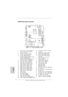 2
2 -
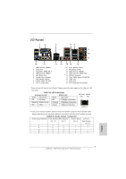 3
3 -
 4
4 -
 5
5 -
 6
6 -
 7
7 -
8
-
9
-
10
-
11
-
12
-
13
-
14
-
15
-
16
-
17
-
18
-
19
-
20
-
21
-
22
-
23
-
24
-
25
-
26
-
27
-
28
-
29
-
30
-
31
-
32
-
33
-
34
-
35
-
36
-
37
-
38
-
39
-
40
-
41
-
42
-
43
-
44
-
45
-
46
-
47
-
48
-
49
-
50
-
51
-
52
-
53
-
54
-
55
-
56
-
57
-
58
-
59
-
60
-
61
-
62
-
63
-
64
-
65
-
66
-
67
-
68
-
69
-
70
-
71
-
72
-
73
-
74
-
75
-
76
-
77
-
78
-
79
-
80
-
81
-
82
-
83
-
84
-
85
-
86
-
87
-
88
-
89
-
90
-
91
-
92
-
93
-
94
-
95
-
96
-
97
-
98
-
99
-
100
-
101
-
102
-
103
-
104
-
105
-
106
-
107
-
108
-
109
-
110
-
111
-
112
-
113
-
114
-
115
-
116
-
117
-
118
-
119
-
120
-
121
-
122
-
123
-
124
-
125
-
126
-
127
-
128
-
129
-
130
-
131
-
132
-
133
-
134
-
135
-
136
-
137
-
138
-
139
-
140
-
141
-
142
-
143
-
144
-
145
-
146
-
147
-
148
-
149
-
150
-
151
-
152
-
153
-
154
-
155
-
156
-
157
-
158
-
159
-
160
-
161
-
162
-
163
-
164
-
165
-
166
-
167
-
168
-
169
-
170
-
171
-
172
-
173
-
174
-
175
-
176
-
177
-
178
-
179
-
180
-
181
-
182
-
183
-
184
-
185
-
186
-
187
-
188
-
189
-
190
-
191
-
192
-
193
-
194
-
195
-
196
-
197
-
198
-
199
-
200
-
201
-
202
-
203
-
204
-
205
-
206
-
207
-
208
-
209
-
210
-
211
-
212
-
213
-
214
-
215
-
216
-
217
-
218
-
219
-
220
-
221
-
222
-
223
-
224
-
225
-
226
-
227
-
228
-
229
-
230
-
231
-
232
-
233
-
234
-
235
-
236
-
237
-
238
-
239
-
240
-
241
-
242
-
243
-
244
-
245
-
246
-
247
-
248
-
249
-
250
-
251
-
252
-
253
-
254
-
255
-
256
-
257
-
258
-
259
-
260
-
261
-
262
-
263
-
264
-
265
-
266
-
267
-
268
-
269
-
270
-
271
-
272
-
273
-
274
-
275
-
276
-
277
-
278
-
279
-
280
-
281
-
282
-
283
-
284
-
285
-
286
-
287
-
288
-
289
-
290
-
291
-
292
-
293
-
294
-
295
-
296
-
297
-
298
-
299
-
300
-
301
-
302
-
303
-
304
-
305
-
306
-
307
-
308
-
309
-
310
-
311
-
312
-
313
-
314
-
315
-
316
-
317
-
318
-
319
-
320
-
321
-
322
 |
 |
1
ASRock
Z68 Extreme4 Gen3
Motherboard
English
Copyright Notice:
No part of this installation guide may be reproduced, transcribed, transmitted, or trans-
lated in any language, in any form or by any means, except duplication of documentation
by the purchaser for backup purpose, without written consent of ASRock Inc.
Products and corporate names appearing in this guide may or may not be registered
trademarks or copyrights of their respective companies, and are used only for identi
fi
ca-
tion or explanation and to the owners’ bene
fi
t, without intent to infringe.
Disclaimer:
Speci
fi
cations and information contained in this guide are furnished for informational use
only and subject to change without notice, and should not be constructed as a commit-
ment by ASRock. ASRock assumes no responsibility for any errors or omissions that may
appear in this guide.
With respect to the contents of this guide, ASRock does not provide warranty of any kind,
either expressed or implied, including but not limited to the implied warranties or condi-
tions of merchantability or
fi
tness for a particular purpose. In no event shall ASRock, its
directors, of
fi
cers, employees, or agents be liable for any indirect, special, incidental, or
consequential damages (including damages for loss of pro
fi
ts, loss of business, loss of
data, interruption of business and the like), even if ASRock has been advised of the pos-
sibility of such damages arising from any defect or error in the guide or product.
This device complies with Part 15 of the FCC Rules. Operation is subject to the following
two conditions:
(1) this device may not cause harmful interference, and
(2) this device must accept any interference received, including interference that
may cause undesired operation.
CALIFORNIA, USA ONLY
The Lithium battery adopted on this motherboard contains Perchlorate, a toxic substance
controlled in Perchlorate Best Management Practices (BMP) regulations passed by the
California Legislature. When you discard the Lithium battery in California, USA, please
follow the related regulations in advance.
“Perchlorate Material-special handling may apply, see
www.dtsc.ca.gov/hazardouswaste/perchlorate”
ASRock Website: http://www.asrock.com
Published June 2011
Copyright
©
2011 ASRock INC. All rights reserved.