ASRock Z68M-ITX/HT User Manual
ASRock Z68M-ITX/HT Manual
 |
View all ASRock Z68M-ITX/HT manuals
Add to My Manuals
Save this manual to your list of manuals |
ASRock Z68M-ITX/HT manual content summary:
- ASRock Z68M-ITX/HT | User Manual - Page 1
Z68M-ITX/HT User Manual Version 1.0 Published July 2011 Copyright©2011 ASRock INC. All rights reserved. 1 - ASRock Z68M-ITX/HT | User Manual - Page 2
purchaser for backup purpose, without written consent of ASRock Inc. Products and corporate names appearing in this manual may or may not be registered trademarks or copyrights , USA ONLY The Lithium battery adopted on this motherboard contains Perchlorate, a toxic substance controlled in Perchlorate - ASRock Z68M-ITX/HT | User Manual - Page 3
installation Precautions 15 2.3 CPU Installation 16 2.4 Installation of Heatsink and CPU fan 18 2.5 Installation of Memory Modules (DIMM 19 2.6 Expansion Slot (PCI Express Slot 20 2.7 Dual Monitor and Surround Display Features 21 2.8 ASRock Smart Remote Installation Guide 24 2.9 Jumpers Setup - ASRock Z68M-ITX/HT | User Manual - Page 4
Screen 37 3.4 Advanced Screen 40 3.4.1 CPU Con guration 41 3.4.2 North Bridge Con guration 43 3.4.3 South Bridge Con guration 45 3.4.4 Storage Con guration 4 Software Support 54 4.1 Install Operating System 54 4.2 Support CD Information 54 4.2.1 Running Support CD 54 4.2.2 Drivers Menu 54 - ASRock Z68M-ITX/HT | User Manual - Page 5
about the model you are using. www.asrock.com/support/index.asp 1.1 Package Contents ASRock Z68M-ITX/HT Motherboard (Mini-ITX Form Factor: 6.7-in x 6.7-in, 17.0 cm x 17.0 cm) ASRock Z68M-ITX/HT Quick Installation Guide ASRock Z68M-ITX/HT Support CD 2 x Serial ATA (SATA) Data Cables (Optional - ASRock Z68M-ITX/HT | User Manual - Page 6
Video HD Technology, Intel® HD Graphics 2000/3000, Intel® Advanced Vector Extensions (AVX) - Pixel Shader 4.1, DirectX 11 with Intel® Ivy Bridge CPU, DirectX 10.1 with Intel® Sandy Bridge CPU - Max. shared memory 1759MB (see CAUTION 4) - Three VGA Output options: D-Sub, DVI-D and HDMI (see CAUTION - ASRock Z68M-ITX/HT | User Manual - Page 7
connectors - 1 x CIR header - 1 x Power LED header - CPU/Chassis FAN connector - 24 pin ATX power connector - 4 pin 12V power connector - Front panel audio connector - 2 x USB 2.0 headers (support 4 USB 2.0 ports) - 64Mb AMI BIOS - AMI UEFI Legal BIOS with GUI support - Supports "Plug and Play" 7 - ASRock Z68M-ITX/HT | User Manual - Page 8
ready power supply is required) (see CAUTION 18) * For detailed product information, please visit our website: http://www.asrock.com WARNING Please realize that there is a certain risk involved with overclocking, including adjusting the setting in the BIOS, applying Untied Overclocking Technology - ASRock Z68M-ITX/HT | User Manual - Page 9
the setting of "Hyper Threading Technology", please check page 41. 2. This motherboard supports Dual Channel Memory Technology. Before you implement Dual Channel Memory Technology, make sure to read the installation guide of memory modules on page 19 for proper installation. 3. Due to the operating - ASRock Z68M-ITX/HT | User Manual - Page 10
embedded in Flash ROM. This convenient BIOS update tool allows you to update system BIOS without entering operating systems rst like MS-DOS or Windows®. With this utility, you can press key during the POST or press key to BIOS setup menu to access ASRock Instant Flash. Just launch this - ASRock Z68M-ITX/HT | User Manual - Page 11
regulated by European Union to de ne the power consumption for the completed system. According to EuP, the total AC power of the completed system shall be under 1.00W in off mode condition. To meet EuP standard, an EuP ready motherboard and an EuP ready power supply are required. According to Intel - ASRock Z68M-ITX/HT | User Manual - Page 12
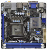
CPU Socket 4 SATA2 Connector (SATA_2 (PORT 4), Blue) 14 PCI Express 2.0 x16 Slot (PCIE1, Blue) 5 SATA2 Connector (SATA_3 (PORT 3), Blue) 15 Front Panel Audio Header 6 Clear CMOS Jumper (CLRCMOS1) (HD_AUDIO1, White) 7 Intel Z68 Chipset 16 ATX 12V Power Connector (ATX12V1) 8 ATX Power Connector - ASRock Z68M-ITX/HT | User Manual - Page 13
1.4 I/O Panel 1 2 34 58 69 7 10 15 14 1 USB 2.0 Ports (USB01) 2 D-Sub Port 3 USB 2.0 Ports (USB23) * 4 LAN RJ-45 Port 5 Central / Bass (Orange) 6 Rear Speaker (Black) 7 Optical SPDIF Out Port 8 Line In (Light Blue) 13 12 11 ** 9 Front Speaker (Lime) 10 Microphone (Pink) 11 USB 3.0 Ports ( - ASRock Z68M-ITX/HT | User Manual - Page 14
down and front), which is compatible with most of the chassis on the market. For the installation guide, please refe to page 24 for details. * OS support: Windows® VistaTM / 7 (above Home Premium) CIR Remote Receiver Remote Controller Introduction NAVIGATION BUTTONS CIR Remote Controller PLAYBACK - ASRock Z68M-ITX/HT | User Manual - Page 15
Precautions Take note of the following precautions before you install motherboard components or change any motherboard settings. 1. Unplug the power cord from the wall socket before touching any component. 2. To avoid damaging the motherboard components due to static electricity, NEVER place your - ASRock Z68M-ITX/HT | User Manual - Page 16
Socket Body 1155-Pin Socket Overview Before you insert the 1155-Pin CPU into the socket, please check if the CPU surface is unclean or if there is any bent pin on the socket. Do not force to insert the CPU into the socket 2. This cap must be placed if returning the motherboard for after service. 16 - ASRock Z68M-ITX/HT | User Manual - Page 17
key Pin1 Pin1 orientation key notch 1155-Pin CPU alignment key 1155-Pin Socket For proper inserting, please ensure to match the two orientation key notches of the CPU with the two alignment keys of the socket. Step 3-3. Carefully place the CPU into the socket by using a purely vertical motion - ASRock Z68M-ITX/HT | User Manual - Page 18
installation, please kindly refer to the instruction manuals of your CPU fan and heatsink. Below is an example to illustrate the installation of the heatsink for 1155-Pin CPU. Step 1. Apply thermal interface material onto center of IHS on the socket surface. Apply Thermal Interface Material Step - ASRock Z68M-ITX/HT | User Manual - Page 19
is unable to activate the Dual Channel Memory Technology. 3. Some DDR3 1GB double-sided DIMMs with 16 chips may not work on this motherboard. It is not recommended to install them on this motherboard. Installing a DIMM Please make sure to disconnect power supply before adding or removing DIMMs or - ASRock Z68M-ITX/HT | User Manual - Page 20
supply is switched off or the power cord is unplugged. Please read the documentation of the expansion card and make necessary hardware settings for the card before you start the installation. Remove the system unit cover (if your motherboard is already installed in a chassis). Remove the bracket - ASRock Z68M-ITX/HT | User Manual - Page 21
VGA card to this motherboard. This motherboard also provides independent display controllers for DVI-D, D-Sub and HDMI to support dual VGA output so port DVI-D port HDMI port 2. If you have installed onboard VGA driver from our support CD to your system already, you can freely enjoy the bene ts - ASRock Z68M-ITX/HT | User Manual - Page 22
Enter "Share Memory" option to adjust the memory capability to [ motherboard. 4. Install the onboard VGA driver and the add-on PCI Express VGA card driver to your system. If you have installed the drivers already, there is no need to install them again. 5. Set up a multi-monitor display. For Windows - ASRock Z68M-ITX/HT | User Manual - Page 23
For Windows® 7 / 7 64-bit supported on this motherboard. To use HDCP function with this motherboard, you need to adopt the monitor that supports HDCP function as well. Therefore, you can enjoy the superior display quality with high-de nition HDCP encryption contents. Please refer to below instruction - ASRock Z68M-ITX/HT | User Manual - Page 24
chassis on the market. 3. The Multi-Angle CIR Receiver does not support Hot-Plug function. Please install it before you boot the system. * ASRock Smart Remote is only supported by some of ASRock motherboards. Please refer to ASRock website for the motherboard support list: http://www.asrock.com 24 - ASRock Z68M-ITX/HT | User Manual - Page 25
power cord from the power supply. After waiting for 15 seconds, use a jumper cap to short pin2 and pin3 on CLRCMOS1 for 5 seconds. However, please do not clear the CMOS right after you update the BIOS damage of the motherboard! Serial ATAII ATAII (SATAII) connectors support SATA data cables for - ASRock Z68M-ITX/HT | User Manual - Page 26
) 1 GND IRTX IRRX ATX+5VSB Besides four default USB 2.0 ports on the I/O panel, there are two USB 2.0 headers on this motherboard. Each USB 2.0 header can support two USB 2.0 ports. This header can be used to connect the remote controller receiver. Front Panel Audio Header (9-pin HD_AUDIO1) (see - ASRock Z68M-ITX/HT | User Manual - Page 27
Jack Sensing, but the panel wire on the chassis must support HDA to function correctly. Please follow the instruction in our manual and chassis manual to install your system. 2. If you use AC'97 audio panel, please install it to the front panel audio header as below: A. Connect Mic_IN (MIC) - ASRock Z68M-ITX/HT | User Manual - Page 28
even without the fan speed control function. If you plan to connect the 3-Pin CPU fan to the CPU fan connector on this motherboard, please connect it to Pin 1-3. Pin 1-3 Connected 3-Pin Fan Installation ATX Power Connector 24 (24-pin ATXPWR1) (see p.12 No. 8) 12 13 Please connect an ATX - ASRock Z68M-ITX/HT | User Manual - Page 29
adopts Intel® Z68 chipset that supports Serial ATA3 (SATA3) hard disks and RAID (RAID 0, RAID 1, RAID 10, RAID 5, Intel Rapid Storage and Intel Smart Response Technology) functions. You may install SATA3 hard disks on this motherboard for internal storage devices. This section will guide you to - ASRock Z68M-ITX/HT | User Manual - Page 30
HDDs while the system is still power-on and in working condition. 2.14 Hot Plug and Hot Swap Functions for SATA3 HDDs This motherboard supports Hot Plug and Hot Swap functions for SATA3 in RAID / AHCI mode. Intel® Z68 chipset provide hardware support for Advanced Host controller Interface (AHCI - ASRock Z68M-ITX/HT | User Manual - Page 31
installed into system properly. The latest SATA / SATAII / SATA3 driver is available on our support website: www.asrock.com 4. Make sure to use the SATA power cable & data cable, which are from our motherboard package. 5. Please follow below instructions step by step to reduce the risk of HDD crash - ASRock Z68M-ITX/HT | User Manual - Page 32
do follow below instruction sequence to process the Hot Plug, improper procedure will cause the SATA / SATAII / SATA3 HDD damage and data loss. Step 1 Please connect SATA power cable 1x4-pin end Step 2 Connect SATA data cable to (White) to the power supply 1x4-pin cable. the motherboard's SATAII - ASRock Z68M-ITX/HT | User Manual - Page 33
and the document in the support CD, "Guide to Intel Rapid Storage", which is located in the folder at the following path: .. \ Intel Rapid Storage Information If you want to use "Intel Rapid Storage" in Windows® environment, install "SATAII driver" from the Support CD again so that "Intel Rapid - ASRock Z68M-ITX/HT | User Manual - Page 34
® XP / XP 64-bit OS on your SATA / SATAII / SATA3 HDDs without RAID functions, please follow below steps. AHCI mode is not supported under Windows® XP / XP 64-bit OS. Using SATA / SATAII / SATA3 HDDs without NCQ function STEP 1: Set up UEFI. A. Enter UEFI SETUP UTILITY Advanced screen SATA Con - ASRock Z68M-ITX/HT | User Manual - Page 35
system. The UEFI chip on the motherboard stores the UEFI SETUP UTILITY. You Power-On-Self-Test (POST) to enter the UEFI SETUP UTILITY, otherwise, POST will continue with its test software is constantly being updated, the following UEFI setup Tweaker To set up overclocking features Advanced To set up - ASRock Z68M-ITX/HT | User Manual - Page 36
3.1.2 Navigation Keys Please check the following table for the function description of each navigation key. Navigation Key(s) Function Description / / + / Moves cursor left or right to select Screens Moves cursor up or down to select items To change option for the - ASRock Z68M-ITX/HT | User Manual - Page 37
3.3 OC Tweaker Screen In the OC Tweaker screen, you can set up overclocking features. CPU Control CPU Ratio Setting Use this item to change the ratio value of this motherboard. GT Over Clock Use this to enable or disable GT Over Clock by Internal Graphics Device. The default value is [Disabled]. - ASRock Z68M-ITX/HT | User Manual - Page 38
this item to add voltage when CPU is in Turbo mode. DRAM Timing Control Load XMP Setting Use this to load XMP setting. Con guration options: [Auto], [Pro le 1] and [Pro le 2]. The default value is [Auto]. CAS# Latency (tCL) Use this item to change CAS# Latency (tCL) Auto/Manual setting. The default - ASRock Z68M-ITX/HT | User Manual - Page 39
Voltage Control DRAM Voltage Use this to select DRAM Voltage. The default value is [Auto]. User Default In this option, you are allowed to load and save three user defaults according to your own requirements. 39 - ASRock Z68M-ITX/HT | User Manual - Page 40
the con gurations for the following items: CPU Con guration, North Bridge Con guration, South Bridge Con guration, Storage Con guration, Super IO ROM. This convenient UEFI update tool allows you to update system UEFI without entering operating systems rst like MS-DOS or Windows®. Just launch this - ASRock Z68M-ITX/HT | User Manual - Page 41
of adjacent cache lines. Enhance Halt State (C1E) All processors support the Halt State (C1). The C1 state is supported through the native processor instructions HLT and MWAIT and requires no hardware support from the chipset. In the C1 power state, the processor maintains the context of the system - ASRock Z68M-ITX/HT | User Manual - Page 42
CPU Thermal Throttling You may select [Enabled] to enable CPU internal thermal control mechanism to keep the CPU from overheated. Intel to execute code. This option will be hidden if the current CPU does not support No-Excute Memory Protection. Local x2APIC Use this to enable or disable Local x2APIC - ASRock Z68M-ITX/HT | User Manual - Page 43
Bridge Configuration Low MMIO Align Low MMIO resources align at 64MB/1024MB. The default value is [64MB]. VT-d Use this to enable or disable Intel® VT VGA Share Memory This allows you to set onboard VGA share memory feature. The . The default value is [Disabled]. For Windows® XP / XP 64-bit / VistaTM - ASRock Z68M-ITX/HT | User Manual - Page 44
the motherboard through ef cient memory utilization. In DVMT mode, the graphics driver allocates memory as needed for running graphics applications and is cooperatively using this memory with other system components. This item will not be used under Windows® VistaTM / 7 OS because the driver will - ASRock Z68M-ITX/HT | User Manual - Page 45
allows you to set the power state after an unexpected AC/power loss. If [Power Off] is selected, the AC/power remains off when the power recovers. If [Power On] is selected, the AC/power resumes and the system starts to boot up when the power recovers. Deep Sx Mobile platforms support Deep S4/S5 in - ASRock Z68M-ITX/HT | User Manual - Page 46
value is [AHCI Mode]. AHCI (Advanced Host Controller Interface) supports NCQ and other new features that will improve SATA disk performance legacy OS. If native OS (Windows® XP / VistaTM / 7) is installed, please select [Enhanced]. SATA Aggressive Link Power Management This item appears only when - ASRock Z68M-ITX/HT | User Manual - Page 47
Hard Disk S.M.A.R.T. Use this item to enable or disable the S.M.A.R.T. (Self-Monitoring, Analysis, and Reporting Technology) feature. Con guration options: [Disabled] and [Enabled]. 3.4.5 Super IO Configuration CIR Controller Use this item to enable or disable CIR controller. 47 - ASRock Z68M-ITX/HT | User Manual - Page 48
-detect or disable the Suspend-toRAM feature. Select [Auto] will enable this feature if the OS supports it. Check Ready Bit Use this item to enable or disable the feature Check Ready Bit. PS/2 Keyboard Power On Use this item to enable or disable PS/2 keyboard to turn on the system from - ASRock Z68M-ITX/HT | User Manual - Page 49
to use only under UEFI setup and Windows / Linux OS. Legacy USB 3.0 Support Use this option to enable or disable legacy support for USB 3.0 devices. The default value is [Disabled]. To use Instant Flash, USB Keyboard/Remote Power On and USB Mouse Power On functions on USB 3.0 devices, please enable - ASRock Z68M-ITX/HT | User Manual - Page 50
the status of the hardware on your system, including the parameters of the CPU temperature, motherboard temperature, CPU fan speed, chassis fan speed, and the critical voltage. CPU Fan Setting This allows you to set the CPU fan speed. Con guration options: [Full On] and [Automatic Mode]. The default - ASRock Z68M-ITX/HT | User Manual - Page 51
3.6 Boot Screen In this section, it will display the available devices on your system for you to con gure the boot settings and the boot priority. Setup Prompt Timeout This shows the number of seconds to wait for setup activation key. 65535(0XFFFF) means inde nite waiting. Bootup Num-Lock If this - ASRock Z68M-ITX/HT | User Manual - Page 52
3.7 Security Screen In this section, you may set or change the supervisor/user password for the system. For the user password, you may also clear it. 52 - ASRock Z68M-ITX/HT | User Manual - Page 53
3.8 Exit Screen Save Changes and Exit When you select this option, it will pop-out the following message, "Save con guration changes and exit setup?" Select [OK] to save the changes and exit the UEFI SETUP UTILITY. Discard Changes and Exit When you select this option, it will pop-out the following - ASRock Z68M-ITX/HT | User Manual - Page 54
install the necessary drivers to activate the devices. 4.2.3 Utilities Menu The Utilities Menu shows the applications software that the motherboard supports. Click on a speci c item then follow the installation wizard to install it. 4.2.4 Contact Information If you need to contact ASRock or want to - ASRock Z68M-ITX/HT | User Manual - Page 55
HDD Larger Than 2TB This motherboard is adopting UEFI BIOS that allows Windows® OS to be installed on a large size HDD (>2TB). Please follow below procedure to install the operating system. 1. Please make sure to use Windows® VistaTM 64-bit (with SP1 or above) or Windows® 7 64-bit. 2. Press or
-
 1
1 -
 2
2 -
 3
3 -
 4
4 -
 5
5 -
 6
6 -
 7
7 -
8
-
9
-
10
-
11
-
12
-
13
-
14
-
15
-
16
-
17
-
18
-
19
-
20
-
21
-
22
-
23
-
24
-
25
-
26
-
27
-
28
-
29
-
30
-
31
-
32
-
33
-
34
-
35
-
36
-
37
-
38
-
39
-
40
-
41
-
42
-
43
-
44
-
45
-
46
-
47
-
48
-
49
-
50
-
51
-
52
-
53
-
54
-
55
 |
 |
1
Z68M-ITX/HT
User Manual
Version 1.0
Published July 2011
Copyright©2011 ASRock INC. All rights reserved.