ASRock Z77 Extreme4 User Manual - Page 19
Installation of CPU Fan and Heatsink - lga 1155
 |
View all ASRock Z77 Extreme4 manuals
Add to My Manuals
Save this manual to your list of manuals |
Page 19 highlights
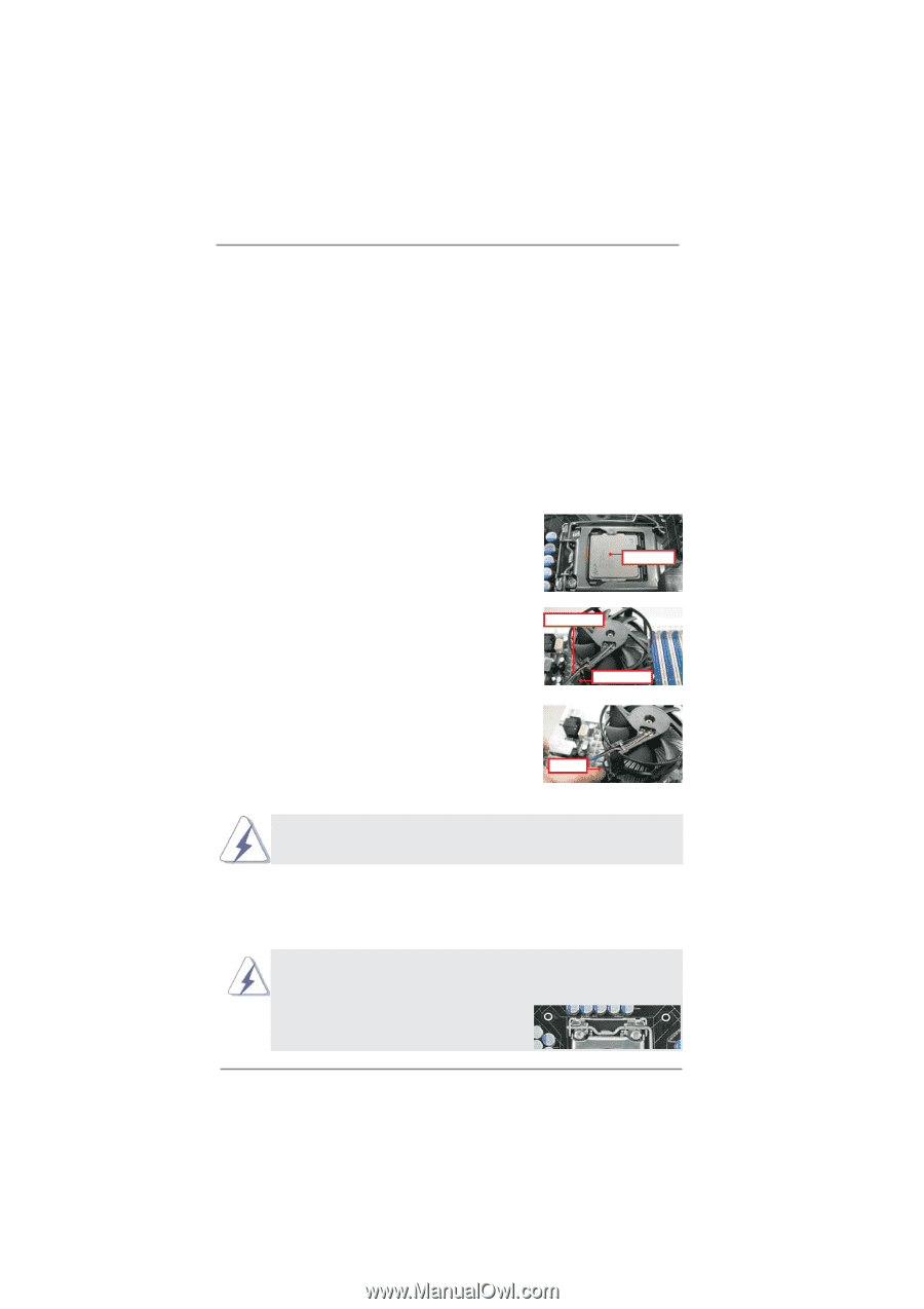
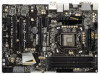
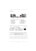
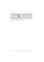
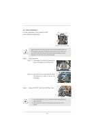
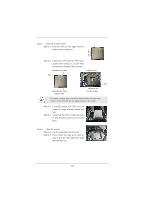
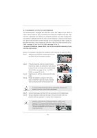
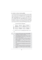
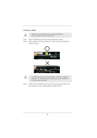
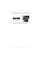
2.4 Installation of CPU Fan and Heatsink This motherboard is equipped with 1155-Pin socket that supports Intel 1155-Pin CPUs. Please adopt the type of heatsink and cooling fan compliant with Intel 1155Pin CPU to dissipate heat. Before you install the heatsink, you need to spray thermal interface material between the CPU and the heatsink to improve heat dissipation. Ensure that the CPU and the heatsink are securely fastened and in good contact with each other. Then connect the CPU fan to the CPU_FAN connector (CPU_ FAN1, see page 13, No. 3 or CPU_FAN2, see page 13. No. 5). For proper installation, please kindly refer to the instruction manuals of your CPU fan and heatsink. Below is an example to illustrate the installation of the heatsink for 1155-Pin CPUs. Step 1. Apply thermal interface material onto the cen- ter of the IHS on the socket's surface. Apply Thermal Interface Material Step 2. Step 3. Step 4. Place the heatsink onto the socket. Ensure that the fan cables are oriented on side closest to the CPU fan connector on the motherboard (CPU_FAN1, see page 13, No. 3 or CPU_ FAN2, see page 13. No. 5). Align fasteners with the motherboard throughholes. Rotate the fastener clockwise, then press down on fastener caps with thumb to install and lock. Repeat with remaining fasteners. Fan cables on side closest to MB header Fastener slots pointing straight out Press Down (4 Places) If you press down the fasteners without rotating them clockwise, the heatsink cannot be secured on the motherboard. Step 5. Connect fan header with the CPU fan connector on the motherboard. Step 6. Secure redundant cable with tie-wrap to ensure the cable does not interfere with fan operation or contact other components. Please be noticed that this motherboard supports Combo Cooler Option (C.C.O.), which provides flexible options to adopt three different CPU cooler types, Socket LGA 775, LGA 1155 and LGA 1156. The white throughholes are for Socket LGA 1155/1156 CPU fan. 19
-
 1
1 -
2
-
3
-
4
-
5
-
6
-
7
-
8
-
9
-
10
-
11
-
12
-
13
-
 14
14 -
 15
15 -
 16
16 -
 17
17 -
 18
18 -
 19
19 -
 20
20 -
 21
21 -
 22
22 -
 23
23 -
 24
24 -
25
-
26
-
27
-
28
-
29
-
30
-
31
-
32
-
33
-
34
-
35
-
36
-
37
-
38
-
39
-
40
-
41
-
42
-
43
-
44
-
45
-
46
-
47
-
48
-
49
-
50
-
51
-
52
-
53
-
54
-
55
-
56
-
57
-
58
-
59
-
60
-
61
-
62
-
63
-
64
-
65
-
66
-
67
-
68
-
69
-
70
-
71
-
72
-
73
-
74
-
75
-
76
-
77
-
78
-
79
 |
 |