ASRock Z77 Extreme4 User Manual - Page 37
Consumer Infrared Module Header - audio
 |
View all ASRock Z77 Extreme4 manuals
Add to My Manuals
Save this manual to your list of manuals |
Page 37 highlights
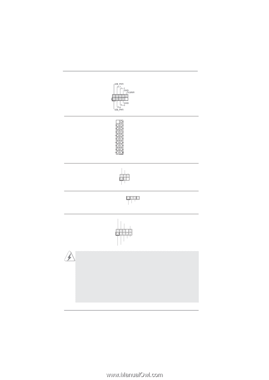
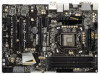
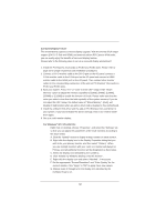
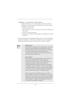
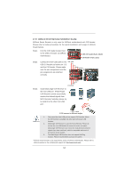
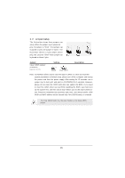
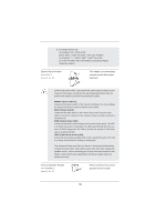
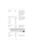
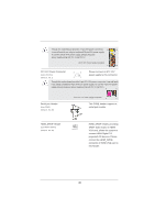
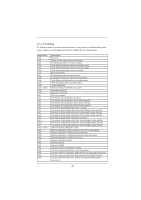
(9-pin USB6_7) (see p.13, No. 24) USB 3.0 Header (19-pin USB3_4_5) (see p.13, No. 9) Vbus IntA_P4_SSRXIntA_P4_SSRX+ GND IntA_P4_SSTXIntA_P4_SSTX+ GND IntA_P4_DIntA_P4_D+ Vbus IntA_P5_SSRXIntA_P5_SSRX+ GND IntA_P5_SSTXIntA_P5_SSTX+ GND IntA_P5_DIntA_P5_D+ DUMMY Besides four default USB 3.0 ports on the I/O panel, there is one USB 3.0 header on this motherboard. This USB 3.0 header can support two USB 3.0 ports. Infrared Module Header (5-pin IR1) (see p.13, No. 30) IRTX +5VSB DUMMY 1 GND IRRX This header supports an optional wireless transmitting and receiving infrared module. Consumer Infrared Module Header (4-pin CIR1) (see p.13 No. 27) 1 GND IRTX IRRX ATX+5VSB This header can be used to connect the remote controller receiver. Front Panel Audio Header (9-pin HD_AUDIO1) (see p.13, No. 31) GND PRESENCE# MIC_RET OUT_RET 1 OUT2_L J_SENSE OUT2_R MIC2_R MIC2_L This is an interface for front panel audio cable that allows convenient connection and control of audio devices. 1. High Definition Audio supports Jack Sensing, but the panel wire on the chassis must support HDA to function correctly. Please follow the instruction in our manual and chassis manual to install your system. 2. If you use AC'97 audio panel, please install it to the front panel audio header as below: A. Connect Mic_IN (MIC) to MIC2_L. B. Connect Audio_R (RIN) to OUT2_R and Audio_L (LIN) to OUT2_L. C. Connect Ground (GND) to Ground (GND). D. MIC_RET and OUT_RET are for HD audio panel only. You don't need to connect them for AC'97 audio panel. 37
-
 1
1 -
2
-
3
-
4
-
5
-
6
-
7
-
8
-
9
-
10
-
11
-
12
-
13
-
14
-
15
-
16
-
17
-
18
-
19
-
20
-
21
-
22
-
23
-
24
-
25
-
26
-
27
-
28
-
29
-
30
-
31
-
 32
32 -
 33
33 -
 34
34 -
 35
35 -
 36
36 -
 37
37 -
 38
38 -
 39
39 -
 40
40 -
 41
41 -
 42
42 -
43
-
44
-
45
-
46
-
47
-
48
-
49
-
50
-
51
-
52
-
53
-
54
-
55
-
56
-
57
-
58
-
59
-
60
-
61
-
62
-
63
-
64
-
65
-
66
-
67
-
68
-
69
-
70
-
71
-
72
-
73
-
74
-
75
-
76
-
77
-
78
-
79
 |
 |