ASRock Z77 WS User Manual
ASRock Z77 WS Manual
 |
View all ASRock Z77 WS manuals
Add to My Manuals
Save this manual to your list of manuals |
ASRock Z77 WS manual content summary:
- ASRock Z77 WS | User Manual - Page 1
Z77 WS User Manual Version 1.0 Published August 2012 Copyright©2012 ASRock INC. All rights reserved. 1 - ASRock Z77 WS | User Manual - Page 2
any form or by any means, except duplication of documentation by the purchaser for backup purpose, without written consent of ASRock Inc. Products and corporate names appearing in this manual may or may not be registered trademarks or copyrights of their respective companies, and are used only for - ASRock Z77 WS | User Manual - Page 3
HDDs ..... 55 2.19 SATA / SATA2 / SATA3 HDD Hot Plug Feature and Operation Guide 56 2.20 Driver Installation Guide 58 2.21 Installing Windows® 7 / 7 64-bit / VistaTM / VistaTM 64-bit With RAID Functions 58 2.22 Installing Windows® 7 / 7 64-bit / VistaTM / VistaTM 64-bit / XP / XP 64-bit Without - ASRock Z77 WS | User Manual - Page 4
Windows® 7 / 7 64-bit / VistaTM / VistaTM 64-bit Without RAID Functions 59 2.23 Teaming Function Operation Guide 3.4.5 Intel(R) Rapid Start Technology 78 3.4.6 Intel(R) Smart Support 88 4.1 Install Operating System 88 4.2 Support CD Information 88 4.2.1 Running Support CD 88 4.2.2 Drivers - ASRock Z77 WS | User Manual - Page 5
guide to BIOS setup and information of the Support CD. Because the motherboard specifications and the BIOS software might be updated, the content of this manual will be subject to change without notice. In case any modifications of this manual occur, the updated version will be available on ASRock - ASRock Z77 WS | User Manual - Page 6
ATX Form Factor: 12.0-in x 9.6-in, 30.5 cm x 24.4 cm - Premium Gold Capacitor design (100% Japan-made high-quality Conductive Polymer Capacitors) - Supports 3rd and 2nd Generation Intel - Supports Intel® Turbo Boost 2.0 Technology - Supports Intel® K-Series unlocked CPU - Intel® Z77 - Supports Intel® - ASRock Z77 WS | User Manual - Page 7
and "Hot Plug" functions (SATA3_A4 connector is shared with eSATA3 port) - 4 x SATA2 3.0 Gb/s connectors by Intel® Z77, support RAID (RAID 0, RAID 1, RAID 5, RAID 10, Intel Rapid Storage and Intel Smart Response Technology), NCQ, AHCI and Hot Plug functions I/O Panel - 1 x PS/2 Keyboard/Mouse Port - ASRock Z77 WS | User Manual - Page 8
BIOS with GUI support - Supports "Plug and Play" - ACPI 1.1 Compliance Wake Up Events - Supports jumperfree - SMBIOS 2.3.1 Support - CPU Core, IGPU, DRAM, 1.8V PLL, VTT, VCCSA Voltage Multi-adjustment - Drivers, Utilities, AntiVirus Software (Trial Version), CyberLink MediaEspresso 6.5 Trial, ASRock - ASRock Z77 WS | User Manual - Page 9
Color are only supported under Windows® 7 64-bit / 7. Deep Color mode will be enabled only if the display supports 12bpc in EDID. HBR is supported under Windows® 7 64-bit / 7 / VistaTM 64-bit / VistaTM. 3. ASRock XFast RAM is not supported by Microsoft® Windows® XP / XP 64-bit. Intel® Smart Connect - ASRock Z77 WS | User Manual - Page 10
for you to adjust. In Overclocking, you are allowed to overclock CPU frequency for optimal system performance Windows® desktop in a few seconds. ASRock Instant Flash ASRock Instant Flash is a BIOS flash utility embedded in Flash ROM. This convenient BIOS update tool allows you to update system BIOS - ASRock Z77 WS | User Manual - Page 11
driver, it makes your iPhone charge much quickly from your computer and up to 40% faster than before. ASRock APP Charger allows you to quickly charge many Apple devices simultaneously and even supports in Game: After setting online game's priority higher, it can lower the latency in games. Traffic - ASRock Z77 WS | User Manual - Page 12
during the BIOS update process, ASRock Crashless BIOS will automatically finish the BIOS update procedure after regaining power. Please note that BIOS files need to be placed in the root directory of your USB disk. Only USB2.0 ports support this feature. ASRock Interactive UEFI ASRock Interactive - ASRock Z77 WS | User Manual - Page 13
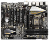
RAM PCIE3 2 oz Copper PCB PCIE4 Z77 WS PCIE5 AUDIO CODEC PCIE6 RoHS CMOS Battery USB3_11_12 USB3_9_10 Intel Z77 RSTBTN PWRBTN Dr. Debug CLRCMOS1 PLED1 64Mb 1 BIOS 1 SPEAKER1 27 26 25 24 23 22 21 1 ATX 12V Power Connector (ATX12V1) 24 Dr. Debug 2 1155-Pin CPU Socket 25 USB 2.0 Header - ASRock Z77 WS | User Manual - Page 14
1.5 I/O Panel 1 23 45 69 7 10 8 11 18 17 16 15 14 13 12 1 PS/2 Keyboard/Mouse Port (Purple/Green) ** 10 Front Speaker (Lime) 2 USB 3.0 Ports (USB3_34) 11 Microphone (Pink) * 3 LAN RJ-45 Port 12 USB 3.0 Ports (USB3_78) 4 USB 2.0 Ports (USB01) 13 IEEE 1394 Port * 5 LAN RJ-45 Port *** - ASRock Z77 WS | User Manual - Page 15
connect a front panel audio cable to the front panel audio header. After restarting your computer, you will find "Mixer" tool on your system. Please select "Mixer ToolBox" , click "Enable playback multi 2nd output" to use front panel audio. *** eSATA3 connector supports SATA Gen3 in cable 1M. 15 - ASRock Z77 WS | User Manual - Page 16
Chapter 2: Installation This is an ATX form factor (12.0" x 9.6", 30.5 x 24.4 cm) motherboard. Before you install the motherboard, study the configuration of your chassis to ensure that the motherboard fits into - ASRock Z77 WS | User Manual - Page 17
In order to provide the LGA 1155 CPU sockets more protection and make the installation process easier, ASRock has added a new protection cover on top of the load plate to replace the former PnP caps that were under the load plate. For the installation of Intel® 1155-Pin CPUs with the new - ASRock Z77 WS | User Manual - Page 18
Pin1 alignment key orientation key notch 1155-Pin CPU alignment key 1155-Pin Socket Pin1 For proper installation, and secure it with the load plate tab under the retention tab. The protection cover will automatically come off by itself. Please save and replace the cover if the processor is - ASRock Z77 WS | User Manual - Page 19
with 1155-Pin socket that supports Intel 1155-Pin CPUs. Please adopt the type of heatsink and cooling fan compliant with Intel 1155Pin kindly refer to the instruction manuals of your CPU fan and heatsink. Below is an example to illustrate the installation of the heatsink for 1155-Pin CPUs. Step 1. - ASRock Z77 WS | User Manual - Page 20
four 240-pin DDR3 (Double Data Rate 3) DIMM slots, and supports Dual Channel Memory Technology. For dual channel configuration, you always need them on this motherboard. 6. For optimal compatibility and stability while overclocking memory frequency, it is recommended to install one memory module on - ASRock Z77 WS | User Manual - Page 21
on the slot such that the notch on the DIMM matches the break on the slot. The DIMM only fits in one correct orientation. It will cause permanent damage to the motherboard and the DIMM if you force the DIMM into the slot at incorrect orientation. Step 3. Firmly insert the DIMM - ASRock Z77 WS | User Manual - Page 22
x16 lane width graphics cards, or to install PCI Express graphics cards to support CrossFireXTM or SLITM function. PCIE3 / PCIE7 (PCIE 3.0 x16 slot) is 2.0 x16 slot) is used for PCI Express x4 lane width graphics cards or ASRock Game Blaster. PCIE6 (PCIE 2.0 x1 slot) is used for a PCI Express x1 - ASRock Z77 WS | User Manual - Page 23
x16 graphics card in the PCIE2 slot. 2. PCIE1, PCIE3, PCIE5 and PCIE7 slots will be disabled if PCIE2 slot is occupied. 3. In CrossFireXTM mode or SLITM mode, environment. 7. Only PCIE1, PCIE2, PCIE3, PCIE5, PCIE6 and PCIE7 slots support Gen 3 speed. To run the PCI Express in Gen 3 speed, please - ASRock Z77 WS | User Manual - Page 24
and Quad SLITM Operation Guide This motherboard supports NVIDIA® SLITM, 3-Way SLITM, 4-Way SLITM and Quad SLITM (Scalable Link Interface) technology that allows you to install up to four identical PCI Express x16 graphics cards. Currently, NVIDIA® SLITM technology supports Windows® XP / XP 64-bit - ASRock Z77 WS | User Manual - Page 25
the ASRock SLI_Bridge_3S Card to the goldfingers on each graphics card. Make sure the ASRock SLI_Bridge_3S Card is firmly in place. ASRock SLI_Bridge_3S cards that are NVIDIA® certified because different types of graphics cards will not work together properly. (Even the GPU chips version shall - ASRock Z77 WS | User Manual - Page 26
connected. Repeat this step on the three graphics cards. Step3. Align and insert the ASRock 3-Way SLI Bridge Card to the goldfingers on each graphics card. Make sure the ASRock 3-Way SLI Bridge Card is firmly in place. ASRock 3-Way SLI Bridge Card Step4. Connect a VGA cable or a DVI cable to the - ASRock Z77 WS | User Manual - Page 27
cards that are NVIDIA® certified because different types of graphics cards will not work together properly. (Even the GPU chips version shall be the same.) Each graphics card should have two goldfingers for the ASRock SLI Bridge Card connectors. Insert one graphics card into the PCIE1 slot, - ASRock Z77 WS | User Manual - Page 28
Installation and Setup Install the graphics card drivers to your system. After that, you can enable the MultiGraphics Processing Unit (GPU) feature in the NVIDIA® nView system tray utility. Please follow the below procedures to enable the multi-GPU feature. For Windows® XP / XP 64-bit OS: (For SLITM - ASRock Z77 WS | User Manual - Page 29
® VistaTM / VistaTM 64-bit / 7 / 7 64-bit OS: (For SLITM and Quad SLITM mode) A. Click the Start icon on your Windows taskbar. B. From the pop-up menu, select All Programs, and then click NVIDIA Corporation. C. Select NVIDIA Control Panel tab. D. Select Control Panel tab. E. From the - ASRock Z77 WS | User Manual - Page 30
For Windows® VistaTM / VistaTM 64-bit / 7 / 7 64-bit OS: (For 3-Way SLITM or 4-Way SLITM mode) A. Follow step A to D on page 29. B. From the pop-up menu, - ASRock Z77 WS | User Manual - Page 31
supported with Windows® VistaTM / 7 OS only. Please check AMD's website for CrossFireXTM driver updates. 1. If a customer incorrectly configures their system they will has released or will release in the future, please refer to AMD graphics card manuals for detailed installation guide. Step 1. - ASRock Z77 WS | User Manual - Page 32
Step 2. Connect two Radeon graphics cards by installing a CrossFire Bridge on the CrossFire Bridge Interconnects on the top of the Radeon graphics cards. (The CrossFire Bridge is provided with the graphics card you purchase, not bundled with this motherboard. Please refer to your graphics card - ASRock Z77 WS | User Manual - Page 33
CrossFireXTM-Ready Graphics Cards Step 1. Install identical 3-Way CrossFireXTM-ready graphics cards that are AMD® certified because different types of graphics cards will not work together properly. (Even the GPU chips version shall be the same.) Insert one graphics card into PCIE1 slot, another - ASRock Z77 WS | User Manual - Page 34
CrossFireXTM-Ready Graphics Cards Step 1. Install identical 4-Way CrossFireXTM-ready graphics cards that are AMD® certified because different types of graphics cards will not work together properly. (Even the GPU chips version shall be the same.) Insert one graphics card into PCIE1 slot, another - ASRock Z77 WS | User Manual - Page 35
. Please check AMD website for ATITM driver updates. Step 3. Step 4. Step 5. Install the required drivers to your system. For Windows® XP OS: A. AMD recommends Windows® XP Service Pack 2 or higher to be installed (If you have Windows® XP Service Pack 2 or higher installed in your - ASRock Z77 WS | User Manual - Page 36
"Enable CrossFireTM", the CrossFireXTM function may not work actually. Your computer will automatically reboot. After restarting your computer, please confirm whether the option "Enable further information of AMD CrossFireXTM technology, please check AMD website for updates and details. 36 - ASRock Z77 WS | User Manual - Page 37
is inserted to this motherboard. 4. Install the onboard VGA driver and the add-on PCI Express VGA card driver to your system. If you have installed the drivers already, there is no need to install them again. 5. Set up a multi-monitor display. For Windows® XP / XP 64-bit OS: Right click on desktop - ASRock Z77 WS | User Manual - Page 38
Click "Apply" or "OK" to apply these new values. G. Repeat steps C through E for the display icon identified by the numbers three to thirteen. For Windows® 7 / 7 64-bit / VistaTM / VistaTM 64-bit OS: Right click the desktop, choose "Personalize", and select the "Display Settings" tab so that you can - ASRock Z77 WS | User Manual - Page 39
HDCP function with this motherboard, you need to adopt a monitor that supports HDCP function as well. Therefore, you can enjoy the superior display quality with high-definition HDCP encryption contents. Please refer to the instructions below for more details about HDCP function. What is HDCP? HDCP - ASRock Z77 WS | User Manual - Page 40
45 GND IRTX IRRX ATX+5VSB Step3. Install Multi-Angle CIR Receiver or to enter BIOS Setup Utility. Make sure the option shut down your system and install Multi-Angle CIR Receiver to the other front USB port then try again. Step5. Enter Windows. Execute ASRock support CD and install CIR Driver - ASRock Z77 WS | User Manual - Page 41
chassis on the market. 3. The Multi-Angle CIR Receiver does not support Hot-Plug function. Please install it before you boot the system. * ASRock Smart Remote is only supported by some of ASRock motherboards. Please refer to ASRock website for the motherboard support list: http://www.asrock.com 41 - ASRock Z77 WS | User Manual - Page 42
to clear the CMOS when you just finish updating the BIOS, you must boot up the system first, and then shut it down before you do the clear-CMOS action. Please be noted that the password, date, time, user default profile, 1394 GUID and MAC address will be cleared only if the CMOS battery is - ASRock Z77 WS | User Manual - Page 43
: see p.13, No. 14) These six Serial ATA3 (SATA3) connectors support SATA data cables for internal storage devices. The current SATA3 interface allows up to on the rear I/O has been connected, the internal SATA3_A4 will not function. SATA3_0 SATA3_A3 SATA3_A1 SATA3_1 SATA3_A4 SATA3_A2 Serial ATA - ASRock Z77 WS | User Manual - Page 44
DUMMY 1 GND P+2 P-2 USB_PWR Besides two default USB 2.0 ports on the I/O panel, there are three USB 2.0 headers on this motherboard. Each USB 2.0 header can support two USB 2.0 ports. (9-pin USB6_7) (see p.13, No. 27) USB 3.0 Header (19-pin USB3_9_10) (see p.13, No. 10) (19-pin USB3_11_12) (see - ASRock Z77 WS | User Manual - Page 45
supports Jack Sensing, but the panel wire on the chassis must support HDA to function correctly. Please follow the instruction in our manual and chassis manual activate the front mic. For Windows® XP / XP 64-bit OS: Select "Mixer". Select "Recorder". Then click "FrontMic". For Windows® 7 / 7 64-bit - ASRock Z77 WS | User Manual - Page 46
state (power off). Please connect the fan cables to the fan connectors and match the black wire to the ground pin. CHA_FAN1, CHA_FAN2 and CHA_FAN3 support Fan Control. 46 - ASRock Z77 WS | User Manual - Page 47
pin. Though this motherboard provides 4-Pin CPU fan (Quiet Fan) support, the 3-Pin CPU fan still can work successfully even without ATX power supply. To use the 20-pin ATX power supply, please plug your power supply along with Pin 1 and Pin 13. 20-Pin ATX Power Supply Installation 1 13 ATX - ASRock Z77 WS | User Manual - Page 48
one IEEE 1394 port. Serial port Header (9-pin COM1) (see p.13, No. 33) This COM1 header supports a serial port module. HDMI_SPDIF Header (2-pin HDMI_SPDIF1) (see p.13, No. 34 1 GND SPDIFOUT HDMI_SPDIF header, providing SPDIF audio output to HDMI VGA card, allows the - ASRock Z77 WS | User Manual - Page 49
2.13 Smart Switches The motherboard has three smart switches: power switch, reset switch and clear CMOS switch, allowing users to quickly turn on/off or reset the sytem clear the CMOS values. Power Switch (PWRBTN) (see p.13 No. 18) Power Switch is a smart switch, allowing users to quickly - ASRock Z77 WS | User Manual - Page 50
2.14 Dr. Debug Dr. Debug is used to provide code information, which makes troubleshooting even easier. Please see the diagrams below for reading the Dr. Debug codes. Status Code 0x00 0x01 0x02 0x03 0x04 0x05 0x06 0x07 0x08 0x09 - ASRock Z77 WS | User Manual - Page 51
detected Unspecified memory initialization error Memory not installed Invalid CPU type or Speed CPU mismatch CPU self test failed or possible CPU cache error CPU micro-code is not found or micro-code update is failed Internal CPU error reset PPI is not available Reserved for future AMI error codes - ASRock Z77 WS | User Manual - Page 52
0x9F 0xA0 0xA1 0xA2 0xA3 0xA4 0xA5 Installation of the South Bridge Runtime Services CPU DXE initialization is started CPU DXE initialization (CPU module specific) CPU codes Boot Device Selection (BDS) phase is started Driver connecting is started PCI Bus initialization is started PCI Bus - ASRock Z77 WS | User Manual - Page 53
(see ASL Status Codes section below) Ready To Boot event Legacy Boot event Exit Boot Services event Runtime Set Virtual Address MAP Begin Runtime Set Virtual Address MAP End Legacy Option ROM Boot Option is failed (StartImage returned error) Flash update is failed Reset protocol is not available 53 - ASRock Z77 WS | User Manual - Page 54
that supports Serial ATA (SATA) / Serial ATA2 (SATA2) hard disks and RAID (RAID 0, RAID 1, RAID 5, RAID 10, Intel Rapid Storage and Intel Smart Response Technology) functions. You may install SATA / SATA2 hard disks on this motherboard for internal storage devices. This section will guide you - ASRock Z77 WS | User Manual - Page 55
. 2.18 Hot Plug and Hot Swap Functions for SATA3 HDDs This motherboard supports Hot Plug and Hot Swap functions for SATA3 in RAID / AHCI mode. Intel® Z77 and ASMedia ASM1061 chipsets provide hardware support for Advanced Host controller Interface (AHCI), a new programming interface for SATA host - ASRock Z77 WS | User Manual - Page 56
motherboard is indicated in the product spec on our website: www.asrock.com 2. Make sure your SATA / SATA2 / SATA3 HDD can support Hot Plug function from your dealer or HDD user manual. The SATA / SATA2 / SATA3 HDD, which cannot support Hot Plug function, will be damaged under the Hot Plug operation - ASRock Z77 WS | User Manual - Page 57
Hot Plug a SATA / SATA2 / SATA3 HDD: Points of attention, before you process the Hot Plug: Please do follow below instruction sequence to process the Hot Plug, improper procedure will cause the SATA / SATA2 / SATA3 HDD damage and data loss. Step 1 Please connect SATA power cable 1x4pin end (White - ASRock Z77 WS | User Manual - Page 58
support CD, "Guide to Intel Rapid Storage", which is located in the folder at the following path: .. \ Intel Rapid Storage Information If you want to use "Intel Rapid Storage" in Windows® environment, install "SATAII driver" from the Support CD again so that "Intel Rapid Storage" will - ASRock Z77 WS | User Manual - Page 59
XP / XP 64-bit OS on your SATA / SATA2 / SATA3 HDDs without RAID functions, please follow below steps. AHCI mode is not supported under Windows® XP / XP 64-bit. Using SATA / SATA2 / SATA3 HDDs without NCQ function STEP 1: Set Up UEFI. A. Enter UEFI SETUP UTILITY Advanced screen Storage Configuration - ASRock Z77 WS | User Manual - Page 60
[IDE] for SATA2_2 to SATA2_5 and SATA3_0 and SATA3_1 ports. Set the option "ASMedia SATA3 Mode" to [IDE] for SATA3_A1 to SATA3_A4 ports. STEP 2: Install Windows® 7 / 7 64-bit / VistaTM / VistaTM 64-bit OS on your system. 60 - ASRock Z77 WS | User Manual - Page 61
2.23 Teaming Function Operation Guide Dual LAN with Teaming function enabled on this 1. Install Teaming driver from the following path of motherboard Support CD: 32-bit: .. \Drivers\LAN\Broadcom\Teaming\IA32 64-bit: .. \Drivers\LAN\Broadcom\Teaming\x64 (This is a special driver for Teaming function - ASRock Z77 WS | User Manual - Page 62
the team. The LSO, CO, and RSS properties are enabled for a team only when all of the members support and are configured for the feature. * Adding a network adapter to a team where its driver is disabled may negatively affect the offloading capabilities of the team. This may have an impact on the - ASRock Z77 WS | User Manual - Page 63
window. 13. Click Yes when the message is displayed indicating that the network connection will be configuration has been correctly performed, a virtual team adapter driver is created for each configured team. * If members to a hub is supported for testing, it is recommended to connect team members - ASRock Z77 WS | User Manual - Page 64
14. Configure the team IP address. a. From Control Panel, double-click Network Connections. b. Right-click the name of the team to be configured, and then click Properties. c. On the General tab, click Internet Protocol (TCP/IP), and then click Properties. d. Configure the IP address and any - ASRock Z77 WS | User Manual - Page 65
ASRock Interactive UEFI is a blend of system configuration tools, cool sound effects and stunning visuals. Not only will it make BIOS -Test (POST) to enter the UEFI SETUP UTILITY, otherwise, POST will continue with its test software is constantly being updated, the following UEFI setup overclocking - ASRock Z77 WS | User Manual - Page 66
> Print screen Jump to the Exit Screen or exit the current screen 3.2 Main Screen When you enter the UEFI SETUP UTILITY, the Main screen will appear and display the system overview. 66 - ASRock Z77 WS | User Manual - Page 67
GPU OC Setting You can use this option to load optimized GPU overclocking setting. Please note that overclocing may cause damage to your GPU and Windows® VistaTM / 7 and want to enable this function, please set this item to [Enabled]. This item will be hidden if the current CPU does not support Intel - ASRock Z77 WS | User Manual - Page 68
window which OverClocking Support. The default value is [Disabled]. DRAM Timing Configuration Load XMP Setting Use this to load XMP setting. Configuration options: [Auto], [Default], [Profile 1] and [Profile 2]. The default value is [Auto]. DRAM Frequency If [Auto] is selected, the motherboard will - ASRock Z77 WS | User Manual - Page 69
setting. The default is [Auto]. DRAM tRP Use this item to change Row Precharge Time (tRP) Auto/Manual setting. The default is [Auto]. DRAM tRAS Use this item to change RAS# Active Time (tRAS) Auto/Manual setting. The default is [Auto]. Command Rate (CR) Use this item to change Command Rate (CR - ASRock Z77 WS | User Manual - Page 70
setting. The default is [Auto]. DRAM tFAW Use this item to change Four Activate Window (tFAW) Auto/Manual setting. The default is [Auto]. DRAM tCWL Use this item to change CAS# Write Latency (tCWL) Auto/Manual setting. The default is [Auto]. ODT WR (CHA) Use this item to change ODT WR (CHA) setting - ASRock Z77 WS | User Manual - Page 71
CPU PLL Voltage Use this to select CPU PLL Voltage. The default value is [Auto]. VCCSA Voltage Use this to select VCCSA Voltage. The default value is [Auto]. 71 - ASRock Z77 WS | User Manual - Page 72
configurations for the following items: CPU Configuration, North Bridge Configuration, South Bridge Configuration, Storage Configuration, Intel(R) Rapid Start Technology, Intel(R) Smart Connect Technology, Super IO Configuration, ACPI Configuration and USB Configuration. Setting wrong values in this - ASRock Z77 WS | User Manual - Page 73
Hyper Threading Technology To enable this feature, a computer system with an Intel processor that supports Hyper-Threading technology and an operating system that includes optimization for this technology, such as Microsoft® Windows® XP / VistaTM / 7 is required. Set to [Enabled] if using Microsoft - ASRock Z77 WS | User Manual - Page 74
(Virtual Machine Architecture) can utilize the additional hardware capabilities provided by Vanderpool Technology. This option will be hidden if the installed CPU does not support Intel Virtualization Technology. Hardware Prefetcher Use this item to turn on/off the MLC streamer prefetcher. Adjacent - ASRock Z77 WS | User Manual - Page 75
The default value is [PCI Express]. VT-d Use this to enable or disable Intel® VT-d technology (Intel® Virtualization Technology for Directed I/O). The default value is [Enabled]. If you install the PCI Express card under Windows® XP / VistaTM OS, please disable this option. Render Standby - ASRock Z77 WS | User Manual - Page 76
onboard HD Audio feature. If you select [Auto], the onboard HD Audio will be disabled when PCI Sound Card is plugged. Front Panel Select [Auto] the Onboard LAN 2 feature. Deep Sleep Mobile platforms support Deep S4/S5 in DC only and desktop platforms support Deep S4/S5 in AC only. The default value - ASRock Z77 WS | User Manual - Page 77
options: [IDE Mode], [AHCI Mode] and [RAID Mode]. The default value is [AHCI Mode]. AHCI (Advanced Host Controller Interface) supports NCQ and other new features that will improve SATA disk performance but IDE mode does not have these advantages. SATA Aggressive Link Power Management Use this item - ASRock Z77 WS | User Manual - Page 78
to use Intel® Z77 SATA ports (SATA3_0, SATA3_1, SATA2_2, SATA2_3, SATA2_4 and SATA2_5) for your bootable devices. This will minimum your boot time and get the best performance. But if you still want to boot from ASMedia SATA3 controller, you can still enable this in UEFI. 3.4.5 Intel(R) Rapid Start - ASRock Z77 WS | User Manual - Page 79
(R) Smart Connect Technology Intel(R) Smart Connect Technology Use this item to enable or disable Intel(R) Smart Connect Technology. Intel(R) Smart Connect Technology keeps your e-mail and social networks, such as Twitter, Facebook, etc. updated automatically while the computer is in sleep mode. The - ASRock Z77 WS | User Manual - Page 80
3.4.7 Super IO Configuration Serial Port Use this item to enable or disable the onboard serial port. Serial Port Address Use this item to set the address for the onboard serial port. Configuration options: [3F8h / IRQ4] and [3E8h / IRQ4]. Infrared Port Use this item to enable or disable the onboard - ASRock Z77 WS | User Manual - Page 81
3.4.8 ACPI Configuration Suspend to RAM Use this item to select whether to auto-detect or disable the Suspend-toRAM feature. Selecting [Auto] will enable this feature if the OS supports it. Check Ready Bit Use this item to enable or disable the feature Check Ready Bit. ACPI HPET Table Use this item - ASRock Z77 WS | User Manual - Page 82
issues, it is recommended to select [Disabled] to enter OS. [UEFI Setup Only] - USB devices are allowed to use only under UEFI setup and Windows / Linux OS. Legacy USB 3.0 Support Use this option to enable or disable legacy support for USB 3.0 devices. The default value is [Enabled]. 82 - ASRock Z77 WS | User Manual - Page 83
. This convenient UEFI update tool allows you to update system UEFI without entering operating systems first like MS-DOS or Windows®. Just save the will show the UEFI files and their respective information. Select the proper UEFI file to update your UEFI, and reboot your system after the UEFI update - ASRock Z77 WS | User Manual - Page 84
to [Level 4]. The default is value [Level 4]. Chassis Fan 3 Setting This allows you to set chassis fan 3's speed. Configuration options: [Full On] and [Manual]. The default value is [Full On]. Over Temperature Protection Use this to enable or disable Over Temperature Protection. The default value is - ASRock Z77 WS | User Manual - Page 85
number of seconds to wait for setup activation key. 65535(0XFFFF) means indefinite waiting. Bootup Num-Lock If this item is set to [On], it will automatically activate the Numeric Lock function after boot-up. PCI ROM Priority Use this item to adjust PCI ROM Priority. The default value is [Legacy - ASRock Z77 WS | User Manual - Page 86
3.8 Security Screen In this section, you may set or change the supervisor/user password for the system. For the user password, you may also clear it. 86 - ASRock Z77 WS | User Manual - Page 87
Select [Yes] to exit the UEFI SETUP UTILITY without saving any changes. Discard Changes When you select this option, the following message "Discard changes?" will pop-out. Select [Yes] to discard all changes. Load UEFI Defaults Load UEFI default values for all the setup questions. F9 key can be used - ASRock Z77 WS | User Manual - Page 88
install the necessary drivers to activate the devices. 4.2.3 Utilities Menu The Utilities Menu shows the application softwares that the motherboard supports. Click on a specific item then follow the installation wizard to install it. 4.2.4 Contact Information If you need to contact ASRock or want to - ASRock Z77 WS | User Manual - Page 89
2TB in AHCI Mode This motherboard adopts UEFI BIOS that allows Windows® OS to be installed on a large size HDD (>2TB). Please follow the procedures below to install the operating system. 1. Please make sure to use Windows® VistaTM 64-bit (with SP2 or above) or Windows® 7 64-bit (with SP1 or above - ASRock Z77 WS | User Manual - Page 90
64-bit (with SP2 or above) or Windows® 7 64-bit (with SP1 or above). 2. Copy Intel® RAID drivers into a USB flash disk. You can download the driver from ASRock's website and unzip the file into a USB flash disk OR copy the file from ASRock motherboard support CD. (please copy the files under - ASRock Z77 WS | User Manual - Page 91
the Windows® instructions. 5. Follow Windows® Installation Guide to install OS. If you install Windows® 7 64-bit / VistaTM 64-bit on a large hard disk (ex. Disk volume > 2TB), it may take more time to boot into Windows® or install driver/utilities. If you encounter this problem, you will need - ASRock Z77 WS | User Manual - Page 92
B. Disable "Volume Shadow Copy" service. a. Type "computer management" in the Start Menu, then press "Enter". b. Go to "Services and Applications>Services"; Then double click "Volume Shadow Copy". 92 - ASRock Z77 WS | User Manual - Page 93
C. Reboot your system. D. After reboot, please start to install motherboard drivers and utilities. Windows® 7 64-bit: A. Please request the hotfix KB2505454 through this link: http://support.microsoft.com/kb/2505454/ B. After installing Windows® 7 64-bit, install the hotfix kb2505454. (This may take
-
 1
1 -
 2
2 -
 3
3 -
 4
4 -
 5
5 -
 6
6 -
 7
7 -
8
-
9
-
10
-
11
-
12
-
13
-
14
-
15
-
16
-
17
-
18
-
19
-
20
-
21
-
22
-
23
-
24
-
25
-
26
-
27
-
28
-
29
-
30
-
31
-
32
-
33
-
34
-
35
-
36
-
37
-
38
-
39
-
40
-
41
-
42
-
43
-
44
-
45
-
46
-
47
-
48
-
49
-
50
-
51
-
52
-
53
-
54
-
55
-
56
-
57
-
58
-
59
-
60
-
61
-
62
-
63
-
64
-
65
-
66
-
67
-
68
-
69
-
70
-
71
-
72
-
73
-
74
-
75
-
76
-
77
-
78
-
79
-
80
-
81
-
82
-
83
-
84
-
85
-
86
-
87
-
88
-
89
-
90
-
91
-
92
-
93
 |
 |

1
Z77 WS
User Manual
Version 1.0
Published August 2012
Copyright©2012 ASRock INC. All rights reserved.