ASRock Z87M Extreme4 Quick Installation Guide
ASRock Z87M Extreme4 Manual
 |
View all ASRock Z87M Extreme4 manuals
Add to My Manuals
Save this manual to your list of manuals |
ASRock Z87M Extreme4 manual content summary:
- ASRock Z87M Extreme4 | Quick Installation Guide - Page 1
change without notice, and should not be constructed as a commitment by ASRock. ASRock assumes no responsibility for any errors or omissions that may appear in CALIFORNIA, USA ONLY The Lithium battery adopted on this motherboard contains Perchlorate, a toxic substance controlled in Perchlorate Best - ASRock Z87M Extreme4 | Quick Installation Guide - Page 2
Manufactured under license under U.S. Patent Nos: 5,956,674; 5,974,380; 6,487,535; 7,003,467 & other U.S. and worldwide patents issued & pending. DTS, the Symbol, & DTS and the Symbol together is a registered trademark & DTS Connect, DTS Interactive, DTS Neo:PC are trademarks of DTS, Inc. Product - ASRock Z87M Extreme4 | Quick Installation Guide - Page 3
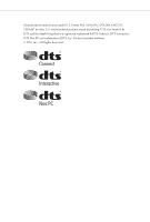
CHA_FAN2 CMOS Z87M Extreme4 Top: Battery 7 USB3_0_1 1 Center: REAR SPK Bottom: Optical SPDIF PCI Express 3.0 1 HD_AUDIO1 Central/Bass LINE IN Top: Center: FRONT Bottom: MIC IN 22 PCIE1 SATA3_0_1 XFast RAM XFast USB Purity SoundTM PCIE2 XFast LAN Intel 8 PCIE3 Z87 64Mb BIOS - ASRock Z87M Extreme4 | Quick Installation Guide - Page 4
12V Power Connector (ATX12V1) 2 CPU Fan Connector (CPU_FAN1) 3 CPU Fan Connector (CPU_FAN2) 4 2 x 240-pin DDR3 DIMM Slots (DDR3_A1, DDR3_B1) 5 2 x 240-pin DDR3 DIMM Slots (DDR3_A2, DDR3_B2) 6 ATX Power Connector (ATXPWR1) 7 USB 3.0 Header (USB3_0_1) 8 SATA3 Connectors (SATA3_0_1) 9 SATA3 Connectors - ASRock Z87M Extreme4 | Quick Installation Guide - Page 5
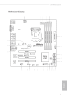
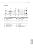
I/O Panel 1 2 Z87M Extreme4 68 3 4 5 79 16 15 No. Description 1 USB 2.0 Ports (USB23) 2 VGA Port 3 USB 3.0 Ports (USB3_45) 4 USB 2.0 Ports (USB01) 5 LAN RJ-45 Port* 6 Central / Bass (Orange) 7 Rear - ASRock Z87M Extreme4 | Quick Installation Guide - Page 6
use the Rear Speaker, Central/Bass, and Front Speaker, or select "Realtek HDA Audio 2nd output" to use the front panel audio. *** The eSATA connector supports SATA3 with cables within 1 meters. English 4 - ASRock Z87M Extreme4 | Quick Installation Guide - Page 7
the latest VGA cards and CPU support list on ASRock's website as well. ASRock website http://www.asrock.com. 1.1 Package Contents • ASRock Z87M Extreme4 Motherboard (Micro ATX Form Factor) • ASRock Z87M Extreme4 Quick Installation Guide • ASRock Z87M Extreme4 Support CD • 4 x Serial ATA (SATA) Data - ASRock Z87M Extreme4 | Quick Installation Guide - Page 8
® / Pentium® / Celeron® in LGA1150 Package • Digi Power Design • 8 Power Phase Design • Supports Intel® Turbo Boost 2.0 Technology • Supports Intel® K-Series unlocked CPU • Supports ASRock BCLK Full-range Overclocking • Intel® Z87 Memory • Dual Channel DDR3 Memory Technology • 4 x DDR3 DIMM slots - ASRock Z87M Extreme4 | Quick Installation Guide - Page 9
Z87M Extreme4 Graphics Audio • Intel® HD Graphics Built-in Visuals and the VGA outputs can be supported only with processors which are GPU integrated. • Supports Intel® HD Graphics Built-in Visuals : Intel® Quick Sync Video with AVC, MVC (S3D) and MPEG-2 Full HW Encode1, Intel® InTruTM 3D, Intel® - ASRock Z87M Extreme4 | Quick Installation Guide - Page 10
Mb/s • Giga PHY Intel® I217V • Supports Intel® Remote Wake Technology • Supports Wake-On-LAN • Supports Energy Efficient Ethernet 802.3az • Supports PXE CPU Fan connectors (1 x 4-pin, 1 x 3-pin) • 2 x Chassis Fan connectors (1 x 4-pin, 1 x 3-pin) • 1 x Power Fan connector (3-pin) • 1 x 24 pin ATX - ASRock Z87M Extreme4 | Quick Installation Guide - Page 11
Z87M Extreme4 BIOS Feature Support CD Hardware Monitor OS Certifications • 1 x 8 pin 12V power connector • 1 x Front panel audio connector • 2 x USB 2.0 headers (support 4 USB 2.0 ports) • 1 x USB 3.0 header (supports 2 USB 3.0 ports) • 64Mb AMI UEFI Legal BIOS with Multilingual GUI support • ACPI - ASRock Z87M Extreme4 | Quick Installation Guide - Page 12
. Due to limitation, the actual memory size may be less than 4GB for the reservation for system usage under Windows® 32-bit operating systems. Windows® 64-bit operating systems do not have such limitations. You can use ASRock XFast RAM to utilize the memory that Windows® cannot use. 10 English - ASRock Z87M Extreme4 | Quick Installation Guide - Page 13
Z87M Extreme4 1.3 Unique Features ASRock A-Tuning A-Tuning is ASRock's multi purpose software suite with a new interface, more new features and improved utilities, including XFast RAM, Dehumidifier, Good Night LED, FAN-Tastic Tuning, OC Tweaker and a whole lot more. ASRock Instant Flash ASRock - ASRock Z87M Extreme4 | Quick Installation Guide - Page 14
of Adobe Photoshop 5 times faster. Another advantage of ASRock XFast RAM is that it reduces the frequency of accessing your SSDs or HDDs in order to extend their lifespan. ASRock Crashless BIOS ASRock Crashless BIOS allows users to update their BIOS without fear of failing. If power loss occurs - ASRock Z87M Extreme4 | Quick Installation Guide - Page 15
Z87M Extreme4 ASRock Easy Driver Installer For users that don't have an optical disk drive to install the drivers from our support CD, Easy Driver Installer is a handy tool in the UEFI that installs the LAN driver ! ASRock Home Cloud This motherboard supports remote wake with the onboard Intel LAN - ASRock Z87M Extreme4 | Quick Installation Guide - Page 16
ASRock FAN-Tastic Tuning ASRock FAN-Tastic Tuning is included in A-Tuning. Configure up to five different fan speeds using the graph. The fans will automatically shift to the next speed level when the assigned temperature is met. 14 English - ASRock Z87M Extreme4 | Quick Installation Guide - Page 17
Z87M Extreme4 Chapter 2 Installation This is an Micro ATX form factor motherboard. Before you install the motherboard, study the configuration of your chassis to ensure that the motherboard fits into it. Pre-installation Precautions Take note of the following precautions before you install - ASRock Z87M Extreme4 | Quick Installation Guide - Page 18
check if the PnP cap is on the socket, if the CPU surface is unclean, or if there are any bent pins in the socket. Do not force to insert the CPU into the socket if above situation is found. Otherwise, the CPU will be seriously damaged. 2. Unplug all power cables before installing - ASRock Z87M Extreme4 | Quick Installation Guide - Page 19
Z87M Extreme4 3 4 5 17 English - ASRock Z87M Extreme4 | Quick Installation Guide - Page 20
Please save and replace the cover if the processor is removed. The cover must be placed if you wish to return the motherboard for after service. 18 English - ASRock Z87M Extreme4 | Quick Installation Guide - Page 21
2.2 Installing the CPU Fan and Heatsink Z87M Extreme4 1 2 CPU_FAN 19 English - ASRock Z87M Extreme4 | Quick Installation Guide - Page 22
Modules (DIMM) This motherboard provides four 240-pin DDR3 (Double Data Rate 3) DIMM slots, and supports Dual Channel Memory Technology. 1. For dual channel configuration, you always need to install identical (the same brand, speed, size and chip-type) DDR3 DIMM pairs. 2. It is unable - ASRock Z87M Extreme4 | Quick Installation Guide - Page 23
Z87M Extreme4 1 2 3 21 English - ASRock Z87M Extreme4 | Quick Installation Guide - Page 24
PCI Express Slots) There are 4 PCI Express slots on the motherboard. Before installing an expansion card, please make sure that the power thermal environment, please connect a chassis fan to the motherboard's chassis fan connector (CHA_FAN1 or CHA_FAN2) when using multiple graphics cards. English - ASRock Z87M Extreme4 | Quick Installation Guide - Page 25
Z87M Extreme4 2.5 Jumpers Setup The illustration shows how jumpers are setup. When the jumper seconds. However, please do not clear the CMOS right after you update the BIOS. If you need to clear the CMOS when you just finish updating the BIOS, you must boot up the system first, and then shut it down - ASRock Z87M Extreme4 | Quick Installation Guide - Page 26
place jumper caps over these headers and connectors. Placing jumper caps over the headers and connectors will cause permanent damage to the motherboard. System Panel Header (9-pin PANEL1) (see p.1, No. 15) PLED+ PLEDPWRBTN# GND 1 GND RESET# GND HDLEDHDLED+ Connect the power switch, reset switch - ASRock Z87M Extreme4 | Quick Installation Guide - Page 27
Z87M Extreme4 SATA3_4_5 SATA3_2_3 SATA3_0_1 Power LED Header (3-pin PLED1) (see p.1, No. 18) 1 PLED- PLED+ PLED+ Serial ATA3 2.0 ports on the I/O panel, there are three headers on this motherboard. Each USB 2.0 header can support two ports. USB 3.0 Headers (19-pin USB3_4_5) (see p.1, No - ASRock Z87M Extreme4 | Quick Installation Guide - Page 28
OUT2_R MIC2_R to the front audio panel. MIC2_L 1 1. High Definition Audio supports Jack Sensing, but the panel wire on the chassis must support HDA to function correctly. Please follow the instructions in our manual and chassis manual to install your system. 2. If you use an AC'97 audio panel - ASRock Z87M Extreme4 | Quick Installation Guide - Page 29
Z87M Extreme4 CPU Fan Connectors (4-pin CPU_FAN1) (see p.1, No. 2) (3-pin CPU_FAN2) (see p.1, No. 3) 4 3 21 GN D + 12V CPU_ FAN_SPEED FAN_SPEED_CONTROL GND +12V CPU_FAN_SPEED This motherboard provides a 4-Pin CPU fan (Quiet Fan) connector. If you plan to connect a 3-Pin CPU fan, please connect it - ASRock Z87M Extreme4 | Quick Installation Guide - Page 30
CI1) (see p.1, No. 20) 1 GND Signal This motherboard supports CASE OPEN detection feature that detects if the chassis cove has GND +3VSB LAD0_L +3V LAD3_L TPM_RST# LFRAME#_L CK_33M_TPM 1 This connector supports Trusted Platform Module (TPM) system, which can securely store keys, digital - ASRock Z87M Extreme4 | Quick Installation Guide - Page 31
VGA-Karten und Prozessoren auf der ASRock-Webseite: ASRock-Webseite http://www.asrock.com. 1.1 Lieferumfang • ASRock Z87M Extreme4-Motherboard (Micro-ATX-Formfaktor) • ASRock Z87M Extreme4-Schnellinstallationsanleitung • ASRock Z87M Extreme4-Support-CD • 4 x Serial-ATA- (SATA) Datenkabel (optional - ASRock Z87M Extreme4 | Quick Installation Guide - Page 32
i3 / Xeon® / Pentium® / Celeron® der 4. Generation im LGA1150-Paket • Digipower-Design • 8-Leistungsphasendesign • Unterstützt Intel® Turbo Boost 2.0-Technologie • Unterstützt CPU mit freiem Multiplikator der Intel® K-Serie • Intel® Z87 Speicher • Dualkanal-DDR3-Speichertechnologie • 4 x DDR3-DIMM - ASRock Z87M Extreme4 | Quick Installation Guide - Page 33
Z87M Extreme4 Grafikkarte Audio • Integrierte Intel® HD Graphics-Visualisierung und VGAAusgänge können nur mit Prozessoren unterstützt werden, die GPU-integriert sind. • Unterstützt integrierte Intel® HD Graphics-Visualisierung: Intel® Quick Sync Video mit AVC, MVC (S3D) und MPEG-2 Full HW Encode1 - ASRock Z87M Extreme4 | Quick Installation Guide - Page 34
Gigabit LAN 10/100/1000 Mb/s • Giga PHY Intel® I217V • Unterstützt Intel® Remote Wake Technology • Unterst 5, RAID 10, Intel Rapid Storage Technology 12 und Intel Smart Response Technology), -Anschluss-Stiftleiste • 1 x Betrieb-LED-Stiftleiste • 2 x CPU-Lüfteranschlüsse (1 x 4-polig, 1 x 3-polig) • - ASRock Z87M Extreme4 | Quick Installation Guide - Page 35
Z87M Extreme4 • 1 x 8-poliger 12-V-Netzanschluss • 1 x Audioanschluss an Frontblende • 2 x USB 2.0-Stiftleisten (unterstützt vier USB 2.0-Ports) • 1 x USB 3.0-Stiftleiste (unterstützt zwei USB 3.0-Ports) BIOS-Funktion • 64-Mb-AMI-UEFI-Legal-BIOS mit Unterstützung mehrsprachiger grafischer - ASRock Z87M Extreme4 | Quick Installation Guide - Page 36
zu der die Anpassung von BIOSEinstellungen, die Anwendung der Untied Overclocking Technology oder die Nutzung von Übertaktungswerkzeugen von Drittanbietern zählen, mit 64 Bit haben keine derartigen Beschränkungen. Mit ASRock XFast RAM können Sie den Speicher einsetzen, den Windows® nicht nutzen - ASRock Z87M Extreme4 | Quick Installation Guide - Page 37
Z87M Extreme4 1.3 Jumpereinstellung Die Abbildung zeigt, wie die Jumper eingestellt werden Sekunden lang mit einer Jumper-Kappe kurz. Löschen Sie den CMOS jedoch nicht direkt nach der BIOS-Aktualisierung. Falls Sie den CMOS direkt nach Abschluss der BIOSAktualisierung löschen müssen, starten Sie das - ASRock Z87M Extreme4 | Quick Installation Guide - Page 38
an diesen Stiftleisten und Anschlüssen an. Durch Anbringen von Jumper-Kappen an diesen Stiftleisten und Anschlüssen können Sie das Motherboard dauerhaft beschädigen. Systemblende-Stiftleiste (9-polig, PANEL1) (siehe S. 1, Nr. 15) PLED+ PLEDPWRBTN# GND 1 GND RESET# GND HDLEDHDLED+ Verbinden Sie - ASRock Z87M Extreme4 | Quick Installation Guide - Page 39
SATA3_4_5 SATA3_2_3 SATA3_0_1 Deutsch Z87M Extreme4 Betrieb-LED-Stiftleiste (3-polig, PLED1) (siehe S. 1, Nr. 18) 1 PLED- PLED+ PLED+ USB 2.0-Ports an der E/A-Blende befinden sich drei Stiftleisten an diesem Motherboard. Jede USB 2.0-Stiftleiste kann zwei Ports unterstützen. USB 3.0-Stiftleisten - ASRock Z87M Extreme4 | Quick Installation Guide - Page 40
Audiostiftleiste (Frontblende) (9-polig, HD_AUDIO1) (siehe S. 1, Nr. 22) GN D PRESENCE# MIC_RET OUT_RET OUT2_L Diese Stiftleiste dient J_SENSE dem Anschließen von OUT2_R MIC2_R Audiogeräten an der MIC2_L 1 Frontblende. 1. High Definition Audio unterstützt Anschlusserkennung, der Draht am - ASRock Z87M Extreme4 | Quick Installation Guide - Page 41
Z87M Extreme4 CPU-Lüfteranschlüsse (4-polig, CPU_FAN1) (siehe S. 1, Nr. 2) (3-polig, CPU_FAN2) (siehe S. 1, Nr. 3) 4 3 21 GN D + 12V CPU_ FAN_SPEED FAN_SPEED_CONTROL GND +12V CPU_FAN_SPEED Dieses Motherboard bietet einen 4-poligen CPULüfteranschluss (lautloser Lüfter). Falls Sie einen 3-poligen - ASRock Z87M Extreme4 | Quick Installation Guide - Page 42
GehäuseeingriffStiftleiste(2-polig, CI1) (siehe S. 1, Nr. 20) 1 GND Signal Dieses Motherboard unterstütztdie Gehäuse-offenErkennung, die erkennt, wenn die Gehäuseabdeckung entfernt wurde. Diese Funktion setzt ein Gehäuse mit Gehäuseeingrifferkennungsdesign voraus. TPM-Stiftleiste ( - ASRock Z87M Extreme4 | Quick Installation Guide - Page 43
disponible sur le site Internet de ASRock. Site Internet ASRock http://www.asrock.com. 1.1 Contenu de l'emballage • Carte mère ASRock Z87M Extreme4 (facteur de forme Micro ATX) • Guide d'installation rapide ASRock Z87M Extreme4 • CD d'assistance ASRock Z87M Extreme4 • 4 x câbles de données Serial - ASRock Z87M Extreme4 | Quick Installation Guide - Page 44
de forme Micro ATX • Condensateur de conception premium or (condensateurs haute qualité en polymère conducteur 100% fabriqués au Japon) Processeur Chipset • Prend en charge les processeurs de 4ème Génération Intel® CoreTM i7 / i5 / i3 / Xeon® / Pentium® / Celeron® en package LGA1150 • Conception - ASRock Z87M Extreme4 | Quick Installation Guide - Page 45
Z87M Extreme4 Graphiques • La technologie Intel® HD Graphics Built-in Visuals et les sorties VGA sont uniquement prises en charge par les processeurs intégrant un contrôleur graphique. • Prend en charge la technologie Intel® HD Graphics Built-in Visuals : Intel® Quick Sync Video avec AVC, MVC (S3D - ASRock Z87M Extreme4 | Quick Installation Guide - Page 46
• Gigabit LAN 10/100/1000 Mb/s • Giga PHY Intel® I217V • Prend en charge la technologie Intel® Remote Wake • Prend en charge ventilateur de châssis (1 x 4 broches, 1 x 3 broches) • 1 x connecteur pour ventilateur d'alimentation (3 broches) • 1 x connecteur d'alimentation ATX 24 broches Français 44 - ASRock Z87M Extreme4 | Quick Installation Guide - Page 47
Z87M Extreme4 • 1 x connecteur d'alimentation 12V 8 broches • 1 x connecteur audio panneau frontal • 2 x embases USB 2.0 (pour 4 ports USB 2.0) • 1 x embase USB 3.0 (pour 2 ports USB 3.0) Caractéristiques du BIOS • BIOS UEFI AMI 64Mo avec prise en charge d'interface graphique multilingue • - ASRock Z87M Extreme4 | Quick Installation Guide - Page 48
risques, incluant des modifications du BIOS, l'application d'une technologie d'overclocking déliée et l'utilisation d'outils d'overclocking développés par des tiers. La Windows® 64-bit. Vous pouvez utiliser ASRock XFast RAM pour utiliser la mémoire dont Windows® ne peut se servir. 46 Français - ASRock Z87M Extreme4 | Quick Installation Guide - Page 49
Z87M Extreme4 1.3 Configuration des cavaliers (jumpers) L'illustration ci-dessous vous renseigne effacez pas la CMOS immédiatement après avoir mis à jour le BIOS. Si vous avez besoin d'effacer les données CMOS après une mise à jour du BIOS, vous devez tout d'abord redémarrer le système, puis l'é - ASRock Z87M Extreme4 | Quick Installation Guide - Page 50
1.4 Embases et connecteurs de la carte mère Les embases et connecteurs situés sur la carte NE SONT PAS des cavaliers. Ne placez JAMAIS de capuchons de cavaliers sur ces embases ou connecteurs. Placer un capuchon de cavalier sur ces embases ou connecteurs endommagera irrémédiablement votre carte mère - ASRock Z87M Extreme4 | Quick Installation Guide - Page 51
SATA3_4_5 SATA3_2_3 SATA3_0_1 Français Z87M Extreme4 Embase LED d'alimentation (PLED1 à 3 broches) (voir p.1, No. 18) 1 PLED- PLED+ PLED+ Connecteurs Serial ATA3 (SATA3_0_1: voir p.1, No. 8) (SATA3_2_3: (voir p.1, No. 9) (SATA3_4_5: (voir p.1, No. 10) Veuillez - ASRock Z87M Extreme4 | Quick Installation Guide - Page 52
être compatible avec la HDA pour fonctionner correctement. Veuillez suivre les instructions figurant dans notre manuel et dans le manuel du châssis pour de les brancher avec le panneau audio AC'97. E. Pour activer le micro frontal, sélectionnez l'onglet « FrontMic » du panneau de contrôle Realtek - ASRock Z87M Extreme4 | Quick Installation Guide - Page 53
Z87M Extreme4 Connecteurs du ventilateur du processeur (CPU_FAN1 à 4 broches) (voir p.1, No. 2) 4 3 21 GN D + 12V un ventilateur de processeur à 3 broches, veuillez le brancher sur la Broche 1-3. Connecteur d'alimentation ATX (ATXPWR1 à 24 broches) (voir p.1, No. 6) 12 24 1 13 Cette carte mè - ASRock Z87M Extreme4 | Quick Installation Guide - Page 54
Embase d'intrusion châssis(CI1 à 2 broches) (voir p.1, No. 20) 1 GND Signal Cette carte mère prend an chargela fonction de détection CHASSIS OUVERT qui alerte l'utilisateur en cas de retrait du boîtier du châssis. Cette fonction requiert un châssis à conception intégrant la détection d'intrusion. - ASRock Z87M Extreme4 | Quick Installation Guide - Page 55
di supporto di CPU anche sul sito Web di ASRock. Sito Web di ASRock http://www.asrock.com. 1.1 Contenuto della confezione • Scheda madre ASRock Z87M Extreme4 (Form Factor Micro ATX) • Guida all'installazione rapida di ASRock Z87M Extreme4 • CD di supporto ASRock Z87M Extreme4 • 4 x cavi dati Serial - ASRock Z87M Extreme4 | Quick Installation Guide - Page 56
Piattaforma • Fattore di forma Micro ATX • Design condensatore Premium Gold (condensatori a conduttore in polimero di alta qualità realizzati al 100% in Giappone) CPU Chipset • Supporta Intel® CoreTM i7 / i5 / i3 di 4^ generazione / Xeon® / Pentium® / Celeron® in LGA1150 Package • Design Digi - ASRock Z87M Extreme4 | Quick Installation Guide - Page 57
Z87M Extreme4 Grafica Audio • La videografica integrata della scheda video HD Intel® e le uscite VGA possono essere supportate soltanto con processori con GPU integrata. • Supporta la videografica integrata della scheda video HD Intel®: Intel® Quick Sync Video con AVC, MVC (S3D) e MPEG-2 Full HW - ASRock Z87M Extreme4 | Quick Installation Guide - Page 58
LAN Gigabit 10/100/1000 Mb/s • Giga PHY Intel® I217V • Supporta la tecnologia Intel® Remote Wake • Supporta Wake RAID 10, Intel Rapid Storage Technology 12 e Intel Smart Response porta COM • 1 x header LED di alimentazione • 2 x connettori ventola CPU (1 x 4 pin, 1 x 3 pin) • 2 x connettori ventola - ASRock Z87M Extreme4 | Quick Installation Guide - Page 59
Z87M Extreme4 • 1 x connettore alimentazione da 12 V a 8 pin • 1 x connettore audio pannello anteriore • 2 x header USB 2.0 (supporto 4 porte USB 2.0) • 1 x header USB 3.0 (supporta 2 porte USB 3.0) Caratteristiche del BIOS • BIOS legale 64 Mb AMI UEFI con supporto GUI multilingue • Eventi di - ASRock Z87M Extreme4 | Quick Installation Guide - Page 60
overclocking, inclusa la regolazione delle impostazioni nel BIOS, l'applicazione di tecnologia di Untied Overclocking o l'utilizzo di strumenti di overclocking di terze parti. L'overclocking . È possibile utilizzare la RAM XFast di ASRock per utilizzare la memoria che Windows® non può - ASRock Z87M Extreme4 | Quick Installation Guide - Page 61
Z87M Extreme4 1.3 Impostazione jumper L'illustrazione mostra in che modo vengono impostati i jumper. Tuttavia, non azzerare la CMOS subito dopo aver aggiornato il BIOS. Se è necessario azzerare la CMOS dopo l'aggiornamento del BIOS, è necessario riavviare prima il sistema e in seguito spegnerlo - ASRock Z87M Extreme4 | Quick Installation Guide - Page 62
1.4 Header e connettori sulla scheda Gli header e i connettori sulla scheda NON sono jumper. NON posizionare cappucci del jumper su questi header e connettori. Il posizionamento di cappucci del jumper su header e connettori provocherà danni permanenti alla scheda madre. Header sul pannello del - ASRock Z87M Extreme4 | Quick Installation Guide - Page 63
SATA3_4_5 SATA3_2_3 SATA3_0_1 Italiano Z87M Extreme4 Header LED di alimentazione (PLED1 a 3 pin) (vedere pag. 1, n. 18) Connettori Serial ATA3 (SATA3_0_1: vedere pag.1,n. 8) (SATA3_2_3: vedere pag. 1, n. 9) (SATA3_4_5: vedere pag. 1, n. 10) 1 PLED- PLED+ PLED+ - ASRock Z87M Extreme4 | Quick Installation Guide - Page 64
Jack sensing, ma il filo del pannello sullo chassis deve supportare HDA per funzionare correttamente. Seguire le istruzioni presenti nel nostro manuale e nel manuale dello chassis per installare il sistema. 2. Se si utilizza un pannello audio AC'97, installarlo sull'header audio del pannello - ASRock Z87M Extreme4 | Quick Installation Guide - Page 65
Z87M Extreme4 Connettori della ventola della CPU (CPU_FAN1 a 4 pin) (vedere pag. 1, n. 2) 4 3 21 GN D + 12V CPU_ FAN_SPEED FAN_SPEED_CONTROL (CPU_FAN2 a 3 pin) (vedere pag. 1, n. 3) GND +12V CPU_FAN_SPEED Questa scheda madre è dotata di un connettore per la ventola della CPU (Ventola silenziosa - ASRock Z87M Extreme4 | Quick Installation Guide - Page 66
Header di intrusione nello chassis(CI1 a 2 pin) (vedere pag. 1, n. 20) 1 GND Signal Questa scheda madre supportala caratteristica di rilevamento CASE OPEN che rileva che il coperchio del case è stato rimosso. Questa funzione richiede uno chassis con caratteristiche di rilevamento di intrusione - ASRock Z87M Extreme4 | Quick Installation Guide - Page 67
de compatibilidad de la CPU, en el sitio web de ASRock. Sitio web de ASRock http://www.asrock.com. 1.1 Contenido del paquete • Placa base ASRock Z87M Extreme4 (Factor de forma Micro ATX) • Guía de instalación rápida de ASRock Z87M Extreme4 • CD de soporte de ASRock Z87M Extreme4 • 4 cables de datos - ASRock Z87M Extreme4 | Quick Installation Guide - Page 68
• Factor de forma Micro ATX • Diseño de los Condensadores: Premium Gold (Condensadores de polímero conductor, de alta calidad, 100% fabricados en Japón) CPU • Compatible con 4.ª Generación de Intel® CoreTM i7 / i5 / i3 / Xeon® / Pentium® / Celeron® en Paquete LGA1150 • Diseño Digi Power - ASRock Z87M Extreme4 | Quick Installation Guide - Page 69
Z87M Extreme4 Gráficos Audio • La Tecnología visual integrada de gráficos HD de Intel® y las salidas de VGA son compatibles únicamente con procesadores con GPU integrado. • Compatible con la Tecnología visual integrada de gráficos HD de Intel®: Intel® Quick Sync Video con AVC, MVC (S3D) y MPEG-2 - ASRock Z87M Extreme4 | Quick Installation Guide - Page 70
Mb/s • Giga PHY Intel® I217V • Compatible con la Tecnología Remote Wake de Intel® Tecnología Rapid Storage 12 de Intel y Tecnología Smart Response de Intel), NCQ, AHCI y funciones de indicador LED de alimentación • 2 conectores de ventilador de la CPU (1 de 4 pines y 1 de 3 pines) • 2 conectores - ASRock Z87M Extreme4 | Quick Installation Guide - Page 71
Z87M Extreme4 • 1 conector de alimentación de 12V de 8 pines • 1 conector de audio del panel frontal • 2 cabezales USB 2.0 (compatibles con 4 puertos USB 2.0) • 1 cabezal USB 3.0 (compatible con 2 puertos USB 3.0) Características del BIOS • BIOS legal UEFI AMI de 64Mb compatible con interfaz grá - ASRock Z87M Extreme4 | Quick Installation Guide - Page 72
el overclocking. Debido a las limitaciones, el tamaño real de la memoria podrá ser inferior a 4GB para reservar espacio para el uso del sistema en sistemas operativos Windows® de 32 bits. Los sitemas operativos Windows® de 64 bits no tienen estas limitaciones. Podrá utilizar XFast RAM de ASRock para - ASRock Z87M Extreme4 | Quick Installation Guide - Page 73
Z87M Extreme4 1.3 Instalación de los puentes La instalación muestra cómo deben embargo, no borre el CMOS justo después de que haya actualizado el BIOS. Si necesita borrar el CMOS cuando acabe de actualizar el BIOS, deberá arrancar el sistema primero y, a continuación, deberá apagarlo antes - ASRock Z87M Extreme4 | Quick Installation Guide - Page 74
1.4 Conectores y cabezales incorporados Los cabezales y conectores incorporados NO son puentes. NO coloque tapas de puente sobre estos cabezales y conectores. Si coloca tapas de puente sobre los cabezales y conectores dañará de forma permanente la placa base. Cabezal del panel del sistema (PANEL1 - ASRock Z87M Extreme4 | Quick Installation Guide - Page 75
SATA3_4_5 SATA3_2_3 SATA3_0_1 Español Z87M Extreme4 Cabezal de indicador LED de alimentación (PLED1 de 3 pines) (consulte la pág.1, N.º 18) 1 PLED- PLED+ PLED+ Conectores Serie ATA3 (SATA3_0_1: consulte la pág.1, N.º 8) (SATA3_2_3: consulte la pág.1, N.º 9) (SATA3_4_5: - ASRock Z87M Extreme4 | Quick Installation Guide - Page 76
, el cable del panel del chasis deberá ser compatible con HDA para que pueda funcionar correctamente. Siga las instrucciones que se indican en nuestro manual y en el manual del chasis para instalar su sistema. 2. Si utiliza un panel de audio AC'97, colóquelo en el cabezal de audio del panel frontal - ASRock Z87M Extreme4 | Quick Installation Guide - Page 77
Z87M Extreme4 Conectores del ventilador de la CPU (CPU_FAN1 de 4 pines) (consulte la pág.1, N.º 2) 4 3 21 GN D + 12V 1) 4 Esta placa base contiene un 5 conector de alimentación ATX de 12V y 8 pines. 1 Para utilizar una toma de alimentación ATX de 4 pines, conéctela en los Pines del 1 al 5. - ASRock Z87M Extreme4 | Quick Installation Guide - Page 78
Cabezal de intrusión de chasis(CI1 de 2 pines) (consulte la pág.1, N.º 20) 1 GND Signal Esta placa base es compatible conla función de detección de CUBIERTA ABIERTA que detecta si se ha retirado la cubierta del chasis. Esta función requiere un chasis diseñado para la detección de intrusión del - ASRock Z87M Extreme4 | Quick Installation Guide - Page 79
Z87M Extreme4 1 ASRock Z87M Extreme4 ASRock ASRock BIOS ASRock ASRock VGA ASRock http://www.asrock.com. 1.1 ASRock Z87M Extreme4 Micro ATX ASRock Z87M Extreme4 ASRock Z87M Extreme4 • 4 Serial ATA (SATA 1 1 x ASRock SLI_Bridge_Card 77 - ASRock Z87M Extreme4 | Quick Installation Guide - Page 80
1.2 Micro ATX Premium Gold Capacitor 4 Intel® CoreTM i7 / i5 / i3 / Xeon® / Pentium® / Celeron LGA1150 • Digi Power Design 8 Intel® Turbo Boost 2.0 Intel K • Intel® Z87 Память DDR3 • 4 DDR3 DIMM DDR3 2800+(OC)/2400(OC)/ 2133(OC)/1866(OC)/1600/1333/1066 Non-ECC - ASRock Z87M Extreme4 | Quick Installation Guide - Page 81
Z87M Extreme4 Intel® HD Graphics Builtin Visuals и VGA Intel® HD Graphics: Intel® Quick Sync Video с AVC, MVC (S3D) и MPEG-2 Full HW Encode1, Intel® InTruTM 3D, Intel® Clear Video HD Technology, Intel® InsiderTM, Intel® HD Graphics 4400/4600 • Pixel Shader 5.0, DirectX 11.1 1792 VGA: - ASRock Z87M Extreme4 | Quick Installation Guide - Page 82
• 1 x eSATA • 4 x USB 2.0 • 4 x USB 3.0 • 1 x RJ-45 ACT/LINK и МИД SPEED HD Audio • 6 x SATA3 6,0 RAID (RAID 0, RAID 1, RAID 5, RAID 10, Intel Rapid Storage Technology 12 и Intel Smart Response Technology NCQ, AHCI SATA3_1 eSATA) • 1 x eSATA NCQ, AHCI • 1 x 1 x 1 x IR - ASRock Z87M Extreme4 | Quick Installation Guide - Page 83
Z87M Extreme4 • 1 x 8 12 В • 1 x 2 x USB 2.0 4 USB 2.0) • 1 x USB 3.0 2 USB 3.0) BIOS • 64 Мб AMI UEFI Legal BIOS ACPI 1.1 SMBIOS 2.3.1 DRAM, PCH 1,05 В, PCH 1,5 В CyberLink MediaEspresso 6.5 Google Chrome, Start8, MeshCentral, Splashtop Streamer, Intel® Extreme Tuning - ASRock Z87M Extreme4 | Quick Installation Guide - Page 84
BIOS Untied Overclocking Technology 32 Windows 4 64 Windows Windows ASRock XFast RAM. 82 - ASRock Z87M Extreme4 | Quick Installation Guide - Page 85
Z87M Extreme4 1.3 3 1 и 2 CMOS (CLRCMOS1 1, № 12) CMOS CLRCMOS1 CMOS 15 2 и 3 на CLRCMOS1 на 5 CMOS BIOS CMOS BIOS CMOS CMOS. 1 CMOS CMOS. 2 CMOS Clear Status BIOS. 83 - ASRock Z87M Extreme4 | Quick Installation Guide - Page 86
1.4 9 PANEL1 1, № 15) PLED+ PLEDPWRBTN# GND 1 GND RESET# GND HDLEDHDLED+ PWRBTN RESET PLED S1/S3 S4 S5 HDLED 84 - ASRock Z87M Extreme4 | Quick Installation Guide - Page 87
SATA3_4_5 SATA3_2_3 SATA3_0_1 Z87M Extreme4 3 PLED1 1, № 18) 1 PLED- PLED+ PLED+ Serial ATA3 (SATA3_0_1 1, № 8) (SATA3_2_3 1, № 9) (SATA3_4_5 1, № 10) SATA3 SATA 6,0 eSATA SATA3_1 USB 2.0. (9 USB4_5 1, № 17) (9 USB6_7 1, № 18) USB_PWR PP+ GND DUMMY 1 GND P+ - ASRock Z87M Extreme4 | Quick Installation Guide - Page 88
9 HD_ AUDIO1 1, № 22) GN D PRESENCE# MIC_RET OUT_RET OUT2_L J_SENSE OUT2_R MIC2_R MIC2_L 1 1 HDA 2 AC'97 A Mic_IN (MIC) к MIC2_L. B Audio_R (RIN) к OUT2_R, Audio_L (LIN) к OUT2_L. C GND GND). D MIC_RET и OUT_RET AC'97 E FrontMic Realtek Recording Volume - ASRock Z87M Extreme4 | Quick Installation Guide - Page 89
Z87M Extreme4 4 CPU_ FAN1 1, № 2) 4 3 21 GN D + 12V CPU_ FAN_SPEED FAN_SPEED_CONTROL (3 CPU_ FAN2 1, № 3) GND +12V CPU_FAN_SPEED 24 ATXPWR1 1, № 6) 12 24 1 13 12 В 8 5 (8 ATX12V1 1, № 1) 4 1 5 IR1 1, № 14) IRTX +5VSB DUMMY 1 GND IRRX 4 3 1-3. 24 20 ATX - ASRock Z87M Extreme4 | Quick Installation Guide - Page 90
2 CI1 1, № 20) 1 GND Signal 17 TPMS1 1, № 19) F_CLKRUN# SERIRQ# S_PWRDWN# GND LAD1_L LAD2_L SMB_DATA_MAIN SMB_CLK_MAIN GND GND +3VSB Trusted LAD0_L Platform Module (TPM +3V LAD3_L TPM_RST LFRAME#_L CK_33M_TPM 1 88 - ASRock Z87M Extreme4 | Quick Installation Guide - Page 91
placas VGA e CPU mais recentes suportadas no Web site da ASRock. Web site da ASRock http://www.asrock.com. 1.1 Conteúdo da embalagem • Placa principal ASRock Z87M Extreme4 (Formato Micro ATX) • Guia de instalação rápida do ASRock Z87M Extreme4 • CD de suporte do ASRock Z87M Extreme4 • 4 x Cabos de - ASRock Z87M Extreme4 | Quick Installation Guide - Page 92
• Formato Micro ATX • Design de condensadores banhados a ouro de alta qualidade (Condensadores de polímeros condutores de alta qualidade 100% fabricados no Japão) CPU • Suporta processadores Intel® CoreTM i7 / i5 / i3 / Xeon® / Pentium® / Celeron® de 4ª geração em socket LGA1150 • Design - ASRock Z87M Extreme4 | Quick Installation Guide - Page 93
Z87M Extreme4 Gráficos Áudio • Os gráficos incorporados Intel® HD e as saídas VGA apenas podem ser suportados com processadores com GPU integrada. • Suporta gráficos incorporados Intel® HD: Intel® Quick Sync Video com AVC, MVC (S3D) e MPEG-2 Full HW Encode1, Intel® InTruTM 3D, Tecnologia Intel® - ASRock Z87M Extreme4 | Quick Installation Guide - Page 94
a 10/100/1000 Mb/s • Giga PHY Intel® I217V • Suporta tecnologia Intel® Remote Wake • Suporta 5, RAID 10, tecnologia Intel Rapid Storage 12 e tecnologia Intel Smart Response), NCQ, 1 x Conector para LED de alimentação • 2 x Conectores da ventoinha da CPU (1 x 4 pinos, 1 x 3 pinos) • 2 x Conectores da - ASRock Z87M Extreme4 | Quick Installation Guide - Page 95
Z87M Extreme4 • 1 x conector de alimentação de 12V de 8 pinos • 1 x conector de áudio do painel frontal • 2 x terminais USB 2.0 (suporte para 4 portas USB 2.0) • 1 x terminal USB 3.0 (suporte para 2 portas USB 3.0) Funcionalidades do BIOS • BIOS UEFI oficial da AMI com 64Mb com suporte de - ASRock Z87M Extreme4 | Quick Installation Guide - Page 96
possíveis danos causados pelo overclocking. Devido às limitações, o tamanho real da memória de 4GB reservada para utilização em sistemas operativos Windows® 32-bits poderá ser inferior. Os sistemas operativos Windows® 64bits não possuem essas limitações. Pode utilizar o ASRock XFast RAM para dar uso - ASRock Z87M Extreme4 | Quick Installation Guide - Page 97
Z87M Extreme4 1.3 Configuração dos jumpers A imagem abaixo ilustra como os jumpers são configurados. limpe o CMOS logo após ter efectuado a actualização da BIOS. Se precisar de limpar o CMOS logo após ter terminado uma actualização da BIOS, deverá primeiro iniciar o sistema e voltar a encerrá-lo - ASRock Z87M Extreme4 | Quick Installation Guide - Page 98
1.4 Terminais e conectores integrados Os terminais e conectores integrados NÃO são jumpers. NÃO coloque tampas de jumpers sobre estes terminais e conectores. Colocar tampas de jumpers sobre os terminais e conectores irá causar danos permanentes à placa principal. Terminal do painel de sistema ( - ASRock Z87M Extreme4 | Quick Installation Guide - Page 99
SATA3_4_5 SATA3_2_3 SATA3_0_1 Português Z87M Extreme4 Conector do LED de alimentação (PLED1 de 3 pinos) (consultar p.1, N.º 18) 1 PLED- PLED+ PLED+ Conectores ATA3 de série (SATA3_0_1: consultar p.1, N.º 8) (SATA3_2_3: consultar p.1, N.º 9) (SATA3_4_5: consultar p.1, N.º 10) Ligue o - ASRock Z87M Extreme4 | Quick Installation Guide - Page 100
definição suporta Detecção de ficha, mas o cabo de painel no chassis deverá suportar HDA para funcionar correctamente. Siga as instruções no nosso manual e no manual do chassis para instalar o seu sistema. 2. Se utilizar um painel de áudio AC'97, instale-o no terminal de áudio do painel frontal de - ASRock Z87M Extreme4 | Quick Installation Guide - Page 101
Z87M Extreme4 Português Conectores da ventoinha da CPU (CPU_FAN1 de 4 pinos) (consultar p.1, N.º 2) (CPU_FAN2 de 3 pinos) (consultar p.1, N.º 3) 4 3 21 GN D + 12V CPU_ FAN_SPEED FAN_SPEED_CONTROL GND +12V CPU_FAN_SPEED Esta placa principal inclui um conector de ventoinha de CPU (Ventoinha - ASRock Z87M Extreme4 | Quick Installation Guide - Page 102
Terminal de intrusão do chassis(CI1 de 2 pinos) (consultar p.1, N.º 20) 1 GND Signal Esta placa principal suportaa função de detecção de ABERTURA da CAIXA que detecta se a tampa do chassis foi removida. Esta função requer um chassis com design de detecção de intrusão. Terminal TPM (TPMS1 de 17 - ASRock Z87M Extreme4 | Quick Installation Guide - Page 103
güncel VGA kartları ve CPU destek listelerini de ASRock'ın web sitesinden bulabilirsiniz. ASRock web sitesi http://www.asrock.com. 1.1 Ambalaj İçeriği • ASRock Z87M Extreme4 Anakartı (Micro ATX Form Faktörü) • ASRock Z87M Extreme4 Hızlı Kurulum Kılavuzu • ASRock Z87M Extreme4 Destek CD'si • 4 x Seri - ASRock Z87M Extreme4 | Quick Installation Guide - Page 104
Platform • Micro ATX Form Faktörü • Premium Gold Sığa tasarımı (%100 Japon-malı kaliteli İletken Polimer Sığalar) CPU • 4ncü Nesil Intel® CoreTM i7 / i5 / i3 / Xeon® / Pentium® / Celeron®, LGA1150 Paketinde desteklemektedir • Dijital Güç Tasarımı • 8 Güç Safhası Tasarımı • Intel® Turbo Boost - ASRock Z87M Extreme4 | Quick Installation Guide - Page 105
Z87M Extreme4 Grafikler Ses • Intel® HD Graphics Dahili Görselleri ile VGA çıktıları, yalnızca GPU entegre edilmiş işlemciler ile desteklenir. • Intel® HD Graphics Dahili Görsellerini destekler : AVC, MVC (S3D) ve MPEG-2 Full HW Encode1, Intel® InTruTM 3D, Intel® Net Video HD Teknolojisi, Intel® - ASRock Z87M Extreme4 | Quick Installation Guide - Page 106
1000 Mb/s • Giga PHY Intel® I217V • Intel® RAID 1, RAID 5, RAID 10, Intel Hızlı Depolama Teknolojisi 12 ve Intel Akıllı Yanıt Teknolojisi), NCQ, lantısı • 1 x COM Bağlantı noktası bağlantısı • 1 x Güç LED bağlantısı • 2 x CPU Fan bağlayıcıları (1 x 4-pin, 1 x 3-pin) • 2 x Kasa Fanı konektörü (1 x 4- - ASRock Z87M Extreme4 | Quick Installation Guide - Page 107
Z87M Extreme4 • 1 x 8 pin 12V güç bağlayıcısı • 1 x Ön panel ses bağlayıcısı • 2 x USB 2.0 bağlantısı (4 USB 2.0 bağlantı noktasını destekler) • 1 x USB 3.0 bağlantısı (2 USB 3.0 bağlantı noktasını destekler) BIOS Özelliği • Çok dilli GUI Desteği ile 64Mb AMI UEFI Legal BIOS • ACPI 1.1 Uyumluluğu - ASRock Z87M Extreme4 | Quick Installation Guide - Page 108
Türkçe Lütfen, BIOS ayarlarını düzenleme, Bağımsız Hız Aşırtma Teknolojinin uygulanması ya da üçüncü kişilerin hız aşırtma araçlarının kullanı -bit işletim sistemlerinde bu tür sınırlamalar yoktur. Windows® tarafından kullanılmayan bellekten faydalanmak için ASRock XFast RAM'i kullanabilirsiniz. 106 - ASRock Z87M Extreme4 | Quick Installation Guide - Page 109
Z87M Extreme4 1.3 Bağlantı Teli Kurulumu Çizim, bağlantı tellerinin kurulumunu göstermektedir. Tel kısaltmak için bir bağlantı teli kullanın. Ancak, CMOS'u lütfen BIOS'u güncelledikten hemen sonra temizlemeyin. BIOS'u güncelledikten hemen sonra CMOS'u temizlemeniz gerekirse, önce sistemi başlatın - ASRock Z87M Extreme4 | Quick Installation Guide - Page 110
1.4 Ekli Bağlantılar ve Bağlayıcılar Ekli bağlantılar ve bağlayıcılar bağlantı teli değildir. Bağlantı teli kapaklarını bu bağlantı ve bağlayıcılar üzerine yerleştirmeyin. Bağlantı teli kapaklarının bağlantılar ile bağlayıcılar üzerine yerleştirilmesi, anakarta kalıcı hasar verebilir. Sistem Paneli - ASRock Z87M Extreme4 | Quick Installation Guide - Page 111
SATA3_4_5 SATA3_2_3 SATA3_0_1 Türkçe Z87M Extreme4 Güç LED Bağlantısı (3-pin PLED1) (bkz. sf.1, No. 18) Seri ATA3 Bağlayıcıları (SATA3_0_1: bkz. sf.1, No. 8) (SATA3_2_3: bkz. sf.1, No. 9) (SATA3_4_5: bkz. sf.1, - ASRock Z87M Extreme4 | Quick Installation Guide - Page 112
Ön Panel Ses Bağlantısı (9-pin HD_AUDIO1) (bkz. sf.1, No. 22) GN D PRESENCE# MIC_RET OUT_RET OUT2_L Bu bağlantı, ses aygıtlarının J_SENSE ön ses paneline bağlanması OUT2_R MIC2_R içindir. MIC2_L 1 1. Yüksek Tanımlı Ses, Jak Algılama özelliğini destekler, ancak bu işlevin düzgün çalış - ASRock Z87M Extreme4 | Quick Installation Guide - Page 113
Z87M Extreme4 CPU Fan Bağlayıcıları (4-pin CPU_FAN1) (bkz sf.1, No. 2) (3-pin CPU_FAN2) (bkz sf.1, No. 3) 4 3 21 GN D + 12V CPU_ FAN_SPEED FAN_SPEED_CONTROL GND +12V CPU_FAN_SPEED Bu anakart, 4-Pin CPU fan (Sessiz Fan) bağlayıcısı sağlamaktadır. 3-Pin CPU fan bağlamak istiyorsanız, lütfen Pin - ASRock Z87M Extreme4 | Quick Installation Guide - Page 114
Kasa Yetkisiz Erişim Bağlantısı(2-pin CI1) (bkz. sf.1, No. 20) 1 GND Signal Bu anakartkasa kapağının açılıp açılmadığını tespit eden bir KASA AÇIK özelliği bulunmaktadır. Bu özelliğin kullanılabilmesi için kasa yetkisiz erişim tasarımına sahip bir kasa kullanılmalıdır. TPM bağlantısı (17-pin - ASRock Z87M Extreme4 | Quick Installation Guide - Page 115
한국어 Z87M Extreme4 1 개요 ASRock Z87M Extreme4 ASRock ASRock BIOS ASRock ASRock VGA 카드와 CPU ASRock http://www.asrock.com. 1.1 • ASRock Z87M Extreme4 Micro ATX ASRock Z87M Extreme4 ASRock Z87M Extreme4 지원 CD ATA (SATA 4 I/O 1 개 • 1 x ASRock SLI_Bridge_Card 113 - ASRock Z87M Extreme4 | Quick Installation Guide - Page 116
규격 플랫폼 CPU • Micro ATX 100 • LGA1150 4 세대 Intel® CoreTM i7 / i5 / i3 / Xeon® / Pentium® / Celeron® 지원 • Digi 8 Intel® Turbo Boost 2.0 Intel®K CPU 지원 • Intel® Z87 DDR3 DDR3 DIMM 슬롯 4 개 • DDR3 2800+(OC)/2400(OC)/2133(OC)/1866 (OC)/1600/1333/1066 비 -ECC 32GB Intel® Extreme Memory - ASRock Z87M Extreme4 | Quick Installation Guide - Page 117
Z87M Extreme4 • Intel® HD VGA 출력은 GPU • Intel® HD AVC, MVC (S3D) 및 MPEG-2 풀 HW Encode1 지원 Intel® Quick Sync Video, Intel® InTruTM 3D, Intel HD 기술 , Intel® InsiderTM, Intel® HD 4400/4600 • Pixel Shader 5.0, DirectX 11.1 1792MB • VGA D-Sub, DVI-D 및 HDMI HDMI 4K × 2K (4096x2304) @ 24Hz) - ASRock Z87M Extreme4 | Quick Installation Guide - Page 118
• Gigabit LAN 10/100/1000 Mb/s • Giga PHY Intel® I217V • Intel • Wake-On-LAN 지원 802 Intel 12 및 Intel NCQ, AHCI SATA3_1 eSATA • eSATA 커넥터 1 개 , NCQ, AHCI 커넥터 1 개 • TPM 헤더 1 개 • IR 헤더 1 개 • COM 1 LED 헤더 1 개 • CPU 2 개 (1 x 4 핀 , 1 x 3 2 개 (1 x 4 핀 , 1 x 3 1 개 (3 핀 ) • 24 핀 ATX - ASRock Z87M Extreme4 | Quick Installation Guide - Page 119
Z87M Extreme4 • 8 핀 12V 1 1 개 • USB 2.0 헤더 2 개 (USB 2.0 포트 4 USB 3.0 헤더 1 개 (USB 3.0 포트 2 BIOS 기능 GUI 64Mb AMI UEFI 적합형 BIOS • ACPI 1.1 SMBIOS 2.3.1 지원 • CPU, DRAM, PCH 1.05V, PCH 1.5V 지원 CD CyberLink MediaEspresso 6.5 Google Chrome Start8, MeshCentral, Splashtop Streamer, Intel® - ASRock Z87M Extreme4 | Quick Installation Guide - Page 120
한 국 어 BIOS Untied Overclocking Technology Windows® 32 4GB Windows® 64 ASRock XFast RAM Windows 118 - ASRock Z87M Extreme4 | Quick Installation Guide - Page 121
Z87M Extreme4 1.3 3 1 과 핀 2 Clear CMOS 점퍼 (CLRCMOS1) (1 12 기본값 Clear CMOS CLRCMOS1 CMOS 15 CLRCMOS1 의 핀 2 와 핀 3 을 5 BIOS CMOS BIOS CMOS CMOS CMOS 1. Clear CMOS Clear CMOS 2. CMOS BIOS 옵션 "Clear Status 한국어 119 - ASRock Z87M Extreme4 | Quick Installation Guide - Page 122
한 국 어 1.4 (9 핀 PANEL1) (1 15 PLED+ PLEDPWRBTN# GND 1 GND RESET# GND HDLEDHDLED+ PWRBTN RESET PLED LED LED S1/S3 LED S4 S5 LED HDLED LED LED LED LED LED 120 - ASRock Z87M Extreme4 | Quick Installation Guide - Page 123
SATA3_4_5 SATA3_2_3 SATA3_0_1 한국어 Z87M Extreme4 전원 LED 헤더 (3 핀 PLED1) (1 18 시리얼 ATA3 커넥터 (SATA3_0_1: 1 8 SATA3_2_3: (1 9 SATA3_4_5: (1 10 1 PLED- PLED+ PLED+ LED 이들 6 개의 SATA3 6.0 Gb/s SATA I/O 의 eSATA SATA3_1 USB 2.0 헤더 (9 핀 USB4_5) (1 17 9 핀 USB6_7) (1 18 USB_PWR PP+ - ASRock Z87M Extreme4 | Quick Installation Guide - Page 124
(9 핀 HD_AUDIO1) (1 22 GN D PRESENCE# MIC_RET OUT_RET OUT2_L J_SENSE OUT2_R MIC2_R MIC2_L 1 1 HDA 2. AC'97 A. Mic_IN (MIC) 를 MIC2_L B. Audio_R (RIN) 을 OUT2_R Audio_L (LIN) 을 OUT2_L C. 접지 (GND GND D. MIC_RET 및 OUT_RET 는 HD AC'97 E Realtek FrontMic Recording - ASRock Z87M Extreme4 | Quick Installation Guide - Page 125
Z87M Extreme4 한국어 CPU 4 핀 CPU_FAN1) (1 2 4 3 21 GN D + 12V CPU_ FAN_SPEED FAN_SPEED_CONTROL (3 핀 CPU_FAN2) (1 3 GND +12V CPU_FAN_SPEED 4 핀 CPU 3 핀 CPU 경우 핀 1-3 ATX 24 핀 ATXPWR1) (1 6 12 24 1 13 24 핀 ATX 20 핀 ATX 1 과 핀 13 ATX 12V 8 핀 ATX12V1) (1 1 5 핀 IR1 - ASRock Z87M Extreme4 | Quick Installation Guide - Page 126
2 핀 CI1) (1 20 1 GND Signal TPM 헤더 (17 핀 TPMS1) (1 19 F_CLKRUN# SERIRQ# S_PWRDWN# GND LAD1_L LAD2_L SMB_DATA_MAIN SMB_CLK_MAIN GND GND +3VSB LAD0_L +3V LAD3_L TPM_RST# LFRAME#_L CK_33M_TPM 1 TPM(Trusted Platform Module TPM 한 국 어 124 - ASRock Z87M Extreme4 | Quick Installation Guide - Page 127
日本語 Z87M Extreme4 1 ͡Ίʹ ASRock Z87M Extreme4 BIOS VGA CPU http://www.asrock.com. 1.1 • ASRock Z87M Extreme4 ATX ASRock Z87M Extreme4 ASRock Z87M Extreme4 αϙʔτ CD • 4 x γϦΞϧ ATAʢSATA 1 x I/O 1 x ASRock SLI_Bridge_Card 125 - ASRock Z87M Extreme4 | Quick Installation Guide - Page 128
日本語 1.2 仕様 ATX 100 CPU • LGA1150 4 ੈͷ Intel® CoreTM i7 / i5 / i3 / Xeon® / Pentium® / Celeron 8 Intel 2.0 Intel®K CPU Λαϙʔτ • Intel® Z87 ϝϞϦ DDR3 4 x DDR3 DIMM DDR3 2800+(OC)/2400(OC)/2133(OC)/1866(OC)/ 1600/1333/1066 ECC 32GB Intel XMPʣ1.3/1.2 Λ αϙʔτ • 2 x - ASRock Z87M Extreme4 | Quick Installation Guide - Page 129
日本語 Z87M Extreme4 • Intel®HD VGA ग़ྗɺ GPU • Intel®HD AVCɺ MVC (S3D)ɺMPEG-2 ϑϧ HW Τϯίʔυ 1 ͷ Intel® Quick Sync VideoɺIntel® InTruTM 3DɺIntel HD Intel TMɺIntel® HD 4400/4600 • Pixel Shader 5.0, DirectX 11.1 1792MB • 3 ͭͷ VGA D-SubɺDVI-DɺHDMI • 3 HDMI 4K ʷ 2K ʢ4096x2304ʣ@24Hz • DVI-D - ASRock Z87M Extreme4 | Quick Installation Guide - Page 130
日本語 LAN LAN 10/100/1000 Mb PHY Intel® I217V • Intel 802.3az PXE Λαϙʔτ ϦΞύωϧ I/O • 1 x PS Intel 12ɺ Intel NCQɺAHCI SATA3_1 eSATA • 1 x eSATA NCQɺAHCI ίωΫλʔ • 1 x 1 x TPM 1 x IR 1 x COM 1 x LED 2 x CPU 1 x 4 ϐϯɺ1 x 3 ϐϯʣ • 2 x 1 x 4 ϐϯɺ1 x 3 ϐϯʣ • 1 x 3 ϐϯʣ • 1 x 24 ϐϯ ATX - ASRock Z87M Extreme4 | Quick Installation Guide - Page 131
Z87M Extreme4 • 1 x 8 ϐϯ 12V 1 x 2 x USB 2.0 ϔομʔʢ4 ͭͷ USB 2.0 1 x USB 3.0 ϔομʔʢ2 ͭͷ USB 3.0 BIOS ػೳ GUI 64Mb AMI UEFI Legal BIOS • ACPI 1.1 SMBIOS 2.3.1 CPUɺDRAMɺPCH 1.05VɺPCH 1.5V αϙʔτ CD CyberLink MediaEspresso 6.5 Google Chrome Start8ɺ MeshCentralɺSplashtop StreamerɺIntel - ASRock Z87M Extreme4 | Quick Installation Guide - Page 132
日本語 BIOS Windows® 32 4GB Windows® 64 Windows ASRock XFast RAM 130 - ASRock Z87M Extreme4 | Quick Installation Guide - Page 133
日本語 Z87M Extreme4 1.3 3 1 ͱϐϯ 2 CMOS CLRCMOS1) ʢp.1ɺNo. 12 ࢀরʣ σϑΥϧτ CMOS ͷΫϦΞ CLRCMOS1 ɺCMOS 15 CLRCMOS1 ͷϐ ϯ 2 ͱϐϯ 3 5 BIOS CMOS BIOS CMOS CMOS CMOS 1. CMOS CMOS 2. CMOS BIOS Clear Statuʢs 131 - ASRock Z87M Extreme4 | Quick Installation Guide - Page 134
日本語 1.4 9 ϐϯύωϧ 1ʣ ʢp.1ɺNo. 15 ࢀরʣ PLED+ PLEDPWRBTN# GND 1 GND RESET# GND HDLEDHDLED+ PWRBTN RESET PLED LED LED S1/S3 LED S4 S5 LED HDLED LED LED LED LED LED 132 - ASRock Z87M Extreme4 | Quick Installation Guide - Page 135
SATA3_4_5 SATA3_2_3 SATA3_0_1 日本語 Z87M Extreme4 ి ݯLED ϔομʔ ʢ3 ϐϯ PLED1ʣ ʢp.1ɺNo. 18 ࢀরʣ 1 PLED- PLED+ PLED+ γϦΞϧ ATA3 ίωΫλ ʔ (SATA3_0_1: p.1ɺNo. 8ʣʢSATA3_2_3ɿ p.1ɺNo. 9 ࢀরʣ (SATA3_4_5: p.1ɺNo. 10 ࢀরʣ LED ͜ΕΒ 6 ͭͷ SATA3 6.0 Gb SATA I/O ʹ eSATA SATA3_1 USB 2.0 ϔομʔ ʢ9 ϐϯ USB4_5ʣ - ASRock Z87M Extreme4 | Quick Installation Guide - Page 136
日本語 9 ϐϯ HD_AUDIO1ʣ ʢp.1ɺNo. 22 ࢀরʣ GN D PRESENCE# MIC_RET OUT_RET OUT2_L J_SENSE OUT2_R MIC2_R MIC2_L 1 1 HDA 2. AC`97 Mic_IN (MIC) Λ MIC2_L B. Audio_R (RIN) Λ OUT2_R ʹɺAudio_L (LIN) Λ OUT2_L C. Ξʔε (GND) ΛΞʔε (GND D. MIC_RET ͱ OUT_RET ɺHD AC`97 E Realtek FrontMic - ASRock Z87M Extreme4 | Quick Installation Guide - Page 137
日本語 Z87M Extreme4 CPU 4 ϐϯ CPU_FAN1ʣ ʢp.1ɺNo. 2 ࢀরʣ ʢ3 ϐϯ CPU_FAN2ʣ ʢp.1ɺNo. 3 ࢀরʣ 4 3 21 GN D + 12V CPU_ FAN_SPEED FAN_SPEED_CONTROL GND +12V CPU_FAN_SPEED 4 ϐ ϯ CPU 3 ϐϯͷ CPU 1-3 ATX 24 ϐϯ ATXPWR1ʣ ʢp.1ɺNo. 6 ࢀরʣ 12 24 1 13 ATX12V 8 5 ʢ8 ϐϯ ATX12V1ʣ ʢp.1ɺNo. 1 ࢀরʣ 4 1 - ASRock Z87M Extreme4 | Quick Installation Guide - Page 138
2 ϐϯ CI1ʣ ʢp.1ɺNo. 20 ࢀরʣ 1 GND Signal TPM ϔομʔ ʢ17 ϐϯ TPMS1ʣ ʢp.1ɺNo. 19 ࢀরʣ F_CLKRUN# SERIRQ# S_PWRDWN# GND LAD1_L LAD2_L SMB_DATA_MAIN SMB_CLK_MAIN GND GND +3VSB LAD0_L +3V LAD3_L TPM_RST# LFRAME#_L CK_33M_TPM 1 TPM TPM 日本語 136 - ASRock Z87M Extreme4 | Quick Installation Guide - Page 139
简体中文 Z87M Extreme4 1 简介 ASRock Z87M Extreme4 ASRock ASRock BIOS ASRock ASRock VGA 卡和 CPU ASRock 网站 http://www.asrock.com。 1.1 • ASRock Z87M Extreme4 主板(Micro ATX ASRock Z87M Extreme4 ASRock Z87M Extreme4 4 x 串行 ATA (SATA 1 x I/O 面板 • 1 x ASRock SLI_Bridge_Card 137 - ASRock Z87M Extreme4 | Quick Installation Guide - Page 140
平台 CPU 扩充槽 • Micro ATX 100 电容器) • 支持 LGA1150 封装第 4 代 Intel® CoreTM i7 / i5 / i3 / Xeon® / Pentium® / Celeron® • Digi Power 8 Intel® Turbo Boost 2.0 Intel® K CPU • Intel® Z87 DDR3 4 x DDR3 DIMM DDR3 2800+(OC)/2400(OC)/2133(OC)/1866 (OC)/1600/1333/1066 非 ECC 32GB Intel® Extreme Memory - ASRock Z87M Extreme4 | Quick Installation Guide - Page 141
简体中文 Z87M Extreme4 • 只有 GPU Intel® HD Graphics VGA 输出。 • 支持 Intel® HD Graphics Intel AVC、MVC (S3D) 和 MPEG-2 Full HW Encode1、 Intel® InTruTM 3D、Intel® Clear Video HD 技术、Intel® InsiderTM、Intel® HD Graphics 4400/4600 • Pixel Shader 5.0、DirectX 11.1 1792MB • 三个 VGA D-Sub、DVI-D 和 HDMI HDMI - ASRock Z87M Extreme4 | Quick Installation Guide - Page 142
简体中文 LAN 后面板 I/O 存储 • Gigabit LAN 10/100/1000 Mb/s • Giga PHY Intel® I217V • 支持 Intel® Remote Wake Wake-On-LAN 802.3az • 支持 PXE • 1 x PS/2 1 x D-Sub Gb/s RAID (RAID 0、RAID 1、 RAID 5、RAID 10、Intel Rapid Storage Technology 12 和 Intel Smart Response Technology)、NCQ、AHCI SATA3_1 接口与 eSATA • 1 - ASRock Z87M Extreme4 | Quick Installation Guide - Page 143
Z87M Extreme4 • 1 x 8 针 12V 1 x 2 x USB 2.0 4 个 USB 2.0 1 x USB 3.0 2 个 USB 3.0 端口) BIOS • 64Mb AMI UEFI Legal BIOS GUI 支持 • ACPI 1.1 SMBIOS 2.3.1 支持 • CPU 、Splashtop Streamer、Intel® Extreme Tuning Utility (IXTU) 硬件监控 • CPU CPU CPU CPU 扇速度) • CPU 12V、+5V、+3.3V、CPU Vcore 操作系统 - ASRock Z87M Extreme4 | Quick Installation Guide - Page 144
简体中文 BIOS 4GB Windows® 32-bit Windows® 64-bit ASRock XFast RAM 来利用 Windows 142 - ASRock Z87M Extreme4 | Quick Installation Guide - Page 145
简体中文 Z87M Extreme4 1.3 3 1 和针脚 2 清除 CMOS 跳线 (CLRCMOS1) (见第 1 页,第 12 个) 默认 清除 CMOS CLRCMOS1 CMOS 15 CLRCMOS1 2 和针脚 3 短接 5 BIOS CMOS BIOS CMOS CMOS CMOS 1. 清除 CMOS CMOS 2 CMOS BIOS 选项"Clear Status"(清除 143 - ASRock Z87M Extreme4 | Quick Installation Guide - Page 146
简体中文 1.4 9 针 PANEL1) 见第 1 页, 第 15 个) PLED+ PLEDPWRBTN# GND 1 GND RESET# GND HDLEDHDLED+ PWRBTN RESET PLED LED LED S1/S3 LED S4 S5) 时,此 LED 熄灭。 HDLED LED LED LED 亮起。 LED LED 144 - ASRock Z87M Extreme4 | Quick Installation Guide - Page 147
SATA3_4_5 SATA3_2_3 SATA3_0_1 简体中文 Z87M Extreme4 电源 LED 接脚 (3 针 PLED1) (见第 1 页,第 18 个) 1 PLED- PLED+ PLED+ LED 串行 ATA3 接口 (SATA3_0_1: 见第 1 页, 第 8 个) (SATA3_2_3: 见第 1 页, 第 9 个) (SATA3_4_5: 见第 1 页, 第 10 个) 这六个 SATA3 6.0 Gb/s SATA I/O 上的 eSATA SATA3_1 USB 2.0 接脚 (9 针 USB4_5) (见第 1 页,第 - ASRock Z87M Extreme4 | Quick Installation Guide - Page 148
简体中文 9 针 HD_AUDIO1) (见第 1 页,第 22 个) GN D PRESENCE# MIC_RET OUT_RET OUT2_L J_SENSE OUT2_R MIC2_R MIC2_L 1 1 HDA 2 AC'97 A. 将 Mic_IN (MIC) 连接到 MIC2_L。 B. 将 Audio_R (RIN) 连接到 OUT2_R,将 Audio_L (LIN) 连接到 OUT2_L。 C GND GND)。 D. MIC_RET 和 OUT_RET AC'97 E Realtek FrontMic - ASRock Z87M Extreme4 | Quick Installation Guide - Page 149
简体中文 Z87M Extreme4 CPU 4 针 CPU_FAN1) 见第 1 页, 第 2 个) (3 针 CPU_FAN2) 见第 1 页, 第 3 个) 4 3 21 GN D + 12V CPU_ FAN_SPEED FAN_SPEED_CONTROL GND +12V CPU_FAN_SPEED 4 针 CPU 3 针 CPU 1-3。 ATX 24 针 ATXPWR1) (见第 1 页,第 6 个) 12 24 1 13 24 针 ATX 20 针 ATX 1 和针脚 13 ATX 12V 8 5 (8 针 ATX12V1 - ASRock Z87M Extreme4 | Quick Installation Guide - Page 150
2 针 CI1) (见第 1 页,第 20 个) 1 GND Signal CASE OPEN TPM 接脚 (17 针 TPMS1) (见第 1 页,第 19 个) F_CLKRUN# SERIRQ# S_PWRDWN# GND LAD1_L LAD2_L SMB_DATA_MAIN SMB_CLK_MAIN GND GND Trusted Platform +3VSB Module LAD0_L TPM +3V LAD3_L TPM_RST# TPM LFRAME#_L CK_33M_TPM 1 - ASRock Z87M Extreme4 | Quick Installation Guide - Page 151
Z87M Extreme4 SJ/T 11364-2006 10 年。 简体中文 圖一 鉛 (Pb) 鎘 (Cd) 汞 (Hg Cr(VI PBB PBDE) X O O O O O X O O O O O O SJ/T 11363-2006 X SJ/T 11363-2006 2002/95/EC 149 - ASRock Z87M Extreme4 | Quick Installation Guide - Page 152
繁體中文 1 簡介 ASRock Z87 Extreme4 ASRock ASRock BIOS ASRock ASRock VGA 卡及 CPU ASRock 網站 http://www. asrock.com 1.1 • ASRock Z87M Extreme4 Micro ATX ASRock Z87M Extreme4 ASRock Z87M Extreme4 4 x Serial ATA (SATA 1 x I/O 1 x ASRock SLI_Bridge_Card 150 - ASRock Z87M Extreme4 | Quick Installation Guide - Page 153
繁體中文 Z87M Extreme4 1.2 規格 平台 CPU 擴充插槽 • Micro ATX 100 4 代 Intel® CoreTM i7 / i5 / i3 / Xeon® / Pentium® / Celeron® (LGA1150 封裝 ) 8 Intel® Turbo Boost 2.0 Intel® K-Series unlocked CPU • Intel® Z87 DDR3 4 x DDR3 DIMM DDR3 2800+(OC)/2400(OC)/2133(OC)/1866( OC)/1600/1333/1066 非 ECC - ASRock Z87M Extreme4 | Quick Installation Guide - Page 154
) 播放 • 7.1 CH HD Realtek ALC1150 Purity Sound ™ - 115dB SNR DAC TI® NE5532 Premium Headset Amplifie 600 Ohms EMI PCB DTS Connect • Gigabit LAN 10/100/1000 Mb/s • Giga PHY Intel® I217V • 支援 Intel Energy Efficient Ethernet 802.3az • 支援 PXE - ASRock Z87M Extreme4 | Quick Installation Guide - Page 155
繁體中文 Z87M Extreme4 後面板 I/O • 1 x PS/2 1 x D-Sub 1 x DVI-D 1 x HDMI 1 x 光纖 SPDIF 1 x eSATA 接頭 • 4 x USB 2.0 4 x USB 3.0 1 x RJ-45 LAN LED(ACT/LINK LED 及 SPEED LED) • HD • 6 x SATA3 6.0 Gb/s RAID(RAID 0、RAID 1、 RAID 5、RAID 10、Intel 12 及 Intel NCQ、AHCI SATA3_1 接 頭與 eSATA • 1 x - ASRock Z87M Extreme4 | Quick Installation Guide - Page 156
• 64Mb AMI UEFI Legal BIOS 含 多語 GUI 支援 • ACPI 1.1 SMBIOS 2.3.1 • CPU、DRAM、PCH 1.05V、PCH 1.5V CyberLink MediaEspresso 6.5 Trial、Google Chrome Start8、MeshCentral、Splashtop Streamer、Intel® Extreme Tuning Utility (IXTU) • CPU CPU CPU CPU CPU 12V、+5V、+3.3V、CPU Vcore • 相容 Microsoft® Windows - ASRock Z87M Extreme4 | Quick Installation Guide - Page 157
繁體中文 Z87M Extreme4 BIOS Windows® 32 4GB。Windows® 64 ASRock XFast RAM 運用 Windows 155 - ASRock Z87M Extreme4 | Quick Installation Guide - Page 158
繁體中文 1.3 3-pin pin1 及 pin2 清除 CMOS 跳線 (CLRCMOS1 1 12) 預設 清除 CMOS CLRCMOS1 清除 CMOS 15 CLRCMOS1 上的 pin2 及 pin3 短路約 5 BIOS CMOS BIOS CMOS CMOS CMOS 1. 清除 CMOS CMOS 2 CMOS BIOS 156 - ASRock Z87M Extreme4 | Quick Installation Guide - Page 159
繁體中文 1.4 Z87M Extreme4 (9-pin PANEL1 1 15) PLED+ PLEDPWRBTN# GND 1 GND RESET# GND HDLEDHDLED+ PWRBTN RESET PLED LED LED S1/S3 LED S4 S5) 時,LED HDLED LED LED LED LED LED 157 - ASRock Z87M Extreme4 | Quick Installation Guide - Page 160
繁體中文 SATA3_4_5 SATA3_2_3 SATA3_0_1 電源 LED 排針 (3-pin PLED1 1 18) 1 PLED- PLED+ PLED+ Serial ATA3 接頭 (SATA3_0_1 1 8) (SATA3_2_3 1 9) (SATA3_4_5 1 10) LED 這六組 SATA3 SATA 6.0 Gb/s I/O 上 的 eSATA SATA3_1 USB 2.0 排針 (9-pin USB4_5 1 17) (9-pin USB6_7 1 18) USB_PWR PP+ GND DUMMY - ASRock Z87M Extreme4 | Quick Installation Guide - Page 161
繁體中文 Z87M Extreme4 (9-pin HD_AUDIO1 1 22) GN D PRESENCE# MIC_RET OUT_RET OUT2_L J_SENSE OUT2_R MIC2_R MIC2_L 1 1 Jack Sensing HDA 2 AC'97 A. 將 Mic_IN (MIC) 連接至 MIC2_L。 B. 將 Audio_R (RIN) 連接至 OUT2_R 且將 Audio_L (LIN) 連接至 - ASRock Z87M Extreme4 | Quick Installation Guide - Page 162
+ 12V CPU_ FAN_SPEED FAN_SPEED_CONTROL GND +12V CPU_FAN_SPEED 4-Pin CPU 3-Pin CPU Pin 1-3。 ATX 24-pin ATXPWR1 1 6) ATX 12V 8-pin ATX12V1 1 1) 12 24 1 13 8 5 4 1 24-pin ATX 20pin ATX Pin 1 及 Pin 13。 8-pin ATX 12V 4-pin ATX Pin 1 及 Pin 5。 (5-pin IR1 1 14) IRTX +5VSB - ASRock Z87M Extreme4 | Quick Installation Guide - Page 163
Z87M Extreme4 2-pin CI1 1 20) 1 GND Signal TPM 標頭 (17-pin TPMS1 1 19) F_CLKRUN# SERIRQ# S_PWRDWN# GND LAD1_L LAD2_L SMB_DATA_MAIN SMB_CLK_MAIN GND GND +3VSB (TPM LAD0_L +3V LAD3_L TPM 系統 TPM_RST LFRAME#_L CK_33M_TPM 1 性。 繁體中文 161 - ASRock Z87M Extreme4 | Quick Installation Guide - Page 164
kartu VGA dan daftar dukungan CPU terkini di situs web ASRock. Situs web ASRock http://www.asrock.com. 1.1 Isi Kemasan • Motherboard ASRock Z87M Extreme4 (Faktor Bentuk Micro ATX) • Panduan Penginstalan Cepat ASRock Z87M Extreme4 • CD Dukungan ASRock Z87M Extreme4 • 4 x Kabel Data SATA (Serial ATA - ASRock Z87M Extreme4 | Quick Installation Guide - Page 165
Bahasa Indonesia Z87M Extreme4 1.2 Spesifikasi Platform • Bentuk dan Ukuran Micro ATX • Desain Premium Gold Capacitor (100% Kapasitor Polimer Konduktif berkualitas tinggi buatan Jepang) CPU Chipset • Mendukung Intel® CoreTM i7/i5/i3 Generasi Keempat/Xeon®/ Pentium®/Celeron® dalam Paket LGA1150 - ASRock Z87M Extreme4 | Quick Installation Guide - Page 166
® Quick Sync Video dengan AVC, MVC (S3D), dan MPEG-2 Full HW Encode1, Intel® InTruTM 3D, Teknologi Intel® Clear Video HD, Intel® InsiderTM, Intel® HD Graphics 4400/4600 • Pixel Shader 5.0, DirectX 11.1 • Memori bersama maksimum 1792MB • Tiga pilihan output VGA: D-Sub, DVI-D, dan HDMI • Mendukung - ASRock Z87M Extreme4 | Quick Installation Guide - Page 167
Z87M Extreme4 LAN • Gigabit LAN 10/100/1000 Mb/s • Giga PHY Intel® I217V • Mendukung Teknologi Intel 10, Teknologi Intel Rapid Storage 12, dan Teknologi Intel Smart Response 1 x Header port COM • 1 x Kepala LED daya • 2 x Konektor kipas CPU (1 x 4-pin, 1 x 3-pin) • 2 x Konektor kipas chassis (1 x - ASRock Z87M Extreme4 | Quick Installation Guide - Page 168
3.0 (mendukung 2 port USB 3.0) Fitur BIOS • 64Mb AMI UEFI Legal BIOS dengan dukungan GUI Multibahasa • ACPI 1.1 Kompatibel dengan Aktivitas Pengaktifan • Dukugan SMBIOS 2.3.1 • Multipengatur Tegangan CPU, DRAM, PCH 1,05V, PCH 1,5V Dukungan CD • Driver, Utilitas, Perangkat Lunak AntiVirus (Versi - ASRock Z87M Extreme4 | Quick Installation Guide - Page 169
Bahasa Indonesia Z87M Extreme4 Perlu diketahui, overclocking memiliki risiko tertentu, termasuk menyesuaikan pengaturan pada BIOS, menerapkan Teknologi Untied Overclocking, atau menggunakan alat overclocking pihak ketiga. Overclocking dapat mempengaruhi stabilitas sistem, atau bahkan dapat - ASRock Z87M Extreme4 | Quick Installation Guide - Page 170
memendekkan pin2 dan pin3 pada CLRCMOS1 selama 5 detik. Namun, jangan kosongkan CMOS tepat setelah Anda meng-update BIOS. Jika Anda harus mengosongkan CMOS setelah selesai mengupdate BIOS, boot up dulu sistem, lalu matikan sebelum melakukan tindakan clearCMOS. Perhatikan bahwa sandi, tanggal, waktu - ASRock Z87M Extreme4 | Quick Installation Guide - Page 171
Bahasa Indonesia Z87M Extreme4 1.4 Header dan Konektor Onboard Header dan konektor terpasang BUKANLAH jumper. JANGAN letakkan penutup jumper pada header dan konektor tersebut. Meletakkan penutup jumper pada header dan konektor akan mengakibatkan kerusakan permanen pada motherboard. Header Panel - ASRock Z87M Extreme4 | Quick Installation Guide - Page 172
USB_PWR PP+ GND DUMMY 1 GND P+ PUSB_PWR Selain dua port USB 2.0 pada panel I/O, terdapat tiga header pada motherboard ini. Masingmasing header USB 2.0 dapat mendukung dua port. Vbus IntA_PA_SSRXIntA_PA_SSRX+ GND IntA_PA_SSTXIntA_PA_SSTX+ GND IntA_PA_DIntA_PA_D+ Vbus IntA_PB_SSRXIntA_PB_SSRX+ GND - ASRock Z87M Extreme4 | Quick Installation Guide - Page 173
Bahasa Indonesia Z87M Extreme4 Header Audio Panel Depan (HD_AUDIO1 9-pin) (lihat hal. 1, No. 22) GN D PRESENCE# MIC_RET OUT_RET OUT2_L Header ini untuk J_SENSE OUT2_R menyambungkan MIC2_R perangkat audio ke - ASRock Z87M Extreme4 | Quick Installation Guide - Page 174
. 3) 4 3 21 GN D + 12V CPU_ FAN_SPEED FAN_SPEED_CONTROL GND +12V CPU_FAN_SPEED Motherboard ini memberikan konektor kipas CPU 4-Pin (Kipas Hening). Jika Anda berencana untuk menyambungkan kipas CPU 3-Pin, sambungkan ke Pin 1-3. Konektor Daya ATX (ATXPWR1 24-pin) (lihat hal. 1, No. 6) Konektor Daya - ASRock Z87M Extreme4 | Quick Installation Guide - Page 175
Bahasa Indonesia Z87M Extreme4 Header Intrusi Chassis (CI1 2-pin) (lihat hal. 1, No. 20) 1 GND Signal Motherboard ini mendukungFitur deteksi CASE OPEN yang mendeteksi jika celah chassis telah dilepas. Fitur ini memerlukan chassis dengan desain deteksi intrusi chassis. Header TPM (TPMS1 17-
-
 1
1 -
 2
2 -
 3
3 -
 4
4 -
 5
5 -
 6
6 -
 7
7 -
8
-
9
-
10
-
11
-
12
-
13
-
14
-
15
-
16
-
17
-
18
-
19
-
20
-
21
-
22
-
23
-
24
-
25
-
26
-
27
-
28
-
29
-
30
-
31
-
32
-
33
-
34
-
35
-
36
-
37
-
38
-
39
-
40
-
41
-
42
-
43
-
44
-
45
-
46
-
47
-
48
-
49
-
50
-
51
-
52
-
53
-
54
-
55
-
56
-
57
-
58
-
59
-
60
-
61
-
62
-
63
-
64
-
65
-
66
-
67
-
68
-
69
-
70
-
71
-
72
-
73
-
74
-
75
-
76
-
77
-
78
-
79
-
80
-
81
-
82
-
83
-
84
-
85
-
86
-
87
-
88
-
89
-
90
-
91
-
92
-
93
-
94
-
95
-
96
-
97
-
98
-
99
-
100
-
101
-
102
-
103
-
104
-
105
-
106
-
107
-
108
-
109
-
110
-
111
-
112
-
113
-
114
-
115
-
116
-
117
-
118
-
119
-
120
-
121
-
122
-
123
-
124
-
125
-
126
-
127
-
128
-
129
-
130
-
131
-
132
-
133
-
134
-
135
-
136
-
137
-
138
-
139
-
140
-
141
-
142
-
143
-
144
-
145
-
146
-
147
-
148
-
149
-
150
-
151
-
152
-
153
-
154
-
155
-
156
-
157
-
158
-
159
-
160
-
161
-
162
-
163
-
164
-
165
-
166
-
167
-
168
-
169
-
170
-
171
-
172
-
173
-
174
-
175
 |
 |

Version 1.0
Published April 2013
Copyright©2013 ASRock INC. All rights reserved.
Copyright Notice:
No part of this documentation may be reproduced, transcribed, transmitted, or
translated in any language, in any form or by any means, except duplication of
documentation by the purchaser for backup purpose, without written consent of
ASRock Inc.
Products and corporate names appearing in this documentation may or may not
be registered trademarks or copyrights of their respective companies, and are used
only for identification or explanation and to the owners’ benefit, without intent to
infringe.
Disclaimer:
Specifications and information contained in this documentation are furnished for
informational use only and subject to change without notice, and should not be
constructed as a commitment by ASRock. ASRock assumes no responsibility for
any errors or omissions that may appear in this documentation.
With respect to the contents of this documentation, ASRock does not provide
warranty of any kind, either expressed or implied, including but not limited to
the implied warranties or conditions of merchantability or fitness for a particular
purpose.
In no event shall ASRock, its directors, officers, employees, or agents be liable for
any indirect, special, incidental, or consequential damages (including damages for
loss of profits, loss of business, loss of data, interruption of business and the like),
even if ASRock has been advised of the possibility of such damages arising from any
defect or error in the documentation or product.
°e terms HDMI™ and HDMI High-Definition Multimedia Interface, and the HDMI
logo are trademarks or registered trademarks of HDMI Licensing LLC in the United
States and other countries.
°is device complies with Part 15 of the FCC Rules. Operation is subject to the following
two conditions:
(1)
this device may not cause harmful interference, and
(2)
this device must accept any interference received, including interference that
may cause undesired operation.
CALIFORNIA, USA ONLY
°e Lithium battery adopted on this motherboard contains Perchlorate, a toxic substance
controlled in Perchlorate Best Management Practices (BMP) regulations passed by the
California Legislature. When you discard the Lithium battery in California, USA, please
follow the related regulations in advance.
“Perchlorate Material-special handling may apply, see www.dtsc.ca.gov/hazardouswaste/
perchlorate”
ASRock Website: http://www.asrock.com