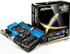
ASRock Z97 Extreme6 Quick Installation Guide
ASRock Z97 Extreme6 Manual
 |
View all ASRock Z97 Extreme6 manuals
Add to My Manuals
Save this manual to your list of manuals |
ASRock Z97 Extreme6 manual content summary:
- ASRock Z97 Extreme6 | Quick Installation Guide - Page 1
and should not be constructed as a commitment by ASRock. ASRock assumes no responsibility for any errors or omissions that may appear in this documentation. With CALIFORNIA, USA ONLY The Lithium battery adopted on this motherboard contains Perchlorate, a toxic substance controlled in Perchlorate Best - ASRock Z97 Extreme6 | Quick Installation Guide - Page 2
The terms HDMI™ and HDMI High-Definition Multimedia Interface, and the HDMI logo are trademarks or registered trademarks of HDMI Licensing LLC in the United States and other countries. Manufactured under license under U.S. Patent Nos: 5,956,674; 5,974,380; 6,487,535; 7,003,467 & other U.S. and - ASRock Z97 Extreme6 | Quick Installation Guide - Page 3
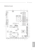
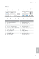
Keyboard /Mouse USB 3.0 T: USB1 B: USB2 Motherboard Layout 1 ATX12V1 CLRC BTN1 Z97 Extreme6 23 45 6 CPU_FAN2 CPU_FAN1 PWR_FAN1 DVI1 eSATA1 DDR3_A1 CHA_FAN3 TPMS1 1 CMOS Battery 1 CLRMOS1 8 USB3_4_5 1 Top: Center: FRONT Bottom: MIC IN 34 PCIE1 9 LAN Z97 Extreme6 33 LAN PCIE2 - ASRock Z97 Extreme6 | Quick Installation Guide - Page 4
Clear CMOS Jumper (CLRCMOS1) 10 SATA3 Connectors (SATA3_A3_A4) 11 SATA3 Connectors (SATA3_A1_A2) 12 SATA3 Connectors (SATA3_0_3) 13 SATA3 Connectors (SATA3_1_4) 14 SATA3 Connectors (SATA3_2_5) 15 SATA ) 30 PCIe Power Connector (PCIE_PWR1) 31 COM Port Header (COM1) 32 Front Panel Audio Header ( - ASRock Z97 Extreme6 | Quick Installation Guide - Page 5
ASM1042AE) 4 LAN RJ-45 Port (Intel® I218V)* 13 USB 3.0 Ports (USB3_34) 5 LAN RJ-45 Port (Realtek RTL8111GR)* (Intel® Z97) (USB3 Hub) 6 Central / Bass (Orange) 14 HDMI Port 7 Rear Speaker (Black) 15 eSATA Connector*** 8 Line In (Light Blue) 16 Clear CMOS Switch 9 Front Speaker (Lime - ASRock Z97 Extreme6 | Quick Installation Guide - Page 6
Please refer to the table below for the LAN port LED indications. ACT/LINK LED SPEED LED LAN Port Activity / Link LED Status Description Off Blinking to use the front panel audio. *** The eSATA connector supports SATA with cables within 1 meters. The SATA3_A4 connector is shared with the eSATA - ASRock Z97 Extreme6 | Quick Installation Guide - Page 7
the model you are using. You may find the latest VGA cards and CPU support list on ASRock's website as well. ASRock website http://www.asrock.com. 1.1 Package Contents • ASRock Z97 Extreme6 Motherboard (ATX Form Factor) • ASRock Z97 Extreme6 Quick Installation Guide • ASRock Z97 Extreme6 Support CD - ASRock Z97 Extreme6 | Quick Installation Guide - Page 8
Processors (Socket 1150) • Digi Power design • 12 Power Phase design • Supports Intel® Turbo Boost 2.0 Technology • Supports Intel® K-Series unlocked CPUs • Supports ASRock BCLK Full-range Overclocking • Intel® Z97 Memory • Dual Channel DDR3 Memory Technology • 4 x DDR3 DIMM Slots • Supports DDR3 - ASRock Z97 Extreme6 | Quick Installation Guide - Page 9
Z97 Extreme6 Expansion Slot Graphics • 2 x PCI Express 3.0 x16 Clear Video HD Technology, Intel® InsiderTM, Intel® HD Graphics 4400/4600 • Pixel Shader 5.0, DirectX 11.1 • Max. shared memory 1792MB • Three graphics output options: DVI-I, HDMI and DisplayPort 1.2 • Supports Triple Monitor • Supports - ASRock Z97 Extreme6 | Quick Installation Guide - Page 10
Audio • 7.1 CH HD Audio with Content Protection (Realtek ALC1150 Audio Codec) • Premium Blu-ray Audio support • Supports Surge Protection (ASRock Full Spike Protection) • Supports Purity Sound™ 2 - Nichicon Fine Gold Series Audio Caps - 115dB SNR DAC with Differential Amplifier - TI® NE5532 Premium - ASRock Z97 Extreme6 | Quick Installation Guide - Page 11
Z97 Extreme6 Storage Connector • 4 x USB 3.0 Ports (Intel® Z97) (Supports ESD Protection (ASRock Full Spike Protection)) • 2 x RJ-45 LAN Ports with LED (ACT/LINK LED and SPEED LED) • 1 x Clear CMOS Switch • HD Audio Jacks: Rear Speaker / Central / Bass / Line in / Front Speaker / Microphone • 6 x - ASRock Z97 Extreme6 | Quick Installation Guide - Page 12
x 64Mb AMI UEFI Legal BIOS with multilingual GUI support (1 x Main BIOS and 1 x Backup BIOS) • Supports Secure Backup UEFI Technology • ACPI 1.1 Compliant wake up events • SMBIOS 2.3.1 Support • CPU, DRAM, PCH 1.05V, PCH 1.5V Voltage Multi-adjust- ment • Drivers, Utilities, AntiVirus Software (Trial - ASRock Z97 Extreme6 | Quick Installation Guide - Page 13
Z97 Extreme6 * For detailed product information, please visit our website: http://www.asrock.com Please realize that there is a certain risk involved with overclocking, including adjusting the setting in the BIOS, applying Untied Overclocking Technology, or using third-party overclocking tools. - ASRock Z97 Extreme6 | Quick Installation Guide - Page 14
the CPU. Unlike Gen1 M.2, Gen3 x4 M.2 works up to 6X faster! It also supports all lengths of M.2 devices (30mm, 42mm, 60mm, 80mm, and 110mm). Feel free to install your M.2 devices without any trouble. ASRock HDD Saver Technology A power supply connector placed near the SATA ports. It supports up - ASRock Z97 Extreme6 | Quick Installation Guide - Page 15
Z97 Extreme6 ASRock A-Tuning A-Tuning is ASRock's multi purpose software suite with a new interface, more new features and improved utilities. ASRock Disk Health Report Displaying detailed HDD information. You can check the model names, capacities, temperatures, SMART info, health status, and other - ASRock Z97 Extreme6 | Quick Installation Guide - Page 16
pages? Just select "UEFI Guide"! The tutorial will explain every detailed setting and help you to customize your UEFI easily. ASRock Instant Flash ASRock Instant Flash is a BIOS flash utility embedded in Flash ROM. This convenient BIOS update tool allows you to update the system BIOS in a few clicks - ASRock Z97 Extreme6 | Quick Installation Guide - Page 17
. ASRock Easy RAID Installer ASRock Easy RAID Installer can help you to copy the RAID driver from the support CD to your USB storage device. After copying the RAID driver to your USB storage device, please change "SATA Mode" to "RAID", then you can start installing the OS in RAID mode. ASRock Easy - ASRock Z97 Extreme6 | Quick Installation Guide - Page 18
to ensure that the motherboard fits into it. Pre-installation Precautions Take note of the following precautions before you install motherboard components or change any motherboard settings. • Make sure to unplug the power cord before installing or removing the motherboard components. Failure to do - ASRock Z97 Extreme6 | Quick Installation Guide - Page 19
Z97 Extreme6 2.1 Installing the CPU 1. Before you insert the 1150-Pin CPU into the socket, please check if the PnP cap is on the socket, if the CPU surface is unclean, or if there are any bent pins in the socket. Do not force to insert the CPU into the socket if above situation is found. Otherwise, - ASRock Z97 Extreme6 | Quick Installation Guide - Page 20
4 5 18 3 English - ASRock Z97 Extreme6 | Quick Installation Guide - Page 21
Z97 Extreme6 Please save and replace the cover if the processor is removed. The cover must be placed if you wish to return the motherboard for after service. 19 English - ASRock Z97 Extreme6 | Quick Installation Guide - Page 22
2.2 Installing the CPU Fan and Heatsink 1 2 CPU_FAN English 20 - ASRock Z97 Extreme6 | Quick Installation Guide - Page 23
Z97 Extreme6 2.3 Installing Memory Modules (DIMM) This motherboard provides four 240-pin DDR3 (Double Data Rate 3) DIMM slots, and supports Dual Channel Memory Technology. 1. For dual channel configuration, you always need to install identical (the same brand, speed, size and chip-type) DDR3 DIMM - ASRock Z97 Extreme6 | Quick Installation Guide - Page 24
1 2 3 22 English - ASRock Z97 Extreme6 | Quick Installation Guide - Page 25
Z97 Extreme6 2.4 Expansion Slots (PCI Express Slots) There are 5 PCI Express slots and 1 mini-PCI Express slot on the motherboard. Before installing an expansion card, please make sure that the power supply is switched off or the power cord is unplugged. Please read the documentation of the - ASRock Z97 Extreme6 | Quick Installation Guide - Page 26
CLRCMOS1 for 5 seconds. However, please do not clear the CMOS right after you update the BIOS. If you need to clear the CMOS when you just finish updating the BIOS, you must boot up the system first, and then shut it down before you do the clear-CMOS action. Please be noted that the password, date - ASRock Z97 Extreme6 | Quick Installation Guide - Page 27
Z97 Extreme6 2.6 Onboard Headers and Connectors Onboard headers and connectors are NOT jumpers. Do NOT place jumper caps over these headers and connectors. Placing jumper caps over the headers and connectors will cause permanent damage to the motherboard. System Panel Header (9-pin PANEL1) (see - ASRock Z97 Extreme6 | Quick Installation Guide - Page 28
® Z97 SATA ports (SATA3_0) for your bootable devices. Serial ATA Express Connector (SATAE_1: see p.1, No. 15) 26 Please connect either SATA or PCIe storage devices to this connector. The SATA Express connector is shared with the SATA3_4, SATA3_5 and the M.2_SSD (NGFF) Socket 3 (M2_2). *The SATA - ASRock Z97 Extreme6 | Quick Installation Guide - Page 29
Z97 Extreme6 USB 2.0 Headers (9-pin USB2_3) (see p.1, No. 25) (9-pin USB4_5) (see p.1, No. 26) (USB1) (see p.1, No. 24) USB_PWR PP+ GND DUMMY 1 GND P+ PUSB_PWR There are two headers and one port on this motherboard. Each USB 2.0 header can support two ports. USB 3.0 Headers (19-pin USB3_4_5) ( - ASRock Z97 Extreme6 | Quick Installation Guide - Page 30
support HDA to function correctly. Please follow the instructions in our manual and chassis manual to install your system. 2. If you use an AC'97 audio panel, please install 4 This motherboard pro- 3 2 vides a 4-Pin CPU fan 1 (Quiet Fan) connector. If you plan to connect a 3-Pin CPU fan, please - ASRock Z97 Extreme6 | Quick Installation Guide - Page 31
Z97 Extreme6 ATX Power . 28) Serial Port Header (9-pin COM1) (see p.1, No. 31) 12 24 1 13 8 5 4 1 GND +12V DETECT 1 This motherboard provides a 24- cable to this connector when more than three graphics cards are installed. Please connect the HDD Saver Cable to this connector to manage - ASRock Z97 Extreme6 | Quick Installation Guide - Page 32
TPM Header 1 (17-pin TPMS1) (see p.1, No. 33) This connector supports Trusted Platform Module (TPM) system, which can securely store keys, digital certificates, passwords, and data. A TPM system also helps enhance network security, protects digital identities, - ASRock Z97 Extreme6 | Quick Installation Guide - Page 33
Z97 Extreme6 2.7 Smart Switches The motherboard has four smart switches: Power Switch, Reset Switch, Clear CMOS Switch and one BIOS Selection Switch, allowing users to quickly turn on/off the system, reset the system, clear the CMOS values or boot from different BIOS. Power Switch (PWRBTN) (see - ASRock Z97 Extreme6 | Quick Installation Guide - Page 34
makes troubleshooting even easier. Please see the diagrams below for reading the Dr. Debug codes. Code Description 00 Please check if the CPU is installed correctly and then clear CMOS. 0d Problem related to memory, VGA card or other devices. Please clear CMOS, re-install the memory and - ASRock Z97 Extreme6 | Quick Installation Guide - Page 35
Z97 Extreme6 b4 Problem related to USB devices. Please try removing all USB devices. b7 Problem related to memory. Please re-install the CPU and memory then clear CMOS. If the problem still exists, please install only one memory module or try using other memory modules. d6 The VGA could - ASRock Z97 Extreme6 | Quick Installation Guide - Page 36
; you can only choose either the M.2_SSD (NGFF) Socket 3 (M2_2) or the SATA Express connector to use. *The M.2_SSD (NGFF) Socket 3 supports SSD drives. Please note that the WiFi or other non-SSD M.2 modules are not supported. Installing the M.2_SSD (NGFF) Module Step 1 Prepare a M.2_SSD (NGFF - ASRock Z97 Extreme6 | Quick Installation Guide - Page 37
E D C B A C B A E D C B A Z97 Extreme6 Step 3 Move the standoff based on the module type and length. film on the nut to be used. Hand tighten the standoff into the desired nut location on the motherboard. Step 5 Align and gently insert the M.2 (NGFF) SSD module into the M.2 slot. Please - ASRock Z97 Extreme6 | Quick Installation Guide - Page 38
this might damage the module. M.2_SSD (NGFF) Module Support List PCIe Interface SATA Interface Plextor PX-AG256M6e Plextor PX-AG512M6e SanDisk SD6PP4M-128G SanDisk the latest updates of M.2_SSD (NFGG) module support list, please visit our website for details: http://www.asrock.com English 36 - ASRock Z97 Extreme6 | Quick Installation Guide - Page 39
Z97 Extreme6 2.10 HDD Saver Cable Installation Guide The HDD Saver Connector on this motherboard allows you to switch on and off the connected HDDs via software when needed. This design secures more privacy, saves more energy, and extends the HDDs' lifespans. Please follow the steps below to install - ASRock Z97 Extreme6 | Quick Installation Guide - Page 40
tzter VGA-Karten und Prozessoren auf der ASRock-Webseite: ASRock-Website http://www.asrock.com. 1.1 Lieferumfang • ASRock Z97 Extreme6 - Motherboard (ATX-Formfaktor) • ASRock Z97 Extreme6 - Schnellinstallationsanleitung • ASRock Z97 Extreme6 - Support-CD • 4 x Serial-ATA- (SATA) Datenkabel (optional - ASRock Z97 Extreme6 | Quick Installation Guide - Page 41
Z97 Extreme6 1.2 Technische Daten Plattform • ATX-Formfaktor • Leiterplatte mit hochdichtem Glasgewebe Einzigartige Merkmale ASRock-Superlegierung • XXL-Kühlkörper mit Aluminiumlegierung • Erstklassige Legierungsdrossel (reduziert Kernverlust im Vergleich zu Eisenpulverdrossel um 70 %) • Dual- - ASRock Z97 Extreme6 | Quick Installation Guide - Page 42
AVC, MVC (S3D) und MPEG-2 Full HW Encode1, Intel® InTruTM 3D, Intel® Clear Video HD Technology, Intel® InsiderTM, Intel® HD Graphics 4400/4600 • Pixel Shader 5.0, ) • Unterstützt HDCP mit DVI-I-, HDMI- und DisplayPort 1.2-Ports • Unterstützt Blu-ray- (BD) Wiedergabe (Full HD/1080p) mit DVI - ASRock Z97 Extreme6 | Quick Installation Guide - Page 43
Z97 Extreme6 Audio LAN Rückblende, E/A • 7.1-Kanal-HD-Audio mit Inhaltsschutz (Realtek ALC1150Audiocodec) • Erstklassige Blu-ray-Audiounterstützung • Unterstützt Überspannungsschutz (ASRock Full Spike Protection) • Unterstützt Purity Sound™ 2 - Nichicon-Audiokappen der Fine Gold-Serie - 115-dB-SRV - ASRock Z97 Extreme6 | Quick Installation Guide - Page 44
-LAN-Port mit LED (Aktivität/Verbindung-LED und Geschwindigkeit-LED) • 1 x CMOS-löschen-Schalter • HD-Audioanschlüsse: Hintere Lautsprecher / Zentral / Bass / Line-in / Vorderer Lautsprecher / Mikrofon • 6 x SATA-III-6,0-Gb/s-Anschlüsse per Intel® Z97, unterstützt RAID (RAID 0, RAID 1, RAID 5, RAID - ASRock Z97 Extreme6 | Quick Installation Guide - Page 45
Z97 Extreme6 • 1 x Audioanschluss an Frontblende • 1 x Thunderbolt-Erweiterungskartenanschluss • 2 x USB 2.0-Stiftleisten (unterstützen 4 USB 2.0-Ports) (un- terstützt Schutz gegen elektrostatische Entladung (ASRock Full Spike Protection)) • 1 x Vertikal, Typ A, USB 2.0 • 2 x USB 3.0-Stiftleisten ( - ASRock Z97 Extreme6 | Quick Installation Guide - Page 46
asrock.com Bitte beachten Sie, dass mit einer Übertaktung, zu der die Anpassung von BIOS-Einstellungen, die Anwendung der Untied Overclocking ®-Betriebssysteme mit 64 Bit haben keine derartigen Beschränkungen. Mit ASRock XFast RAM können Sie den Speicher einsetzen, den Windows® nicht nutzen kann. - ASRock Z97 Extreme6 | Quick Installation Guide - Page 47
Z97 Extreme6 1.3 Jumpereinstellung Die Abbildung zeigt, wie die Jumper eingestellt werden mit einer Jumper-Kappe kurz. Löschen Sie den CMOS jedoch nicht direkt nach der BIOS-Aktualisierung. Falls Sie den CMOS direkt nach Abschluss der BIOS-Aktualisierung löschen müssen, starten Sie das System zun - ASRock Z97 Extreme6 | Quick Installation Guide - Page 48
an diesen Stiftleisten und Anschlüssen an. Durch Anbringen von Jumper-Kappen an diesen Stiftleisten und Anschlüssen können Sie das Motherboard dauerhaft beschädigen. Systemblende-Stiftleiste (9-polig, PANEL1) (siehe S. 1, Nr. 23) PLED+ PLEDPWRBTN# GND 1 GND RESET# GND HDLEDHDLED+ Verbinden Sie - ASRock Z97 Extreme6 | Quick Installation Guide - Page 49
SATA3_2_5 SATA3_1_4 SATA3_0_3 SATA3_A1_A2 SATA3_A3_A4 Deutsch Z97 Extreme6 Betrieb-LED-Stiftleiste (3-polig, SATA-Express-Anschluss geteilt. Nutzen Sie zum Minimieren der Startzeit Intel® Z97-SATA-Ports einen Port an diesem Motherboard. Jede USB 2.0-Stiftleiste kann zwei Ports unterstützen. 47 - ASRock Z97 Extreme6 | Quick Installation Guide - Page 50
3.0-Ports an der E/ A-Blende befinden sich zwei Stiftleisten an diesem Motherboard. Jede USB 3.0-Stiftleiste kann zwei Ports OUT_RET sind nur für das HD-Audiopanel vorgesehen. Sie müssen sie nicht für das AC'97-Audiopanel verbinden. E. Rufen Sie zum Aktivieren des vorderen Mikrofons das „FrontMic ( - ASRock Z97 Extreme6 | Quick Installation Guide - Page 51
Z97 Extreme6 Gehäuselautsprecherstiftleiste (4-polig, SPEAKER1) (siehe S. 1, Nr. 17) DUMMY SPEAKER GN D FAN_SPEED FAN_VOLTAGE GND 4 Dieses Motherboard bietet 3 einen 4-poligen CPU- 2 1 Lüfteranschluss (lautloser Lüfter). Falls Sie einen 3-poligen CPU-Lüfter anschließen möchten, verbinden - ASRock Z97 Extreme6 | Quick Installation Guide - Page 52
. 22) ThunderboltErweiterungskartenanschluss (5-polig, TB1) (siehe S. 1, Nr. 28) Serieller-Port-Stiftleiste (9-polig, COM1) (siehe S. 1, Nr. 31) TPM-Stiftleiste (17-polig, TPMS1) (siehe S. 1, Nr. 33) 50 8 5 Dieses Motherboard bietet einen 8-poligen ATX-12-V-Netzanschluss. 4 1 Bitte schließen - ASRock Z97 Extreme6 | Quick Installation Guide - Page 53
Z97 Extreme6 1.5 Intelligente Schalter Das Motherboard hat vier intelligente Schalter: Ein-/Ausschalter, Reset-Schalter, CMOS-löschen-Schalter und ein BIOS-Auswahlschalter, wodurch Benutzer das System schnell ein-/abschalten, zurücksetzen, die CMOS-Werte löschen oder von einem anderen BIOS starten - ASRock Z97 Extreme6 | Quick Installation Guide - Page 54
sur le site Internet de ASRock. Site Internet ASRock http://www.asrock.com. 1.1 Contenu de l'emballage • Carte mère ASRock Z97 Extreme6 (facteur de forme ATX) • Guide d'installation rapide ASRock Z97 Extreme6 • CD d'assistance ASRock Z97 Extreme6 • 4 x câbles de données Serial ATA (SATA) (Optionnel - ASRock Z97 Extreme6 | Quick Installation Guide - Page 55
ration Intel® CoreTM (socket 1150) • Conception Digi Power • Alimentation à 12 phases • Prend en charge la technologie Intel® Turbo Boost 2.0 • Prend en charge les processeurs débloqués de la série K Intel® • Prend en charge l'overclocking ASRock BCLK Full-range • Intel® Z97 Mémoire • Technologie - ASRock Z97 Extreme6 | Quick Installation Guide - Page 56
MVC (S3D) et MPEG-2 Full HW Encode1, Intel® InTruTM 3D, Intel® Clear Video HD Technology, Intel® InsiderTM, Intel® HD Graphics 4400/4600 • Pixel et HBR (High Bit Rate Audio) avec port HDMI (un écran compatible HDMI est requis) • Prend en charge HDCP via ports DVI-I, HDMI et DisplayPort 1.2 • Prend - ASRock Z97 Extreme6 | Quick Installation Guide - Page 57
Z97 Extreme6 Audio Réseau Connectique du panneau arrière • Audio 7.1 CH HD avec protection du contenu (codec audio Realtek ALC1150) • Compatible audio Blu-ray Premium • Protection contre les surtensions (Protection complète contre les pics ASRock) • Prend en charge Purity Sound™ 2 - Couvercles - ASRock Z97 Extreme6 | Quick Installation Guide - Page 58
ASRock)) • 2 x port RJ-45 LAN avec LED (LED ACT/LIEN et LED VITESSE) • 1 x bouton Clear CMOS • Connecteurs jack audio HD : Haut-parleur arrière / central / basses / entrée ligne / haut-parleur avant / microphone • 6 x connecteurs SATA3 6,0 Gb/s par Intel® Z97, compatibles RAID (RAID 0, RAID 1, RAID - ASRock Z97 Extreme6 | Quick Installation Guide - Page 59
Z97 Extreme6 Caractéristiques du BIOS CD inclus • 1 x connecteur audio panneau frontal • 1 x connecteur Thunderbolt AIC • 2 x embases USB 2.0 (4 ports USB 2.0 pris en charge) (Pro- tection contre les décharges électrostatiques (Protection complète contre les pics ASRock)) • 1 x port V, CPU Vcore, - ASRock Z97 Extreme6 | Quick Installation Guide - Page 60
asrock.com Il est important de signaler que l'overcloking présente certains risques, incluant des modifications du BIOS, l'application d'une technologie d'overclocking déliée et l'utilisation d'outils d'overclocking utiliser ASRock XFast RAM pour utiliser la mémoire dont Windows® ne peut se servir. - ASRock Z97 Extreme6 | Quick Installation Guide - Page 61
Z97 Extreme6 1.3 Configuration des cavaliers (jumpers) L'illustration ci-dessous vous renseigne sur la configuration des cavaliers (jumpers). Lorsque le capuchon du cavalier est installé sur les broches, le cavalier est « courtcircuité ». Si le capuchon du cavalier n'est pas installé sur les broches - ASRock Z97 Extreme6 | Quick Installation Guide - Page 62
1.4 Embases et connecteurs de la carte mère Les embases et connecteurs situés sur la carte NE SONT PAS des cavaliers. Ne placez JAMAIS de capuchons de cavaliers sur ces embases ou connecteurs. Placer un capuchon de cavalier sur ces embases ou connecteurs endommagera irrémédiablement votre carte mère - ASRock Z97 Extreme6 | Quick Installation Guide - Page 63
Z97 Extreme6 SATA Express. Pour minimiser le temps au démarrage, utilisez les ports Intel® Z97 SATA SATA ou PCIe à ce connecteur. Le connecteur SATA Express est partagé avec SATA3_4, SATA3_5 et M.2_SSD (NGFF) socket 3 (M2_2). USB_PWR PP+ GND DUMMY 1 GND P+ PUSB_PWR Il y a deux embases et un port - ASRock Z97 Extreme6 | Quick Installation Guide - Page 64
Chaque embase USB 3.0 peut prendre en charge deux ports. IntA_P_D+ IntA_P_DGND IntA_P_SSTX+ IntA_P_SSTXGND IntA_P_SSRX+ IntA_P_SSRXVbus 1 suivre les instructions figurant dans notre manuel et dans le manuel du châssis pour installer votre système. 2. Si vous utilisez un panneau audio AC'97, - ASRock Z97 Extreme6 | Quick Installation Guide - Page 65
Z97 Extreme6 Embase du haut-parleur du châssis (SPEAKER1 à 4 broches) (voir p.1, No. 17) DUMMY SPEAKER 1 +5V DUMMY Veuillez brancher le hautparleur du châssis sur cette - ASRock Z97 Extreme6 | Quick Installation Guide - Page 66
4 broches à ce connecteur lorsque plus de trois cartes graphiques sont installées. Veuillez connecter le câble de 1 sauvegarde HDD à ce Français Connecteur Thunderbolt AIC (TB1 à 5 broches) (voir p.1, No. 28) Embase pour port série (COM1 à 9 broches) (voir p.1, No. 31) Embase TPM (TPMS1 à 17 - ASRock Z97 Extreme6 | Quick Installation Guide - Page 67
Z97 Extreme6 1.5 Boutons intelligents La carte mère est équipée de quatre boutons intelligents : bouton de mise en marche, bouton de réinitialisation, bouton d'effacement CMOS et bouton de sélecteur de BIOS qui permettent aux utilisateurs d'allumer/éteindre le système, de réinitialiser le système, - ASRock Z97 Extreme6 | Quick Installation Guide - Page 68
supporto di CPU anche sul sito Web di ASRock. Sito Web di ASRock http://www.asrock.com. 1.1 Contenuto della confezione • Scheda madre ASRock Z97 Extreme6 (Form Factor ATX) • Guida all'installazione rapida di ASRock Z97 Extreme6 • CD di supporto di ASRock Z97 Extreme6 • 4 x cavi dati Serial ATA (SATA - ASRock Z97 Extreme6 | Quick Installation Guide - Page 69
4th Gen e 5th Generation Intel® CoreTM (Socket 1150) • Design Digi Power • Potenza a 12 fasi • Supporta la tecnologia Intel® Turbo Boost 2.0 • Supporto di CPU unlocked Intel® K-Series • Supporta gamma completa overclocking BCLK ASRock • Intel® Z97 Memoria • Tecnologia con memoria DDR3 a doppio - ASRock Z97 Extreme6 | Quick Installation Guide - Page 70
della scheda video HD Intel® e le uscite VGA possono essere supportate soltanto con processori con GPU integrata. • Supporta la videografica integrata (S3D) e MPEG-2 Full HW Encode1, Intel® InTruTM 3D, tecnologia Intel® Clear Video HD, Intel® InsiderTM, Intel® HD Graphics 4400/4600 • Pixel Shader - ASRock Z97 Extreme6 | Quick Installation Guide - Page 71
Z97 Extreme6 Audio LAN I/O pannello posteriore • Audio HD a 7.1 canali con Content Protection (codec audio Realtek ALC1150) • Supporto audio Blu-ray Premium • Supporto protezione da sovratensione (protezione completa ASRock dai picchi di corrente) • Supporto di Purity Sound™ 2 - Cappucci audio - ASRock Z97 Extreme6 | Quick Installation Guide - Page 72
• 4 x Porte USB 3.0 (Intel® Z97) (supporto protezione da scariche elettrostatiche (ESD) (protezione completa ASRock dai picchi di corrente)) • 2 Porta RJ-45 LAN con LED (LED ACT/LINK e LED SPEED) • 1 x interruttore per azzerare la CMOS • Connettori audio HD: altoparlante posteriore/centrale/ basso/ - ASRock Z97 Extreme6 | Quick Installation Guide - Page 73
Z97 Extreme6 Funzione BIOS • 1 connettore audio pannello frontale • 1 x Connettore Thunderbolt AIC • 2 x Collettori USB 2.0 (supporto di 4 porte USB 2.0) (suppor- to protezione da scariche elettrostatiche (ESD) (protezione completa ASRock dai picchi di corrente)) • 1 x USB 2.0 verticale tipo A • 2 - ASRock Z97 Extreme6 | Quick Installation Guide - Page 74
: http://www.asrock.com Prestare attenzione al potenziale rischio previsto nella pratica di overclocking, inclusa la regolazione delle impostazioni nel BIOS, l'applicazione di tecnologia di Untied Overclocking o l'utilizzo di strumenti di overclocking di terze parti. L'overclocking può influenzare - ASRock Z97 Extreme6 | Quick Installation Guide - Page 75
Z97 Extreme6 1.3 Impostazione jumper L'illustrazione mostra in che modo vengono impostati i jumper. Quando il per 5 secondi. Tuttavia, non azzerare la CMOS subito dopo aver aggiornato il BIOS. Se è necessario azzerare la CMOS dopo l'aggiornamento del BIOS, è necessario riavviare prima il sistema e in - ASRock Z97 Extreme6 | Quick Installation Guide - Page 76
1.4 Header e connettori sulla scheda Gli header e i connettori sulla scheda NON sono jumper. NON posizionare cappucci del jumper su questi header e connettori. Il posizionamento di cappucci del jumper su header e connettori provocherà danni permanenti alla scheda madre. Header sul pannello del - ASRock Z97 Extreme6 | Quick Installation Guide - Page 77
Italiano Z97 Extreme6 Header LED porte SATA Intel ® Z97 (SATA3_0) per i dispositivi di'avvio. Connettore Serial ATA Express (SATAE_1: vedere pag.1, n. 15) Collegare i dispositivi d'archiviazione SATA o PCIe a questo connettore. Il connettore SATA Express è condiviso con SATA3_4, SATA3_5 e Socket - ASRock Z97 Extreme6 | Quick Installation Guide - Page 78
due collettori. Ciascun header USB 3.0 può supportare due porte. IntA_P_D+ IntA_P_DGND IntA_P_SSTX+ IntA_P_SSTXGND IntA_P_SSRX+ IntA_P_SSRXVbus 1 istruzioni presenti nel nostro manuale e nel manuale dello chassis per installare il sistema. 2. Se si utilizza un pannello audio AC'97, installarlo sull - ASRock Z97 Extreme6 | Quick Installation Guide - Page 79
Z97 Extreme6 Header altoparlante chassis (SPEAKER1 a 4 pin) (vedere pag. 1, n. 17) DUMMY SPEAKER 1 + pin) (vedere pag. 1, n. 6) GND FAN_VOLTAGE CHA_FAN_SPEED GND FAN_VOLTAGE CHA_FAN_SPEED Connettori della ventola della CPU (CPU_FAN1 a 4 pin) (vedere pag. 1, n. 2) (CPU_FAN2 a 3 pin) (vedere pag - ASRock Z97 Extreme6 | Quick Installation Guide - Page 80
utilizzare un'alimentazione ATX a 4 pin, collegarla lungo il pin1 e il pin 5. Collegare un cavo di alimentazione molex a 4 pin a questo connettore quando sono installate più di tre schede grafiche. Collegare il cavo HDD Saver a questo connettore per gestire lo stato d'alimentazione dell'unità HDD - ASRock Z97 Extreme6 | Quick Installation Guide - Page 81
Z97 Extreme6 1.5 Interruttori intuitivi La scheda madre è dotata di quattro interruttori intuitivi: Interruttore d'alimentazione, interruttore di ripristino, interruttore Clear CMOS ed un interruttore di selezione BIOS che consentono di accendere/spegnere rapidamente il sistema, ripristinare il - ASRock Z97 Extreme6 | Quick Installation Guide - Page 82
de la CPU, en el sitio web de ASRock. Sitio web de ASRock http://www. asrock.com. 1.1 Contenido del paquete • Placa base ASRock Z97 Extreme6 (Factor de forma ATX) • Guía de instalación rápida de ASRock Z97 Extreme6 • CD de soporte de ASRock Z97 Extreme6 • 4 cables de datos Serie ATA (SATA) (Opcional - ASRock Z97 Extreme6 | Quick Installation Guide - Page 83
Intel® CoreTM (Socket 1150) • Diseño Digi Power • Diseño de 12 fases de alimentación • Compatible con la tecnología de Intel® Turbo Boost 2.0 • Compatible con CPU serie K desbloqueada de Intel® • Compatible con overclocking de rango completo BCLK de ASRock • Intel® Z97 Memoria • Tecnolog - ASRock Z97 Extreme6 | Quick Installation Guide - Page 84
integrada de gráficos HD de Intel®: Intel® Quick Sync Video con AVC, MVC (S3D) y MPEG-2 Full HW Encode1, Intel® InTruTM 3D, Intel® Clear Video HD Technology, Intel® InsiderTM, Intel® HD Graphics 4400/4600 • Pixel Shader 5.0, DirectX 11.1 • Memoria compartida máxima: 1792MB • Tres opciones de salida - ASRock Z97 Extreme6 | Quick Installation Guide - Page 85
Z97 Extreme6 Audio • 7.1 Audio CH HD con Protección de contenido (Realtek ALC1150 Audio Codec) • Compatible con audio Blu-ray Premium • Compatible con protección por sobretensión (protección ASRock Full Spike) • Compatible con Purity Sound™ 2 - Tapas de audio Nichion de la serie Fine Gold - 115dB - ASRock Z97 Extreme6 | Quick Installation Guide - Page 86
Conectores • 6 conectores SATA3 de 6,0 Gb/s de Intel® Z97, compatibilidad con RAID (RAID 0, RAID 1, RAID 5, RAID 10, Intel Rapid Storage Technology 13 e Intel Smart Response Technology), NCQ, AHCI y conexión en caliente y tecnología de ahorro ASRock HDD • 4 conectores SATA3 de 6,0 Gb/s de ASMedia - ASRock Z97 Extreme6 | Quick Installation Guide - Page 87
Z97 Extreme6 Función del BIOS CD de soporte Monitor del hardware • 1 Conector de audio del panel frontal • 1 conector Thunderbolt AIC • 2 cabezales USB 2.0 (compatible con 4 puertos USB 2.0) (compatible con protección contra electricidad estática (protección ASRock Full Spike)) • 1 USB 2.0 - ASRock Z97 Extreme6 | Quick Installation Guide - Page 88
ón acerca del producto, visite nuestro sitio web: http://www.asrock.com Tenga en cuenta que existen ciertos riesgos relacionados con el overclocking (sobreaceleración), incluyendo el ajuste de la configuración del BIOS, aplicando la Tecnología overcloking no vinculada o utilizando las herramientas - ASRock Z97 Extreme6 | Quick Installation Guide - Page 89
Z97 Extreme6 1.3 Instalación de los puentes La instalación muestra cómo deben instalarse durante 5 segundos. Sin embargo, no borre el CMOS justo después de que haya actualizado el BIOS. Si necesita borrar el CMOS cuando acabe de actualizar el BIOS, deberá arrancar el sistema primero y, a continuaci - ASRock Z97 Extreme6 | Quick Installation Guide - Page 90
1.4 Conectores y cabezales incorporados Los cabezales y conectores incorporados NO son puentes. NO coloque tapas de puente sobre estos cabezales y conectores. Si coloca tapas de puente sobre los cabezales y conectores dañará de forma permanente la placa base. Cabezal del panel del sistema (PANEL1 - ASRock Z97 Extreme6 | Quick Installation Guide - Page 91
SATA3_2_5 SATA3_1_4 SATA3_0_3 SATA3_A1_A2 SATA3_A3_A4 Español Z97 Extreme6 Cabezal de indicador LED de alimentación (PLED1 de 3 pines) o a este conector dispositivos de almacenamiento SATA o PCIe. El conector express SATA se comparte con SATA3_4, SATA3_5 y Socket 3 M.2_SSD (NGFF)) (M2_2). USB_PWR - ASRock Z97 Extreme6 | Quick Installation Guide - Page 92
á ser compatible con HDA para que pueda funcionar correctamente. Siga las instrucciones que se indican en nuestro manual y en el manual del chasis para instalar su sistema. 2. Si utiliza un panel de audio AC'97, colóquelo en el cabezal de audio del panel frontal siguiendo los pasos que se describen - ASRock Z97 Extreme6 | Quick Installation Guide - Page 93
Z97 Extreme6 Cabezal de altavoces del chasis (SPEAKER1 de 4 pines) (consulte la pág.1, N.º 17) haga coincidir el cable negro con el pin de conexión a tierra. Conectores del ventilador de la CPU (CPU_FAN1 de 4 pines) (consulte la pág.1, N.º 2) FAN_SPEED_CONTROL FAN_SPEED + 12V GN D (CPU_FAN2 - ASRock Z97 Extreme6 | Quick Installation Guide - Page 94
a este conector para gestionar el estado de la potencia de HDD. Conecte un cable de señal de 5 pines (cables GPIO) a este conector cuando instales una tarjeta adicional (AIC) Thunderbolt™. Este cabezal COM1 admite un módulo de puerto serie. Español Cabezal TPM 1 (TPMS1 de 17 pines) (consulte la - ASRock Z97 Extreme6 | Quick Installation Guide - Page 95
Z97 Extreme6 1.5 Interruptores inteligentes La placa base contiene cuatro interruptores inteligentes: Interruptor de alimentación, interruptor de reseteo, interruptor de borrado de CMOS y un interruptor de selección BIOS, que permiten a los usuarios encender y apagar rápidamente el sistema, - ASRock Z97 Extreme6 | Quick Installation Guide - Page 96
1 ASRock Z97 Extreme6 ASRock ASRock BIOS ASRock ASRock VGA ASRock http://www.asrock.com. 1.1 ASRock Z97 Extreme6 ATX ASRock Z97 Extreme6 ASRock Z97 Extreme6 • 4 Serial ATA (SATA 1 1 x карта ASRock SLI_Bridge_2S • 1 x HDD Saver • 2 x M.2 • 1 x mini-PCIe 94 - ASRock Z97 Extreme6 | Quick Installation Guide - Page 97
Z97 Extreme6 1.2 ATX ASRock Super Alloy XXL Alloy Choke 70 DSM) • NexFET™ MOSFET 12K Platinum Sapphire Black ASRock Ultra M.2 (PCIe Gen3 x4 ASRock HDD Saver ASRock Full Spike Protection ASRock Cloud ASRock APP Shop 4го и 5 Intel® CoreTM (Socket 1150) • Digi - ASRock Z97 Extreme6 | Quick Installation Guide - Page 98
-in Visuals и VGA Intel® HD Graphics: Intel® Quick Sync Video с AVC, MVC (S3D) и MPEG-2 Full HW Encode1, Intel® InTruTM 3D, Intel® Clear Video HD Technology, Intel® InsiderTM, Intel® HD Graphics 4400/4600 • Pixel Shader 5.0, DirectX 11.1 1792 DVI-I, HDMI и DisplayPort 1.2 HDMI 4K × 2K - ASRock Z97 Extreme6 | Quick Installation Guide - Page 99
Z97 Extreme6 Аудио ЛВС • 7.1 HD Audio Realtek ALC1150) Premium Blu-ray Audio ASRock Full Spike Intel® Remote Wake Intel® I218V Wake-On-WAN (с Realtek RTL- 8111GR Wake-On-LAN ASRock Full Spike Protection Realtek RTL8111GR Energy Efficient Ethernet 802.3az PXE • 1 x PS/2 1 - ASRock Z97 Extreme6 | Quick Installation Guide - Page 100
с Intel® Z97 RAID (RAID 0, RAID 1, RAID 5, RAID 10, Intel Rapid Storage Technology 13 и Intel Smart Response Technology), NCQ, AHCI ASRock HDD Saver • 4 x SATA3 6,0 ГБ/с с ASMedia ASM1061 NCQ, AHCI ASRock HDD Saver SATA3_A4 eSATA) • 1 x SATA Express SATA3_4, SATA3_5 и M.2_SSD (NGFF) Socket - ASRock Z97 Extreme6 | Quick Installation Guide - Page 101
Z97 Extreme6 • 1 x 1 x AIC Thunderbolt • 2 x USB 2.0 (до 4 USB 2.0 ASRock Full Spike Protection) • 1 USB 2.0 типа A • 2 x USB 3.0 (до 4 USB 3.0 ASRock Full Spike Protection) • 1 x Dr. Debug 1 x 1 x 1 x BIOS BIOS • 2 x 64 Мб AMI UEFI Legal BIOS 1 x BIOS и 1 x BIOS UEFI - ASRock Z97 Extreme6 | Quick Installation Guide - Page 102
http://www.asrock.com BIOS Untied Overclocking Technology 32 Windows 4 64 Windows Windows ASRock XFast RAM. 100 - ASRock Z97 Extreme6 | Quick Installation Guide - Page 103
Z97 Extreme6 1.3 3 1 и 2 CMOS (CLRCMOS1 1, № 9) CMOS CLRCMOS1 CMOS 15 2 и 3 на CLRCMOS1 на 5 CMOS BIOS CMOS BIOS CMOS CMOS. CMOS CMOS. 101 - ASRock Z97 Extreme6 | Quick Installation Guide - Page 104
1.4 9 PANEL1 1, № 23) PLED+ PLEDPWRBTN# GND 1 GND RESET# GND HDLEDHDLED+ PWRBTN RESET PLED S1/S3 S4 S5 HDLED 102 - ASRock Z97 Extreme6 | Quick Installation Guide - Page 105
Z97 Extreme6 3 PLED1 1, № 18) Serial ATA3 (SATA3_0_3 1, № 12) (SATA3_1_4 1, № 13) (SATA3_2_5 1, № 14) (SATA3_A1_A2 1, № 11) (SATA3_A3_A4 1, № 10) 1 PLED- PLED+ PLED+ SATA3 SATA 6,0 eSATA SATA3_A4 SATA3_4, SATA3_5 SATA Express Intel® Z97 SATA (SATA3_0 SATA - ASRock Z97 Extreme6 | Quick Installation Guide - Page 106
+ GND IntA_P_SSTXIntA_P_SSTX+ GND IntA_P_DIntA_P_D+ ID 9 HD_ AUDIO1 1, № 32) GND PRESENCE# MIC_RET OUT_RET 1 OUT2_L J_SENSE OUT2_R MIC2_R MIC2_L 104 1 HDA 2 AC'97 A Mic_IN (MIC) к MIC2_L. B Audio_R (RIN) к OUT2_R, Audio_L (LIN) к OUT2_L. C GND GND). D MIC_RET и OUT_RET - ASRock Z97 Extreme6 | Quick Installation Guide - Page 107
Z97 Extreme6 4 SPEAKER1 1, № 17) DUMMY SPEAKER 1 +5V DUMMY 4 CHA_ FAN1 1, № 16) (3 CHA_ FAN2 1, № 29) (3 CHA_ FAN3 1, № 34) (3 PWR_ FAN1 1, № 6) GND +12V CHA_FAN_SPEED FAN_SPEED_CONTROL GND FAN_VOLTAGE CHA_FAN_SPEED GND - ASRock Z97 Extreme6 | Quick Installation Guide - Page 108
12 В (8 ATX12V1 1, № 1) PCIe (4 PCIE_ PWR1 1, № 30) HDD Saver (4 SATA_ PWR_1 1, № 22) 8 5 4 1 GND +12V DETECT 1 8 12 4 ATX 1 5. 4 Molex. HDD Saver. Thunderbolt AIC (5 TB1 1, № 28) 9 COM1 1, № 31) RRXD1 DDTR#1 DDSR#1 CCTS#1 1 RRI#1 RRTS#1 GND TTXD1 DDCD#1 - ASRock Z97 Extreme6 | Quick Installation Guide - Page 109
Z97 Extreme6 1.5 BIOS BIOS. PWRBTN 1, № 20) Power RSTBTN 1, № 21) Reset CMOS (CLRCBTN 3, № 16) CMOS CMOS. BIOS (BIOS_SEL1 1, № 19) AB BIOS BIOS A или BIOS B. BIOS BIOS (BIOS_A) и BIOS BIOS_B BIOS BIOS BIOS BIOS UEFI Secure Backup UEFI BIOS - ASRock Z97 Extreme6 | Quick Installation Guide - Page 110
VGA e CPU mais recentes suportadas no site da ASRock. Site da ASRock http://www.asrock.com. 1.1 Conteúdo da embalagem • Placa Mãe ASRock Z97 Extreme6 (Fator de Forma ATX) • Guia de Instalação Rápida da ASRock Z97 Extreme6 • CD de Suporte da ASRock Z97 Extreme6 • 4 x Cabos de dados Serial ATA (SATA - ASRock Z97 Extreme6 | Quick Installation Guide - Page 111
Z97 Extreme6 Português 1.2 Especificações Plataforma • Formato ATX • Tecido de Vidro de Alta densidade PCB Característica Única CPU Chipset Super Liga ASRock Boost 2.0 • Suporta CPU desbloqueado da série K da Intel® • Suporta Overclocking total ASRock BCLK • Intel® Z97 Memória • Tecnologia - ASRock Z97 Extreme6 | Quick Installation Guide - Page 112
• Suporta gráficos incorporados Intel® HD: Intel® Quick Sync Video com AVC, MVC (S3D) e MPEG-2 Full HW Encode1, Intel® InTruTM 3D, Tecnologia Intel® Clear Video HD, Intel® InsiderTM, Gráficos Intel® HD 4400/4600 • Pixel Shader 5.0, DirectX 11.1 • Memória compartilhada máxima de 1792MB • Três opções - ASRock Z97 Extreme6 | Quick Installation Guide - Page 113
Z97 Extreme6 Áudio • Áudio HD de 7.1 canais com proteção de conteúdo (Codec de áudio Realtek ALC1150) • Suporte áudio Blu-ray superior • Suporta proteção contra sobretensão (Proteção Total Contra Picos ASRock) • Suporta Purity Sound™ 2 - Capacitor de Áudio Série Ouro Fino Nichicon - 115dB SNR DAC - ASRock Z97 Extreme6 | Quick Installation Guide - Page 114
Z97, suporte RAID (RAID 0, RAID 1, RAID 5, RAID 10, Tecnologia de Armazenamento Rápido Intel® 13 e Tecnologia de Resposta Inteligente Intel), NCQ, AHCI e Conexão a Quente e Tecnologia Protetora de HDD ASRock ASRock (O conector SATA3_A4 é compartilhada com a porta eSATA) • 1 x Conector SATA CPU - ASRock Z97 Extreme6 | Quick Installation Guide - Page 115
Z97 Extreme6 Português Funções da BIOS • 1 conector de áudio do painel frontal • 1 x Conector Thunderbolt AIC • 2 x Plataformas USB 2.0 (Suporta 4 portas USB 2.0) (Suporta Proteção ESD (Proteção Total Contra Picos ASRock)) • 1 USB 2.0 Tipo A Vertical • 2 x Plataformas USB 3.0 (Suporta 4 portas - ASRock Z97 Extreme6 | Quick Installation Guide - Page 116
nosso site: http://www.asrock.com Por favor, observe que existe um certo risco envolvendo overclocking, incluindo o ajuste das definições na BIOS, a aplicação de tecnologia Untied Overclocking ou a utilização de ferramentas de overclocking de terceiros. O overclocking poderá afetar a estabilidade do - ASRock Z97 Extreme6 | Quick Installation Guide - Page 117
Z97 Extreme6 1.3 Configuração dos jumpers A imagem abaixo mostra como os jumpers são configurados. segundos. No entanto, não apague o CMOS logo após ter realizado a atualização da BIOS. Se você precisar apagar o CMOS logo após ter terminado uma atualização da BIOS, deverá primeiro iniciar o sistema - ASRock Z97 Extreme6 | Quick Installation Guide - Page 118
1.4 Suportes e conectores onboard Os conectores e suportes onboard NÃO são jumpers. NÃO coloque tampas de jumpers sobre estes terminais e conectores Colocar tampas de jumpers sobre os terminais e conectores irá causar danos permanentes à placa-mãe. Suporte do painel de sistema (PAINEL1 de 9 pinos) - ASRock Z97 Extreme6 | Quick Installation Guide - Page 119
SATA3_2_5 SATA3_1_4 SATA3_0_3 SATA3_A1_A2 SATA3_A3_A4 Português Z97 Extreme6 Suporte LED de alimentação (PLED1 de 3 pinos) (ver p.1, N.º 18) Conectores ção do sistema. Estes dez conectores SATA3 suportam cabos de dados SATA para dispositivos de armazenamento interno com uma taxa de transferência - ASRock Z97 Extreme6 | Quick Installation Guide - Page 120
no chassi deverá suportar HDA para funcionar corretamente. Por favor, siga as instruções no nosso manual e no manual do chassi para instalar o seu sistema. 2. Se utilizar um painel de áudio AC'97, instale-o no terminal de áudio do painel frontal de acordo com os passos abaixo: A. Ligue Mic_IN (MIC - ASRock Z97 Extreme6 | Quick Installation Guide - Page 121
Z97 Extreme6 Suporte do alto-falante do chassi (SPEAKER1 de 4 pinos) (ver p.1, N.º 17) DUMMY placa mãe inclui um 3 2 conector de ventilador 1 da CPU (Ventilador silencioso) de 4 pinos. Se você pretende conectar um ventilador da CPU de 3 pinos, por favor, conecte-o ao Pino 1-3. Conector - ASRock Z97 Extreme6 | Quick Installation Guide - Page 122
Conector de alimentação de 12V ATX (ATX12V1 de 8 pinos) (ver p.1, N.º 1) Conector de Energia PCIe (PCIE_PWR1 4-pinos) (ver p.1, N.º 30) Conector Protetor de HDD (SATA_PWR_1 4-pinos) (ver p.1, N.º 22) 8 5 4 1 GND +12V DETECT 1 Esta placa-mãe inclui um conector de alimentação de 12V ATX de 8 - ASRock Z97 Extreme6 | Quick Installation Guide - Page 123
Z97 Extreme6 1.5 Interruptores inteligentes A placa-mãe tem quatro chaves inteligentes: Chave liga/desliga, Chave de Reset, Chave para Limpar CMOS e uma Chave de Seleção da BIOS, que permite aos usuários rapidamente ligar/desligar o sistema, reiniciar o sistema, limpar os valores de CMOS ou - ASRock Z97 Extreme6 | Quick Installation Guide - Page 124
ığınız model hakkında özel bilgiler için web sitemizi ziyaret edin. En güncel VGA kartları ve CPU destek listelerini de ASRock'ın web sitesinden bulabilirsiniz. ASRock web sitesi http://www.asrock.com. 1.1 Ambalaj İçeriği • ASRock Z97 Extreme6 Anakartı (ATX Form Faktörü) • ASRock Z97 Extreme6 Hızl - ASRock Z97 Extreme6 | Quick Installation Guide - Page 125
Z97 Extreme6 1.2 Özellikler Platform • ATX Form Faktörü • Yüksek Yoğunluklu Cam Elyaf PCB Benzersiz Özellik ASRock Üstün Alaşım • XXL Alüminyum Ala ASRock Ultra M.2 (PCIe Gen3 x4) ASRock Sabit Disk Kaydedici Teknolojisi ASRock Tam Ani Gerilim Koruması ASRock Cloud ASRock Uygulama Mağazası CPU - ASRock Z97 Extreme6 | Quick Installation Guide - Page 126
Genişletme Yuvası Grafikler • 2 x PCI Express 3.0 x16 yuva (PCIE2/PCIE4:x16'da (PCIE2) tek; x8'de (PCIE2) / x8'de (PCIE4) çift) * M2_1 yuvası doluysa, PCIE2 yuvası x8 modunda ve PCIE4 yuvası x4 modunda çalışacak. • 1 x PCI Express 2.0 x16 yuva (PCIE5:x2 modu) • 2 x PCI Express 2.0 x1 Yuva • 1 x - ASRock Z97 Extreme6 | Quick Installation Guide - Page 127
Z97 Extreme6 Ses • İçerik Koruma Özelliği ile 7.1 CH HD Ses (Realtek ALC1150 Ses Codec Bileşeni) • Üstün Blu-ray Ses desteği • Dalgalanma Koruması Destekler (ASRock Tam Ani Gerilim Koruması) • Purity Sound™ 2 destekler - Nichicon Fine Gold Serisi Ses Kapakları - Fark Yükselteci ile 115dB - ASRock Z97 Extreme6 | Quick Installation Guide - Page 128
Z97 tarafından, RAID (RAID 0, RAID 1, RAID 5, RAID 10, Intel Rapid Storage Technology 13 ve Intel Smart Response Technology), NCQ, AHCI, Tak Çıkar ve ASRock Çıkar ve ASRock Sabit Disk Kaydedici Teknolojisi destekler (SATA3_A4 bağlayıcısı eSATA bağlantı noktasıyla paylaşılır) • 1 x SATA Express Bağlay - ASRock Z97 Extreme6 | Quick Installation Guide - Page 129
Z97 Extreme6 Türkçe BIOS Özelliği • 1 x Ön Panel Ses Bağlayıcısı • 1 x Thunderbolt AIC Bağlayıcısı • 2 x USB 2.0 Bağlantısı (4 USB 2.0 bağlantı noktası destekler) (ESD Koruması Destekler (ASRock deneme), Kloudian Orbweb.ME Professional • CPU/Kasa sıcaklığı tespiti • CPU/Kasa/Güç Fanı Devirölçer • - ASRock Z97 Extreme6 | Quick Installation Guide - Page 130
Türkçe * Detaylı ürün bilgisi için, lütfen web sitemizi ziyaret edin: http://www.asrock.com Lütfen, BIOS ayarlarını düzenleme, Bağımsız Hız Aşırtma Teknolojinin uygulanması ya da üçüncü kiş yoktur. Windows® tarafından kullanılmayan bellekten faydalanmak için ASRock XFast RAM'i kullanabilirsiniz. 128 - ASRock Z97 Extreme6 | Quick Installation Guide - Page 131
Z97 Extreme6 BIOS'u güncelledikten hemen sonra CMOS'u temizlemeniz gerekirse, önce sistemi başlatın ve ardından CMOS temizleme işlemi öncesinde yeniden kapatın. Lütfen, parola, tarih, saat ve varsayılan kullanıcı profilinin yalnızca CMOS bataryası çıkarıldığında temizleneceğini unutmayın. Clear CMOS - ASRock Z97 Extreme6 | Quick Installation Guide - Page 132
1.4 Ekli Bağlantılar ve Bağlayıcılar Ekli bağlantılar ve bağlayıcılar bağlantı teli değildir. Bağlantı teli kapaklarını bu bağlantı ve bağlayıcılar üzerine yerleştirmeyin. Bağlantı teli kapaklarının bağlantılar ile bağlayıcılar üzerine yerleştirilmesi, anakarta kalıcı hasar verebilir. Sistem Paneli - ASRock Z97 Extreme6 | Quick Installation Guide - Page 133
: bkz. sf.1, No. 11) (SATA3_A3_A4: bkz. sf.1, No. 10) Z97 Extreme6 1 PLED- PLED+ PLED+ Sistemin güç durumunun belirtilmesi için lütfen güç LED'ini No. 26) Bu bağlayıcıya lütfen ya SATA ya da PCIe depolama cihazlarını bağlayın. SATA Express bağlayıcısı SATA3_4, SATA3_5 ve M.2_SSD (NGFF) - ASRock Z97 Extreme6 | Quick Installation Guide - Page 134
'ye ve Audio_L'yi (LIN) OUT2_L'ye bağlayın. C. Toprak'ı (GND) Toprak'a (GND) bağlayın. D. MIC_RET ve OUT_RET yalnızca HD ses paneli içindir. AC'97 ses paneli için bunları bağlamanıza gerek yoktur. E. Ön mikrofonu etkinleştirmek için, Realtek Kontrol panelinde "FrontMic" sekmesine gidin ve "Kayıt Ses - ASRock Z97 Extreme6 | Quick Installation Guide - Page 135
Z97 Extreme6 Kasa Hoparlör Bağlantısı (4-pin SPEAKER1) (bkz sf.1, No. 17) DUMMY bağlayıcılarına takın ve siyah teli topraklama pinine bağlayın. GND FAN_VOLTAGE CHA_FAN_SPEED GND FAN_VOLTAGE CHA_FAN_SPEED CPU Fan Bağlayıcıları (4-pin CPU_FAN1) (bkz sf.1, No. 2) (3-pin CPU_FAN2) (bkz sf.1, - ASRock Z97 Extreme6 | Quick Installation Guide - Page 136
ATX 12V Güç Bağlayıcısı 8 5 (8-pin ATX12V1) (bkz. sf.1, No. 1) 4 1 PCIe Güç Bağlayıcısı (4 pimli PCIE_PWR1) (bkz. sf.1, No. 30) Sabit Disk Kaydedici Bağlayıcısı (4 pimli SATA_PWR_1) (bkz. sf.1, No. 22) Thunderbolt AIC Bağlayıcısı (5 pimli TB1) (bkz. sf.1, No. 28) Seri Bağlantı Noktası Bağlant - ASRock Z97 Extreme6 | Quick Installation Guide - Page 137
Z97 Extreme6 1.5 Akıllı Anahtar Anakartta dört adet akıllı düğme bulunur: Güç Düğmesi, Sıfırlama Düğmesi, CMOS Temizleme Düğmesi ve bir BIOS Seçim Anahtarı kullanıcıların sistemi hızlı bir şekilde açıp kapatmalarını, sistemi sıfırlamalarını, CMOS değerlerini temizlemelerini ya da farklı BIOS'tan yü - ASRock Z97 Extreme6 | Quick Installation Guide - Page 138
한 국 어 1 개요 ASRock Z97 Extreme6 ASRock ASRock BIOS ASRock ASRock VGA 카드와 CPU ASRock http://www.asrock.com. 1.1 • ASRock Z97 Extreme6 ATX ASRock Z97 Extreme6 ASRock Z97 Extreme6 지원 CD ATA (SATA 4 I/O 1 개 • ASRock SLI_Bridge_2S 카드 1 개 • HDD 1 개 • M.2 2 개 • mini-PCIe 1 개 136 - ASRock Z97 Extreme6 | Quick Installation Guide - Page 139
한국어 Z97 Extreme6 1.2 규격 CPU • ATX PCB ASRock XXL 어 손실 70 MOSFET (DSM) • NexFET ™ MOSFET • 12K 100 PCB ASRock Ultra M.2 (PCIe Gen3 4 개 ) ASRock HDD ASRock ASRock Cloud ASRock 앱 숍 • 4 세대 및 5 세대 Intel® CoreTM 1150) • Digi 12 Intel® Turbo Boost 2.0 Intel®K CPU 지원 • ASRock BCLK • - ASRock Z97 Extreme6 | Quick Installation Guide - Page 140
한 국 어 • PCI Express 3.0 x16 슬롯 2 개 (PCIE2/PCIE4: 단일 @ x16 (PCIE2), 이중 @ x8 (PCIE2) / x8 (PCIE4)) * M2_1 PCIE2 슬롯은 x8 PCIE4 슬롯은 x4 • PCI Express 2.0 x16 슬롯 1 개 (PCIE5: x2 PCI Express 2.0 x1 슬롯 2 개 • mini-PCI Express 슬롯 1 개 * mini-PCI Express 슬롯은 PCIE3 AMD Quad CrossFireXTM 및 CrossFireXTM - ASRock Z97 Extreme6 | Quick Installation Guide - Page 141
Z97 Extreme6 한 국 어 오디오 LAN I/O 7.1 CH HD Realtek ALC1150 Blu-ray ASRock Purity Sound ™ 2 지원 - Nichicon Fine LAN 10/100/1000 Mb/s) • Intel Intel® I218V Wake-On-WAN 지원 (Realtek RTL8111GR Wake-On-LAN ESD ASRock LAN Realtek RTL8111GR 802.3az 지원 • PXE 지원 • PS 1 2 개 • DVI-I 포트 1 개 • - ASRock Z97 Extreme6 | Quick Installation Guide - Page 142
LED 및 SPEED LED) • Clear CMOS 스위치 1 개 • HD • Intel® Z97 지원 SATA3 6.0 Gb/s 커넥터 6 개가 RAID (RAID 0, RAID 1, RAID 5, RAID 10, Intel 13 및 Intel NCQ, AHCI ASRock HDD • ASMedia ASM1061 지원 SATA3 6.0 Gb/s 커넥터 4 개가 NCQ, AHCI ASRock HDD SATA3_A4 eSATA • SATA Express 커넥터 1 개 (SATA3_4, SATA3_5 - ASRock Z97 Extreme6 | Quick Installation Guide - Page 143
Z97 Extreme6 한국어 BIOS 기능 1 개 • underbolt AIC 커넥터 1 개 • USB 2.0 헤더 2 개 (USB 2.0 포트 4 ESD (ASRock A USB 2.0 1 개 • USB 2.0 헤더 3.0 개 (USB 3.0 포트 4 ESD 보호 지 원 (ASRock LED 탑재 Dr. Debug 1 개 • LED 1 개 • LED 1 개 • BIOS 1 개 GUI 지원 64Mb AMI UEFI Legal BIOS 2 BIOS 1 BIOS 1 개 ) UEFI ACPI 1.1 - ASRock Z97 Extreme6 | Quick Installation Guide - Page 144
한 국 어 http://www.asrock.com BIOS Untied Overclocking Technology Windows® 32 4GB Windows® 64 ASRock XFast RAM Windows 142 - ASRock Z97 Extreme6 | Quick Installation Guide - Page 145
Z97 Extreme6 1.3 3 1 과 핀 2 Clear CMOS 점퍼 (CLRCMOS1) (1 9 기본값 Clear CMOS CLRCMOS1 CMOS 15 CLRCMOS1 의 핀 2 와 핀 3 을 5 BIOS CMOS BIOS CMOS CMOS CMOS Clear CMOS Clear CMOS 한국어 143 - ASRock Z97 Extreme6 | Quick Installation Guide - Page 146
한 국 어 1.4 (9 핀 PANEL1) (1 23 PLED+ PLEDPWRBTN# GND 1 GND RESET# GND HDLEDHDLED+ PWRBTN RESET PLED LED LED S1/S3 LED S4 S5 LED HDLED LED LED LED LED LED 144 - ASRock Z97 Extreme6 | Quick Installation Guide - Page 147
한국어 Z97 Extreme6 전원 LED 헤더 (3 핀 PLED1) (1 18 시리얼 ATA3 커넥터 (SATA3_0_3: (1 12 SATA3_1_4: (1 13 SATA3_2_5: 1 14 SATA3_A1_A2: 1 11 SATA3_A3_A4: 1 10 1 PLED- PLED+ PLED+ LED SATA3 6.0 Gb/s SATA I/O 의 eSATA SATA3_A4 SATA3_4 및 SATA3_5 는 SATA Express Intel® Z97 SATA 포트 (SATA3_0 - ASRock Z97 Extreme6 | Quick Installation Guide - Page 148
+ GND IntA_P_DIntA_P_D+ ID (9 핀 HD_AUDIO1) (1 32 GND PRESENCE# MIC_RET OUT_RET 1 OUT2_L J_SENSE OUT2_R MIC2_R MIC2_L 한 국 어 146 1 HDA 2. AC'97 A. Mic_IN (MIC) 를 MIC2_L B. Audio_R (RIN) 을 OUT2_R Audio_L (LIN) 을 OUT2_L C. 접지 (GND GND D. MIC_RET 및 OUT_RET 는 HD - ASRock Z97 Extreme6 | Quick Installation Guide - Page 149
Z97 Extreme6 한국어 (4 핀 SPEAKER1) (1 17 DUMMY SPEAKER 1 +5V DUMMY 4 핀 CHA_FAN1) (1 16 (3 핀 CHA_FAN2) (1 29 GND +12V CHA_FAN_SPEED FAN_SPEED_CONTROL GND FAN_VOLTAGE CHA_FAN_SPEED (3 핀 CHA_FAN3) (1 34 (3 핀 PWR_FAN1) (1 6 GND FAN_VOLTAGE CHA_FAN_SPEED CPU 4 핀 - ASRock Z97 Extreme6 | Quick Installation Guide - Page 150
한 국 어 ATX 12V 8 5 (8 핀 ATX12V1) (1 1 4 1 조) PCIe 4 핀 PCIE_PWR1) (1 30 HDD 4 핀 SATA_PWR_1) (1 22 underbolt AIC 커넥터 (5 핀 TB1) (1 28 GND +12V DETECT 1 8 핀 ATX 12V 4 핀 ATX 1 과 핀 5 4 HDD HDD underbolt AIC 5 GPIO (9 핀 COM1) (1 31 RRXD1 DDTR#1 DDSR#1 - ASRock Z97 Extreme6 | Quick Installation Guide - Page 151
한국어 Z97 Extreme6 1.5 CMOS BIOS CMOS BIOS (PWRBTN) (1 20 Power (RSTBTN) (1 21 Reset CMOS (CLRCBTN) (3 16 CMOS CMOS BIOS (BIOS_SEL1) (1 19 AB BIOS BIOS A 또는 BIOS B BIOS BIOS (BIOS_A BIOS (BIOS_B BIOS BIOS BIOS B BIOS UEFI Setup - ASRock Z97 Extreme6 | Quick Installation Guide - Page 152
日本語 1 ͡Ίʹ ASRock Z97 Extreme6 ASRock Z97 Extreme6 ASRock ASRock BIOS VGA CPU http://www.asrock.com. 1.1 • ASRock Z97 Extreme6 ATX ASRock Z97 Extreme6 ASRock Z97 Extreme6 αϙʔτ CD • 4 x γϦΞϧ ATAʢSATA 1 x I/O 1 x ΞεϩοΫ SLI_Bridge_2S Χʔυ • 1 x HDD 2 x M.2 1 x mini-PCIe 150 - ASRock Z97 Extreme6 | Quick Installation Guide - Page 153
Z97 Extreme6 1.2 仕様 • ATX PCB ASRock XXL 70 MOSFETʢDSMʣ • NexFET ™ MOSFET • 12K 100 PCB ASRock ϧτϥ M.2 (PCIe Gen3 x4) ASRock HDD ASRock ASRock Cloud ASRock APP γϣοϓ CPU • ୈ 4 5 ੈ Intel® CoreTM 1150ʣ 12 Intel 2.0 Intel® K CPU ASRock BCLK Ԡ νοϓηοτ • Intel® Z97 - ASRock Z97 Extreme6 | Quick Installation Guide - Page 154
日本語 • 2 x PCI Express 3.0 x16 εϩοτʢPCIE2/PCIE4:x16 (PCIE2 x8 (PCIE2) / x8 (PCIE4 M2_1 PCIE2 8 PCIE4 εϩοτ 4 • 1 x PCI Express 2.0 x16 εϩοτʢPCIE5:2 2 x PCI Express 2.0 x1 1 x mini-PCI Express εϩοτ * mini-PCI Express εϩοτ PCIE3 AMD Quad CrossFireXTM ͱ CrossFireXTM NVIDIA® Quad SLITM - ASRock Z97 Extreme6 | Quick Installation Guide - Page 155
日本語 Z97 Extreme6 ΦʔσΟΦ LAN ϦΞύωϧ I/O • 7.1 CH HD Realtek ALC1150 ASRock Purity Sound ™ 2 ʹରԠ - SN ൺ 115dB ͷ DAC ΪΨϏοτ LAN 10/100/1000 Mb/sʣ • Intel Intel® I218Vʣ • Wake-On-WAN Realtek RTL8111GR ESD ASRock LAN Realtek RTL8111GR 802.3az Λαϙʔ τ • PXE Λαϙʔτ • 1 x PS/2 1 x DVI-I - ASRock Z97 Extreme6 | Quick Installation Guide - Page 156
CMOS HD • Intel® Z97 ͷ 6 x SATA3 6.0 Gb/s ίωΫλɺRAIDʢRAID 0ɺRAID 1ɺRAID 5ɺRAID 10ɺIntel 13ɺ͓ΑͼɺIntel NCQɺAHCI ASRock HDD • ASMedia ASM1061 ͷ 4 x SATA3 6.0 Gb/s ίωΫλɺ NCQɺAHCI ASRock HDD SATA3_A4 ίωΫλ eSATA • 1 x SATA • 1 x COM 1 x TPM 1 x LED 2 x CPU 1 x 4 ϐϯɺ1 x 3 ϐϯʣ • 3 x 1 x - ASRock Z97 Extreme6 | Quick Installation Guide - Page 157
Z97 Extreme6 日本語 BIOS ػೳ αϙʔτ CD • 1 x 1 x underbolt AIC 2 x USB 2.0 ϔομʔʢ4 ݸͷ USB 2.0 ESD ASRock 1 x A USB 2.0 • 2 x USB 3.0 ϔομʔʢ4 ݸͷ USB 3.0 ESD ASRock 1 x Dr. DebugɺLED ͖ • 1 x LED ͖ • 1 x LED ͖ • 1 x BIOS • 2 x 64Mb AMI UEFI Legal BIOS GUI αϙʔτʢ1 x ϝΠϯ BIOS ͱ 1 x - ASRock Z97 Extreme6 | Quick Installation Guide - Page 158
日本語 http://www.asrock.com BIOS Windows® 32 4GB Windows® 64 Windows ASRock XFast RAM 156 - ASRock Z97 Extreme6 | Quick Installation Guide - Page 159
日本語 Z97 Extreme6 1.3 3 1 ͱϐϯ 2 CMOS CLRCMOS1) ʢp.1ɺNo. 9 ࢀরʣ σϑΥϧτ CMOS ͷ ΫϦΞ CLRCMOS1 ɺCMOS 15 CLRCMOS1 ͷϐ ϯ 2 ͱϐϯ 3 5 BIOS CMOS BIOS CMOS CMOS CMOS CMOS CMOS 157 - ASRock Z97 Extreme6 | Quick Installation Guide - Page 160
日本語 1.4 9 ϐϯύωϧ 1ʣ ʢp.1ɺNo. 23 ࢀরʣ PLED+ PLEDPWRBTN# GND 1 GND RESET# GND HDLEDHDLED+ PWRBTN RESET PLED LED LED S1/S3 LED S4 S5 LED HDLED LED LED LED LED LED 158 - ASRock Z97 Extreme6 | Quick Installation Guide - Page 161
SATA3_A3_A4 日本語 Z97 Extreme6 ి ݯLED ϔομʔ ʢ3 ϐϯ PLED1ʣ ʢp.1ɺNo. 18 ࢀরʣ 1 PLED- PLED+ PLED+ γϦΞϧ ATA3 ίωΫλ ʔ (SATA3_0_3: p.1ɺNo. 12 ࢀরʣ (SATA3_1_4: 1 No. 13ʢʣSATA3_2_5: p.1ɺNo. 14 ࢀরʣ (SATA3_A1_A2: p.1ɺNo. 11 ࢀরʣ (SATA3_A3_A4: p.1ɺNo. 10 ࢀরʣ LED ͜ΕΒ 10 SATA3 6.0 Gb/s SATA eSATA - ASRock Z97 Extreme6 | Quick Installation Guide - Page 162
+ GND IntA_P_DIntA_P_D+ ID 9 ϐϯ HD_AUDIO1ʣ ʢp.1ɺNo. 32 ࢀরʣ GND PRESENCE# MIC_RET OUT_RET 1 OUT2_L J_SENSE OUT2_R MIC2_R MIC2_L 160 1 HDA 2. AC`97 Mic_IN (MIC) Λ MIC2_L B. Audio_R (RIN) Λ OUT2_R ʹɺAudio_L (LIN) Λ OUT2_L C. Ξʔε (GND) ΛΞʔε (GND D. MIC_RET ͱ OUT_RET ɺHD - ASRock Z97 Extreme6 | Quick Installation Guide - Page 163
日本語 Z97 Extreme6 4 ϐϯ SPEAKER1ʣ ʢp.1ɺNo. 17 ࢀরʣ DUMMY SPEAKER 1 +5V DUMMY 4 ϐϯ CHA_FAN1ʣ ʢp.1ɺNo. 16 ࢀরʣ ʢ3 ϐϯ CHA_FAN2ʣ ʢp.1ɺ GND +12V CHA_FAN_SPEED FAN_SPEED_CONTROL GND FAN_VOLTAGE CHA_FAN_SPEED GND FAN_VOLTAGE CHA_FAN_SPEED CPU 4 ϐϯ CPU_FAN1ʣ ʢp.1ɺNo. 2 ࢀরʣ ʢ3 ϐϯ CPU_FAN2ʣ - ASRock Z97 Extreme6 | Quick Installation Guide - Page 164
ATX12V 8 5 8 ϐ ʢ8 ϐϯ ATX12V1ʣ ϯ ATX12V ʢp.1ɺNo. 1 ࢀরʣ 4 1 4 ϐϯ ͷ ATX ʹɺϐϯ 1 ͱ 5 ൪ʹ߹ PCIe 4 ϐϯ PCIE_PWR1ʣ ʢp.1ɺNo. 30 ࢀরʣ HDD 4 ϐϯ SATA_PWR_1ʣ ʢp.1ɺNo. 22 ࢀরʣ GND +12V DETECT 1 4 4 HDD HDD 日本語 underbolt AIC ίωΫλ ʢ5 ϐϯ TB1ʣ ʢp.1ɺNo. 28 ࢀরʣ 9 ϐϯ COM1ʣ ʢp.1ɺNo. - ASRock Z97 Extreme6 | Quick Installation Guide - Page 165
Z97 Extreme6 1.5 4 CMOS BIOS CMOS BIOS PWRBTNʣ ʢp.1ɺNo. 20 ࢀরʣ Power RSTBTNʣ ʢp.1ɺNo. 21 ࢀরʣ Reset ΫϦΞ CMOS εΠον ʢCLRCBTNʣ ʢ3 No. 16ʣ ΫϦΞ CMOS CMOS BIOS BIOS_SEL1) ʢ1 No. 19ʣ AB BIOS BIOS A ·ͨ BIOS B BIOʢS BIOS_A BIOʢS BIOS_Bʣͷ 2 ͭͷ BIOS BIOS - ASRock Z97 Extreme6 | Quick Installation Guide - Page 166
简体中文 1 简介 Z97 Extreme6 BIOS VGA 卡和 CPU http://www.asrock.com. 1.1 • 华擎 Z97 Extreme6 主板(ATX Z97 Extreme6 Z97 Extreme6 4 x 串行 ATA (SATA 1 x I/O 面板 • 1 x 华擎 SLI_Bridge_2S 卡 • 1 x HDD Saver 线 • 2 x M.2 1 x mini-PCIe 164 - ASRock Z97 Extreme6 | Quick Installation Guide - Page 167
简体中文 Z97 Extreme6 1.2 规格 平台 • ATX 独有功能 70 MOS MOS • 12K 100 PCB M.2 CPU 4 代和第 5 代 Intel® CoreTM 1150) 12 CPU Intel® Turbo Boost 2.0 Intel® K CPU BCLK 芯片集 • Intel® Z97 内存 DDR3 4 x DDR3 DIMM DDR3 3000+(OC)/2933+(OC)/2800(OC)/2400(OC)/2 133(OC)/1866(OC)/1600/1333/ - ASRock Z97 Extreme6 | Quick Installation Guide - Page 168
) • 只有 GPU Intel® HD Graphics VGA 输出。 • 支持 Intel® HD Graphics Intel AVC、MVC (S3D) 和 MPEG-2 Full HW Encode1、Intel® InTruTM 3D、Intel® Clear Video HD 技术、Intel® InsiderTM、Intel® HD Graphics 4400/4600 • Pixel Shader 5.0、DirectX 11.1 1792MB • 3 DVI-I、HDMI 和 DisplayPort 1.2 HDMI 4K x 2K (4096x2160 - ASRock Z97 Extreme6 | Quick Installation Guide - Page 169
简体中文 Z97 Extreme6 音频 7.1 CH Realtek ALC1150 • 优质 Blu-ray 2 代 - Nichicon 115dB SNR DAC TI® NE5532 600 Ohm Direct Drive EMI PCB DTS 连接 LAN • 1 x Intel® I218V (Gigabit LAN PHY 10/ - ASRock Z97 Extreme6 | Quick Installation Guide - Page 170
CMOS • 6 x SATA3 6.0 Gb/s 接口 (Intel® Z97),支持 RAID(RAID 0、 RAID 1、RAID 5、RAID 10、Intel Rapid Storage Technology 13 和 Intel Smart Response NCQ、AHCI • 4 x SATA3 6.0 Gb/s 接口 (ASMedia ASM1061),支持 NCQ、AHCI SATA3_A4 接口与 eSATA • 1 x SATA x TPM 接脚 • 1 x 电源 LED 接头 • 2 x CPU 1 x 4 针 , 1 x 3 针) • 3 x - ASRock Z97 Extreme6 | Quick Installation Guide - Page 171
Z97 Extreme6 简体中文 BIOS • 1 x 1 x 2 x USB 2.0 4 个 USB 2.0 ESD 1 x 垂直 A 类型 USB 2.0 • 2 x USB 3.0 4 个 USB 3.0 ESD 1 x Dr. Debug LED • 1 x LED • 1 x LED • 1 x BIOS • 2 x 64Mb AMI UEFI Legal BIOS GUI 支持(1 x 主 BIOS 和 1 x 备份 BIOS) UEFI 技术 • ACPI 1.1 SMBIOS 2.3.1 支持 • CPU、DRAM、 - ASRock Z97 Extreme6 | Quick Installation Guide - Page 172
简体中文 http://www.asrock.com BIOS 4GB Windows® 32-bit Windows® 64-bit XFast RAM 来利用 Windows 170 - ASRock Z97 Extreme6 | Quick Installation Guide - Page 173
简体中文 Z97 Extreme6 1.3 3 1 和针脚 2 清除 CMOS 跳线 (CLRCMOS1) (见第 1 页,第 9 个) 默认 清除 CMOS CLRCMOS1 CMOS 15 CLRCMOS1 2 和针脚 3 短接 5 BIOS CMOS BIOS CMOS CMOS CMOS 清除 CMOS CMOS 171 - ASRock Z97 Extreme6 | Quick Installation Guide - Page 174
简体中文 1.4 9 针 PANEL1) 见第 1 页,第 23 个) PLED+ PLEDPWRBTN# GND 1 GND RESET# GND HDLEDHDLED+ PWRBTN RESET PLED LED LED S1/S3 LED S4 S5) 时,此 LED 熄灭。 HDLED LED LED LED 亮起。 LED LED 172 - ASRock Z97 Extreme6 | Quick Installation Guide - Page 175
SATA3_A3_A4 简体中文 Z97 Extreme6 电源 LED 接脚 (3 针 PLED1) (见第 1 页,第 18 个) 1 PLED- PLED+ PLED+ LED 串行 ATA3 接口 (SATA3_0_3: 见第 1 页,第 12 个) (SATA3_1_4: 参见 p.1 第 13 项) (SATA3_2_5: 见第 1 页,第 14 个) (SATA3_A1_A2: 见第 1 页,第 11 个) (SATA3_A3_A4: 见第 1 页,第 10 个) 这十个 SATA3 6.0 Gb/s SATA I/O 上的 eSATA - ASRock Z97 Extreme6 | Quick Installation Guide - Page 176
+ GND IntA_P_DIntA_P_D+ ID 9 针 HD_AUDIO1) (见第 1 页,第 32 个) GND PRESENCE# MIC_RET OUT_RET 1 OUT2_L J_SENSE OUT2_R MIC2_R MIC2_L 174 1 HDA 2 AC'97 A. 将 Mic_IN (MIC) 连接到 MIC2_L。 B. 将 Audio_R (RIN) 连接到 OUT2_R,将 Audio_L (LIN) 连接到 OUT2_L。 C GND GND)。 D. MIC_RET 和 OUT_RET - ASRock Z97 Extreme6 | Quick Installation Guide - Page 177
简体中文 Z97 Extreme6 4 针 SPEAKER1) 见第 1 页,第 17 个) DUMMY SPEAKER 1 +5V DUMMY 4 针 CHA_FAN1) 见第 1 页,第 16 个) GND +12V CHA_FAN_SPEED CPU 4 针 CPU_FAN1) 见第 1 页,第 2 个) (3 针 CPU_FAN2) 见第 1 页,第 3 个) FAN_SPEED_CONTROL FAN_SPEED + 12V GN D FAN_SPEED FAN_VOLTAGE GND 4 4 针 CPU 3 2 1 3 针 CPU - ASRock Z97 Extreme6 | Quick Installation Guide - Page 178
简体中文 ATX 12V 8 5 8 针 ATX (8 针 ATX12V1) 12V (见第 1 页,第 1 个) 4 1 4 针 ATX 脚 1 和针脚 5 PCIe 4- 针 PCIE_PWR1 1 页,第 30 个) 4- 针 SATA_PWR_1 1 页,第 22 个) GND +12V DETECT 1 4 针 molex 请将 HDD Saver 5- 针 TB1 1 页,第 28 个) 在安装 Thunderbolt AIC 5 GPIO 9 针 COM1) (见第 1 页,第 31 - ASRock Z97 Extreme6 | Quick Installation Guide - Page 179
Z97 Extreme6 1.5 4 CMOS 开关和 BIOS CMOS BIOS PWRBTN) (见第 1 页,第 20 个) Power RSTBTN) (见第 1 页,第 21 个) Reset 清除 CMOS 开关 (CLRCBTN) (见第 3 页,第 16 个) 清除 CMOS CMOS 值。 BIOS BIOS_ SEL1) (见第 1 页,第 19 个) AB BIOS BIOS A 或 BIOS B BIOS BIOS (BIOS_A BIOS (BIOS_B BIOS BIOS - ASRock Z97 Extreme6 | Quick Installation Guide - Page 180
SJ/T 11364-2006 10 年。 简体中文 圖一 鉛 (Pb) 鎘 (Cd) 汞 (Hg Cr(VI PBB PBDE) X O O O O O X O O O O O O SJ/T 11363-2006 X SJ/T 11363-2006 2002/95/EC 178 - ASRock Z97 Extreme6 | Quick Installation Guide - Page 181
繁體中文 Z97 Extreme6 1 簡介 Z97 Extreme6 BIOS VGA 卡及 CPU http://www.asrock.com 1.1 • 華擎 Z97 Extreme6 ATX Z97 Extreme6 Z97 Extreme6 4 x Serial ATA (SATA 1 x I/O 1 x 華擎 SLI_Bridge_2S 卡 • 1 x HDD Saver 纜線 • 2 x M.2 1 x mini-PCIe 插槽) 179 - ASRock Z97 Extreme6 | Quick Installation Guide - Page 182
• ATX 70 MOSFET MOS • 12K 100 PCB M.2 APP Shop 4 代及第 5 代 Intel® CoreTM 處理器 (Socket 1150 Digi Power) • 12 Intel® Turbo Boost 2.0 Intel® K-Series unlocked CPU BCLK • Intel® Z97 DDR3 4 x DDR3 DIMM DDR3 3000+(OC)/2933+(OC)/2800(OC)/2400(OC)/21 33(OC)/1866(OC)/1600/1333/1066 - ASRock Z97 Extreme6 | Quick Installation Guide - Page 183
繁體中文 Z97 Extreme6 • 2 x PCI Express 3.0 x16 插槽 (PCIE2/PCIE4:單 x16 (PCIE2); 雙 x8 (PCIE2) / x8 (PCIE4 M2_1 插槽,PCIE2 AVC、 MVC (S3D) 及 MPEG-2 Full HW Encode1 的 Intel Intel® InTruTM 3D, Intel® Clear Video HD Technology、Intel® InsiderTM、Intel® HD Graphics 4400/4600 • Pixel Shader 5.0,DirectX 11.1 - ASRock Z97 Extreme6 | Quick Installation Guide - Page 184
繁體中文 音訊 LAN 後面板 I/O • 7.1 CH HD Realtek ALC1150 - Nichicon Fine Gold 115dB SNR DAC TI® NE5532 600 Ohms EMI PCB DTS Connect • 1 x Intel® I218V (Gigabit LAN PHY 10/100/1000 Mb/s) • 1 x Realtek RTL8111GR (PCIE x1 Gigabit LAN 10/100/1000 Mb/s Intel Intel® I218V Wake-On-WAN (Realtek - ASRock Z97 Extreme6 | Quick Installation Guide - Page 185
繁體中文 Z97 Extreme6 • 4 x USB 3.0 連接埠 (Intel® Z97 ESD • 2 x RJ-45 LAN LED(ACT/LINK LED 及 SPEED LED) • 1 x 清除 CMOS 開關 • HD • Intel® Z97 提供的 6 x SATA3 6.0 Gb/s RAID (RAID 0、RAID 1、RAID 5、RAID 10、Intel 13 及 Intel NCQ、AHCI • ASMedia ASM1061 的 4 組 SATA3 6.0 Gb/s 可支援 NCQ、 AHCI SATA3_A4 - ASRock Z97 Extreme6 | Quick Installation Guide - Page 186
UEFI Legal BIOS GUI 支援 (1 x 主 BIOS and 1 x 備用 BIOS) • 支援 Secure Backup UEFI 技術 • ACPI 1.1 SMBIOS 2.3.1 • CPU、DRAM、PCH 1.05V、PCH 1.5V Google Chrome Start8(30 Kloudian Orbweb.ME Professional • CPU CPU CPU CPU 度) • CPU 12V、+5V、+3.3V、CPU Vcore、CPU 輸入 電壓、CPU • Microso ® Windows - ASRock Z97 Extreme6 | Quick Installation Guide - Page 187
繁體中文 Z97 Extreme6 http://www.asrock.com BIOS Windows® 32 4GB。Windows® 64 XFast RAM 運用 Windows 185 - ASRock Z97 Extreme6 | Quick Installation Guide - Page 188
繁體中文 1.3 3-pin pin1 及 pin2 清除 CMOS 跳線 (CLRCMOS1 1 9) 預設 清除 CMOS CLRCMOS1 清除 CMOS 15 CLRCMOS1 上的 pin2 及 pin3 短路約 5 BIOS CMOS BIOS CMOS CMOS CMOS 清除 CMOS CMOS 186 - ASRock Z97 Extreme6 | Quick Installation Guide - Page 189
繁體中文 1.4 Z97 Extreme6 (9-pin PANEL1 1 23) PLED+ PLEDPWRBTN# GND 1 GND RESET# GND HDLEDHDLED+ PWRBTN RESET PLED LED LED S1/S3 LED S4 S5) 時,LED HDLED LED LED LED LED LED 187 - ASRock Z97 Extreme6 | Quick Installation Guide - Page 190
1 14) (SATA3_A1_A2 1 11) (SATA3_A3_A4 1 10) LED 這十組 SATA3 SATA 6.0 Gb/s I/O 上的 eSATA SATA3_ A4 SATA3_4、SATA3_5 與 SATA Express Intel® Z97 SATA 連接埠 (SATA3_0 Serial ATA Express 接頭 (SATAE_1 1 15) 請將 SATA 或 PCIe 頭。SATA Express SATA3_4、 SATA3_5 及 M.2_ SSD (NGFF) 插座 3 (M2_2 - ASRock Z97 Extreme6 | Quick Installation Guide - Page 191
Z97 Extreme6 繁體中文 (USB1 1 24) USB 3.0 排針 (19-pin USB3_4_5 1 8) Vbus IntA_PA_SSRXIntA_PA_SSRX+ GND 32) GND PRESENCE# MIC_RET OUT_RET 1 OUT2_L J_SENSE OUT2_R MIC2_R MIC2_L 1 Jack Sensing HDA 2 AC'97 A. 將 Mic_IN (MIC) 連接至 MIC2_L。 B. 將 Audio_R (RIN) 連接至 OUT2_R 且將 - ASRock Z97 Extreme6 | Quick Installation Guide - Page 192
FAN_SPEED_CONTROL (3-pin CHA_FAN2 1 29) GND FAN_VOLTAGE CHA_FAN_SPEED (3-pin CHA_FAN3 1 34) GND FAN_VOLTAGE CHA_FAN_SPEED (3-pin PWR_FAN1 1 6) CPU 4-pin CPU_FAN1 1 2) FAN_SPEED_CONTROL FAN_SPEED + 12V GN D (3-pin CPU_FAN2 1 3) FAN_SPEED FAN_VOLTAGE GND 4 3 4-Pin - ASRock Z97 Extreme6 | Quick Installation Guide - Page 193
繁體中文 Z97 Extreme6 ATX 12V 8-pin ATX12V1 1 1) PCIe 4-pin PCIE_PWR1 1 30) 4-pin SATA_PWR_1 1 22) 8 5 4 1 GND +12V DETECT 1 8-pin ATX 12V 4-pin ATX Pin 1 及 Pin 5。 4 pin molex 請將 HDD Saver - ASRock Z97 Extreme6 | Quick Installation Guide - Page 194
Power 重設開關 (RSTBTN 1 21) Reset 清除 CMOS 開關 (CLRCBTN 3 16) 清除 CMOS CMOS 值。 BIOS BIOS_SEL1 1 19) AB BIOS BIOS A 或 BIOS B 開機。 BIOS BIOS (BIOS_A) 與備用 BIOS (BIOS_B BIOS BIOS BIOS B BIOS UEFI Secure Backup UEFI」 ,將 BIOS BIOS BIOS BIOS LED (BIOS_A_LED 或 BIOS_B_LED - ASRock Z97 Extreme6 | Quick Installation Guide - Page 195
Z97 Extreme6 Bahasa Indonesia Spesifikasi Platform • Bentuk dan Ukuran ATX • PCB Serat Kaca dengan Kerapatan Tinggi Fitur Unik Campuran Logam Super ASRock Mendukung CPU Intel® K-Series tidak terkunci • Mendukung Overclock Jarak penuh ASRock BCLK • Intel® Z97 Memori • Teknologi Memori DDR3 - ASRock Z97 Extreme6 | Quick Installation Guide - Page 196
3D, Teknologi Intel® Clear Video HD, Intel® InsiderTM, Intel® HD Graphics 4400/4600 • Pixel Shader 5.0, DirectX 11.1 • Memori bersama maksimum 1792MB HBR (High Bit Rate Audio) dengan Port HDMI (memerlukan monitor HDMI yang kompatibel) • Mendukung HDCP dengan Port DVI-I, HDMI, dan DisplayPort 1.2 • - ASRock Z97 Extreme6 | Quick Installation Guide - Page 197
Bahasa Indonesia Z97 Extreme6 Audio LAN Panel I/O Belakang • Audio HD 7.1 CH dengan Perlindungan Konten (Realtek ALC1150 Audio Codec) • Mendukung Audio Blu-ray Premium • Mendukung Perlindungan Lonjakan Arus (ASRock Full Spike Protection) • Mendukung Purity Sound™ 2 - Nichicon Fine Gold Series - ASRock Z97 Extreme6 | Quick Installation Guide - Page 198
ESD (ASRock Full Spike Protection)) • 2 Port LAN RJ-45 dengan LED (ACT/LINK LED dan SPEED LED) • 1 x Clear CMOS Switch • Soket Audio HD: Speaker Belakang/Tengah/Bas/Saluran masuk/Speaker Depan/Mikrofon • 6 x Konektor SATA3 6.0 Gb/s dengan Intel® Z97, mendukung RAID (RAID 0, RAID 1, RAID 5, RAID 10 - ASRock Z97 Extreme6 | Quick Installation Guide - Page 199
Z97 Extreme6 Bahasa Indonesia Fitur BIOS • 1 x Konektor Audio Panel Depan • 1 x Konektor Thunderbolt AIC • 2 x Header USB 2.0 (Mendukung 4 port USB 2.0) (Mendukung Perlindungan ESD (ASRock Full Spike Protection)) • 1 x USB 2.0 Vertikal Tipe A • 2 x Header USB 3,0 (Mendukung 4 port USB 3,0) ( - ASRock Z97 Extreme6 | Quick Installation Guide - Page 200
kerusakan karena overclocking. Karena keterbatasan, ukuran memori sebenarnya mungkin kurang dari 4GB karena akan digunakan sistem berdasarkan sistem operasi Windows® 32-bit. Sistem operasi Windows® 64bit tidak memiliki keterbatasan tersebut. Anda dapat menggunakan ASRock XFast RAM untuk memanfaatkan - ASRock Z97 Extreme6 | Quick Installation Guide - Page 201
or want to know more about ASRock, you're welcome to visit ASRock's website at http://www.asrock.com; or you may contact your dealer for further information. For technical questions, please submit a support request form at http://www.asrock.com/support/tsd.asp ASRock Incorporation 2F., No.37, Sec
-
 1
1 -
 2
2 -
 3
3 -
 4
4 -
 5
5 -
 6
6 -
 7
7 -
8
-
9
-
10
-
11
-
12
-
13
-
14
-
15
-
16
-
17
-
18
-
19
-
20
-
21
-
22
-
23
-
24
-
25
-
26
-
27
-
28
-
29
-
30
-
31
-
32
-
33
-
34
-
35
-
36
-
37
-
38
-
39
-
40
-
41
-
42
-
43
-
44
-
45
-
46
-
47
-
48
-
49
-
50
-
51
-
52
-
53
-
54
-
55
-
56
-
57
-
58
-
59
-
60
-
61
-
62
-
63
-
64
-
65
-
66
-
67
-
68
-
69
-
70
-
71
-
72
-
73
-
74
-
75
-
76
-
77
-
78
-
79
-
80
-
81
-
82
-
83
-
84
-
85
-
86
-
87
-
88
-
89
-
90
-
91
-
92
-
93
-
94
-
95
-
96
-
97
-
98
-
99
-
100
-
101
-
102
-
103
-
104
-
105
-
106
-
107
-
108
-
109
-
110
-
111
-
112
-
113
-
114
-
115
-
116
-
117
-
118
-
119
-
120
-
121
-
122
-
123
-
124
-
125
-
126
-
127
-
128
-
129
-
130
-
131
-
132
-
133
-
134
-
135
-
136
-
137
-
138
-
139
-
140
-
141
-
142
-
143
-
144
-
145
-
146
-
147
-
148
-
149
-
150
-
151
-
152
-
153
-
154
-
155
-
156
-
157
-
158
-
159
-
160
-
161
-
162
-
163
-
164
-
165
-
166
-
167
-
168
-
169
-
170
-
171
-
172
-
173
-
174
-
175
-
176
-
177
-
178
-
179
-
180
-
181
-
182
-
183
-
184
-
185
-
186
-
187
-
188
-
189
-
190
-
191
-
192
-
193
-
194
-
195
-
196
-
197
-
198
-
199
-
200
-
201
 |
 |
Version 1.0
Published April 2014
Copyright©2014 ASRock INC. All rights reserved.
Copyright Notice:
No part of this documentation may be reproduced, transcribed, transmitted, or
translated in any language, in any form or by any means, except duplication of
documentation by the purchaser for backup purpose, without written consent of
ASRock Inc.
Products and corporate names appearing in this documentation may or may not
be registered trademarks or copyrights of their respective companies, and are used
only for identification or explanation and to the owners’ benefit, without intent to
infringe.
Disclaimer:
Specifications and information contained in this documentation are furnished for
informational use only and subject to change without notice, and should not be
constructed as a commitment by ASRock. ASRock assumes no responsibility for
any errors or omissions that may appear in this documentation.
With respect to the contents of this documentation, ASRock does not provide
warranty of any kind, either expressed or implied, including but not limited to
the implied warranties or conditions of merchantability or fitness for a particular
purpose.
In no event shall ASRock, its directors, officers, employees, or agents be liable for
any indirect, special, incidental, or consequential damages (including damages for
loss of profits, loss of business, loss of data, interruption of business and the like),
even if ASRock has been advised of the possibility of such damages arising from any
defect or error in the documentation or product.
°is device complies with Part 15 of the FCC Rules. Operation is subject to the following
two conditions:
(1)
this device may not cause harmful interference, and
(2)
this device must accept any interference received, including interference that
may cause undesired operation.
CALIFORNIA, USA ONLY
°e Lithium battery adopted on this motherboard contains Perchlorate, a toxic substance
controlled in Perchlorate Best Management Practices (BMP) regulations passed by the
California Legislature. When you discard the Lithium battery in California, USA, please
follow the related regulations in advance.
“Perchlorate Material-special handling may apply, see www.dtsc.ca.gov/hazardouswaste/
perchlorate”
ASRock Website: http://www.asrock.com