Acer A231H User Manual
Acer A231H Manual
 |
View all Acer A231H manuals
Add to My Manuals
Save this manual to your list of manuals |
Acer A231H manual content summary:
- Acer A231H | User Manual - Page 1
and comfort 2 Unpacking 5 Attaching/Removing the base 6 Screen position adjustment 6 Connecting the power cord 7 Safety precaution 7 Cleaning your monitor 7 Power saving 8 DDC 8 Connector Pin Assignment 9 Standard Timing Table 11 Installation 12 User controls 13 Troubleshooting 19 - Acer A231H | User Manual - Page 2
SPECIAL NOTES ON LCD MONITORS The following symptoms are normal with LCD monitor and do not indicate a problem. NOTES · Due to the nature of the fluorescent light, the screen may flicker during initial use. Turn off the Power Switch and then turn it on again to make sure the flicker disappears. · - Acer A231H | User Manual - Page 3
Do not place this product on an unstable cart, stand or table. If the product falls, it could battery pack. Safe listening Follow these instructions, suggested by hearing experts,to clearly and comfortably and without distortion. • After setting the volume level, do not increase it afteryour - Acer A231H | User Manual - Page 4
in performance, indicating a need for service • the product does not operate normally after following the operating instructions Note: Adjust only those controls that slouching forward and/or leaning backward • stand up and walk around regularly to remove the strain on your leg muscles EN-3 - Acer A231H | User Manual - Page 5
able reach • if you view your monitor more than your documents, place the room lighting, poorly focused screens, very small typefaces and bright light sources, such as open windows, for extended periods of time. Developing acer-group.com/public/Sustainability/sustainability01.htm http://www.acer - Acer A231H | User Manual - Page 6
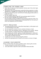
light sources may reflect on the face of the monitor. Place the monitor just below eye level. · Handle with care when transporting the monitor. · Refrain from giving shock or scratch to the screen, as screen is fragile. CLEANING YOUR MONITOR Please carefully follow the below guidelines when cleaning - Acer A231H | User Manual - Page 7
following items are present when you unpack the box, and save the packing materials in case you will need to ship or transport the monitor in future. · LCD Monitor · AC Power Cord · D-Sub Cable (Optional) · DVI Cable (Optional) · Audio Cable (Optional) · User Manual · Quick Start Guide EN-5 - Acer A231H | User Manual - Page 8
cloth to avoid scratching the screen. Install: Align the base with the stand and push the base towards the top of the monitor. Remove: Depress the release hooks as indicated first before removing the base and follow the arrow direction to remove it. SCREEN POSITION ADJUSTMENT In oder to optimize - Acer A231H | User Manual - Page 9
system if your system also supports DDC protocol. The DDC (Display Data Channel) is a communication protocol through which the monitor automatically informs the host system about its capabilities, for example, supported resolutions and corresponding timing. The monitor supports DDC2B standard. EN-8 - Acer A231H | User Manual - Page 10
Ground DDC-return R-Ground G-Ground B-Ground PIN NO. 9. 10. 11. 12. 13. 14. 15. DESCRIPTION +5V Logic Ground Monitor Ground DDC-Serial Data H-Sync V-Sync DDC-Serial Clock 19-pin color display signal cable* 1917151311 9 7 5 3 1 1816141210 8 6 4 2 PIN No. Description 1 TMDS Data2+ 3 TMDS - Acer A231H | User Manual - Page 11
Data0+ 7. DDC Data 19. TMDS Data 0/5 Shield 8. NC 20. NC 9. TMDS Data1- 21. NC 10. TMDS Data1+ 22. TMDS Clock Shield 11. TMDS Data 1/3 Shield 23. TMDS Clock+ 12. NC 24. DDC TMDS Clock- EN-10 - Acer A231H | User Manual - Page 12
Standard Timing Table Mode Resolution 1 VGA 640x480 60 Hz 2 MAC 640x480 66.66 Hz 3 VESA 720x400 70 Hz 4 SVGA 800x600 56 Hz 5 SVGA 800x600 60 Hz 6 XGA 1024x768 60 Hz 7 - Acer A231H | User Manual - Page 13
to the monitor, then to a properly grounded AC outlet. 4. Power-ON Monitor and Computer Power-ON the monitor first, then power-ON the computer. This sequence is very important. 5. If the monitor still does not function properly, please refer to the troubleshooting section to diagnose the problem. EN - Acer A231H | User Manual - Page 14
key to select from different video sources that may be connected to your monitor. (a) VGA input (b) DVI input (c) HDMI input As you cycle through the sources you will see the following messages on right top side of screen to indicate currently selected input source. It may take 1 or 2 seconds for - Acer A231H | User Manual - Page 15
the Acer eColor Management OSD and access the scenario modes Step 2: Press " " or " " to select the mode Step 3: Press " AUTO " Key to confirm the mode and exit the eColor menu. Features and Benefits Main Menu icon Sub Menu icon Sub Menu item Description N/A User mode User defined. Settings - Acer A231H | User Manual - Page 16
reference only. Actual product specifications may vary. The OSD can be used for adjusting the settings of your LCD Monitor. Press the MENU key to open the OSD. You can use the OSD to adjust the picture quality, OSD position and general settings. For advanced settings, please refer to following - Acer A231H | User Manual - Page 17
Adjusting the OSD position 1 Press the MENU key to bring up the OSD. 2 Using the directional keys, select OSD from the on screen display. Then navigate to the feature you wish to adjust. EN-16 - Acer A231H | User Manual - Page 18
Adjusting the setting 1 Press the MENU key to bring up the OSD. 2 Using the / keys, select Setting from the OSD. Then navigate to the feature you wish to adjust. 3 The Setting menu can be used to adjust the screen Menu Language and other important settings. EN-17 - Acer A231H | User Manual - Page 19
Product information 1 Press the MENU key to bring up the OSD. 2 Using the / keys, select Information from the OSD. Then the basic information of LCD monitor will show up for current input. EN-18 - Acer A231H | User Manual - Page 20
Before sending your LCD monitor for servicing, please check the troubleshooting list below to see if you can self-diagnose the problem. (VGA Mode) Problems Current Status Remedy LED ON · Using OSD, adjust brightness and contrast to maximum or reset to their default settings. LED OFF · Check - Acer A231H | User Manual - Page 21
(DVI Mode) Problems Current Status Remedy LED ON · Using OSD, adjust brightness and contrast to maximum or reset to their default settings. LED OFF · Check the power switch. No Picture · Check if AC power cord is properly connected to the monitor. LED displays amber color · Check if video - Acer A231H | User Manual - Page 22
Switzerland Hereby declare that: Product: Trade Name: Model Number: SKU Number: LCD Monitor Acer A231H A231H xxxxxx ((("x" = 0~9, a ~ z, A ~ Z or B lank) 2009/125/EC with regard to establishing a framework for the setting of ecodesign requirements for energy-related product. Year to begin - Acer A231H | User Manual - Page 23
Manufacturer /Importer is responsible for this declaration: Product Name: LCD Monitor Main Model Number: A231H Series Model Number: Name of Responsible Party: A231H xxxxxx (""" x" === 0~~~ 9, a~~~ z, A~~~ Z or Blank) Acer America Corporation Address of Responsible Party: 333 West San Carlos
-
 1
1 -
 2
2 -
 3
3 -
 4
4 -
 5
5 -
 6
6 -
 7
7 -
8
-
9
-
10
-
11
-
12
-
13
-
14
-
15
-
16
-
17
-
18
-
19
-
20
-
21
-
22
-
23
 |
 |

TABLE OF CONTENTS
Special notes on LCD monitors
..................................................
1
Information for your safety and
comfort
..................................
2
Unpacking
...................................................................................
5
Attaching/Removing the base
...................................................
Screen position adjustment
........................................................
6
Connecting the power cord
.......................................................
7
Safety precaution
.......................................................................
7
Cleaning your monitor
...............................................................
7
Power saving
...............................................................................
8
DDC
..............................................................................................
8
Connector Pin Assignment
.........................................................
9
Standard Timing Table
..................................................................
11
Installation
.....................................................................................
12
User controls
..................................................................................
13
Troubleshooting
............................................................................
19
.6