Acer AL1951 AL1951 User's Guide
Acer AL1951 Manual
 |
View all Acer AL1951 manuals
Add to My Manuals
Save this manual to your list of manuals |
Acer AL1951 manual content summary:
- Acer AL1951 | AL1951 User's Guide - Page 1
5 ADJUSTING THE VIEWING ANGLE 6 OPERATING INSTRUCTIONS 7 GENERAL INSTRUCTIONS 7 HOW TO ADJUST A SETTING 9 ADJUSTING THE PICTURE 10-11 PLUG AND PLAY 12 TECHNICAL SUPPORT(FAQ 13-14 ERROR MESSAGE & POSSIBLE SOLUTION ------- 15 APPENDIX 16 SPECIFICATIONS 16-17 FACTORY PRESET TIMING TABLE 18 - Acer AL1951 | AL1951 User's Guide - Page 2
responsible for compliance could void the user's authority to operate the equipment. 2. Shielded interface cables and AC power cord, if any, must be the monitor to rain or moisture. Dangerously high voltages are present inside the monitor. Do not open the cabinet. Refer servicing to qualified - Acer AL1951 | AL1951 User's Guide - Page 3
not overload power strips and extension cords. Overloading can result in fire or electric shock. z Never push any object into the slot on the monitor cabinet. It could short circuit parts causing a fire or electric shock. Never spill liquids on the monitor. z Do not attempt to service the monitor by - Acer AL1951 | AL1951 User's Guide - Page 4
by changing the image or turning off the Power Switch for hours. BEFORE YOU OPERATE THE MONITOR FEATURES • 48cm(19") TFT Color LCD Monitor • Crisp, Clear Display for Windows • Recommened Resolutions: 1280 X 1024 @60Hz • EPA ENERGY STAR® • Dual Input (DVI + Analog) (Only Dual-Input Model) • Ergonomic - Acer AL1951 | AL1951 User's Guide - Page 5
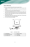
user adjustment is required.) 3. Connect the AC-power cord into your LCD monitor's DC-power-input. The ACpower cord may be connected to either a wall power outlet or the power outlet socket on your PC, depending on the type of power cord supplied with your LCD monitor. NOTES A certified power supply - Acer AL1951 | AL1951 User's Guide - Page 6
port). 5. Plug the power cable of your monitor into a nearby outlet. Plug the other end of the power cord into the power adapter. 6. Turn on your monitor and computer. Figure 1 Connecting Cables 1. D-SUB Cable 2. DC-Jack Power Cable 3. AC Power Cord 4. External Adapter 5. DVI Cable 6. Audio cable - Acer AL1951 | AL1951 User's Guide - Page 7
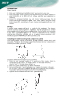
please notice that the rear obliquity of the monitor must not be over 15° when you adjust it, otherwise the machine may be inclined. Figure 2 NOTES • Do not touch the LCD screen when you change the angle. It may cause damage or break the LCD screen. • Careful attention is required not to catch - Acer AL1951 | AL1951 User's Guide - Page 8
OPERATING INSTRUCTIONS GENERAL INSTRUCTIONS Press the power button to turn the monitor on or off. The other control buttons are located at front panel of the monitor (See Figure 3). By changing these settings, the picture can be adjusted to your personal preferences. • The power cord should be - Acer AL1951 | AL1951 User's Guide - Page 9
FRONT PANEL CONTROL • Power Button: Press this button to turn the monitor ON or OFF, And display the monitor's state. • Power Indicator: Blue - Power On mode. Orange - Power off. • MENU / ENTER : Activate OSD menu when OSD is OFF or activate/de-activate adjustment function when OSD is ON or - Acer AL1951 | AL1951 User's Guide - Page 10
HOW TO ADJUST A SETTING 1. Press the MENU-button to activate the OSD window. 2. Press < or > to select the desired function. 3. Press the MENU-button to select the function that you want to adjust. 4. Press < or > to change the settings of the current function. 5. To exit and save, select the exit - Acer AL1951 | AL1951 User's Guide - Page 11
). Adjust picture Clock (available in Analog V. Position mode only). N/A Warm Set the color temperature to warm white. N/A Cool Set the color temperature to cool white. User /Red User/Green Adjusts Red/Green/Blue intensity - Acer AL1951 | AL1951 User's Guide - Page 12
picture. N/A Analog Select input signal from analog (D-Sub) (only DualInput Model) N/A Digital N/A Information N/A Reset Select input signal from digital (DVI) Show the resolution, H/V frequency and input port of current iput timing. Clear each old status of Auto-configuration and set the color - Acer AL1951 | AL1951 User's Guide - Page 13
MONITOR TO OPERATE PROPERLY, THERE MUST BE A VIDEO INPUT SIGNAL. This monitor meets the Green monitor standards as set by the Video Electronics Standards Association (VESA monitor's internal power supply consumption. After the video input signal is restored, full power is restored and the display is - Acer AL1951 | AL1951 User's Guide - Page 14
TECHNICAL SUPPORT (FAQ) Problem & Question Possible Solution Power LED is not on *Check if the Power Switch is in the ON position *Power Cord should be connected No Plug . Missing one of the primary *Inspect the monitor's video cable and colors (RED, GREEN, or make sure that none of the pins - Acer AL1951 | AL1951 User's Guide - Page 15
Screen image is not centered or sized *Adjust pixel frequency (CLOCK) and properly. FOCUS or press hot-key (AUTO) Picture has color defects *Adjust RGB color or select color (white does not look white) temperature Horizontal or vertical disturbances on *Use win 95/98 shut-down mode the - Acer AL1951 | AL1951 User's Guide - Page 16
-cable is properly connected , If the connector is loose, tighten the connector's screws. 2. Check the signal -cable connection pins for damage. INPUT NOT SUPPORT : Your computer has been set to unsuitable display mode ,set the computer to display mode given in the following table(See page 18). 15 - Acer AL1951 | AL1951 User's Guide - Page 17
APPENDIX SPECIFICATIONS Driving system TFT Color LCD LCD Panel Size 48cm(19") Pixel pitch 0.294mm( H )x 0.294mm( V ) Brightness - 80KHz V-Frequency 55-75Hz Display Colors 16.2M Colors Dot Clock 135MHz Max. Resolution 1280 x 1024 @75Hz Plug & Play VESA DDC2BTM EPA ENERGY STAR® ON - Acer AL1951 | AL1951 User's Guide - Page 18
-Input Model) • Language • Auto configuration (only Analog-input Model) • (Warm) Color • (Cool)Color • RGB Color temperature • Reset • OSD position . timeout • Display information • Exit 50 Watts Rated Power 1.5W rms (Per channel) CUL, FCC, VCCI, CCC, MPR II, CE, TÜV/GS, TCO'99, UL, ISO13406-2 17 - Acer AL1951 | AL1951 User's Guide - Page 19
Preset Display Modes VIDEO MODE RESOLUTION VGA 640 × 480 640 × 480 HORIZONTAL FREQUENCY(kHz) 31.469 37.500 VERTICAL FREQUENCY(Hz) 59.940 75.000 SVGA 800 × 600 800 × 600 37.879 46.875 60.317 75.000 VESA XGA 1024 × 768 1024 × 768 48.363 56.476 60.004 70.069 1024 × 768 - Acer AL1951 | AL1951 User's Guide - Page 20
6. 7. 8. 15 - Pin Color Display Signal Cable DESCRIPTION PIN NO. Red 9. Green 10. Blue 11. Monitor Ground 12. DDC-return 13. R-Ground TMDS Data4+ 13. TMDS Data3+ 21. TMDS Data5+ 6. DDC Clock 14. +5V Power 22. TMDS Clock Shield 7. DDC Data GND(return for 15. +5V 23. TMDS Clock
-
 1
1 -
 2
2 -
 3
3 -
 4
4 -
 5
5 -
 6
6 -
 7
7 -
8
-
9
-
10
-
11
-
12
-
13
-
14
-
15
-
16
-
17
-
18
-
19
-
20
 |
 |

.
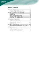
TABLE OF CONTENTS
FOR YOUR SAFETY -------------------------------------------------- 1
SAFETY PRECAUTIONS -------------------------------------- 2
SPECIAL NOTES ON LCD MONITORS ------------------- 3
BEFORE YOU OPERATE THE MONITOR --------------------- 3
FEATURES -------------------------------------------------------- 3
PACKING LIST --------------------------------------------------- 3
INSTALLATION INSTRUCTIONS --------------------------- 4
CONTROLS AND CONNECTORS -------------------------- 5
ADJUSTING THE VIEWING ANGLE ----------------------- 6
OPERATING INSTRUCTIONS ------------------------------------- 7
GENERAL INSTRUCTIONS ---------------------------------- 7
HOW TO ADJUST A SETTING ------------------------------ 9
ADJUSTING THE PICTURE -----------------------------
10-11
PLUG AND PLAY -----------------------------------------------
12
TECHNICAL SUPPORT(FAQ) --------------------------------
13-14
ERROR
MESSAGE & POSSIBLE
SOLUTION -------
15
APPENDIX -------------------------------------------------------------
16
SPECIFICATIONS ------------------------------------------ 16-17
FACTORY PRESET TIMING TABLE ---------------------
18
CONNECTOR PIN ASSIGNMENT ------------------------
19