Acer Altos S200F User Manual
Acer Altos S200F Manual
 |
View all Acer Altos S200F manuals
Add to My Manuals
Save this manual to your list of manuals |
Acer Altos S200F manual content summary:
- Acer Altos S200F | User Manual - Page 1
Altos S205F / S200F User's Manual Issue 1.0 1 May, 2004 • Acer and the Acer logo are registered trademarks of Acer Incorporated. Other company's product names or trademarks are used herein for identification purposes only and belong to their respective companies. • All other names, brands, products - Acer Altos S200F | User Manual - Page 2
or changes. Such changes will be incorporated in new editions of this manual or supplementary documents and publications. This company makes no representations or warranties, , photocopy, recording, or otherwise, without the prior written permission of Acer Incorporated. Issue 1.0 1 May, 2004 ii - Acer Altos S200F | User Manual - Page 3
15 1.5.5 Power Cord ...15 1.5.6 Environment ...16 1.5.7 Altos S205F RAID I/O Module Specification 17 1.5.8 Altos S200F JBOD I/O Module Specification 17 1.5.9 Drive Carrier Module Specification 18 1.5.10 SCSI Enclosure Services (SES) Support 18 2 Getting Started ...19 2.1 Introduction ...19 iii - Acer Altos S200F | User Manual - Page 4
...26 2.6.1 Connecting Multiple Enclosures 27 2.7 I/O Module Installation ...29 2.7.1 Parts Check List ...29 2.7.2 Procedure ...30 2.8 Altos S205F Drive Enclosure Device Addressing ...31 2.9 Altos S200F Drive Enclosure Device Addressing ...32 2.10 Drive Carrier Configuration 34 2.10.1 Planning and - Acer Altos S200F | User Manual - Page 5
What is in this manual This user's manual gives you step-by-step instructions on how to install, configure and connect a Altos S205F / S200F storage subsystem to your host computer system, and how to use and maintain the system. Who should use this manual This user's manual e assumes that you have - Acer Altos S200F | User Manual - Page 6
Acer S205F / S200F User's Manual Properly shielded and grounded cables and connectors must be used in Caution Label: - Do not operate with modules missing - Spin down time 30 seconds • An Alto S205F / S200F enclosure can weigh up to 37kg (81lb). Do not try to lift it by yourself. Chassis Warning - Acer Altos S200F | User Manual - Page 7
PSU/Cooling module, they are not designed to support the weight of the populated enclosure. • In order to comply with applicable safety, emission and thermal requirements no covers should be removed and all bays must be fitted with plug-in modules. • The Alto S205F / S200F unit must only be operated - Acer Altos S200F | User Manual - Page 8
Acer S205F / S200F User's Manual • The power connection should always be disconnected prior is incorrectly replaced. • Dispose of used batteries in accordance with the manufacturer's instructions and National regulations. Rack System Precautions The following safety requirements must be considered - Acer Altos S200F | User Manual - Page 9
recommended that you fit and check a suitable anti-static wrist or ankle strap and observe all conventional ESD precautions when handling Altos S205F / S200F Storage System plug-in modules and components. Avoid contact with backplane components and module connectors, etc. Data Security • Power down - Acer Altos S200F | User Manual - Page 10
Acer S205F / S200F User's Manual • Do not abandon Altos S205F/S200F Storage System enclosure for use with the drive locks). Related Documentation • Altos S200F Storage System Quick Installation Guide • Altos S205F Storage System Quick Installation Guide • Altos RAIDWatch User's Guide • Altos S205F - Acer Altos S200F | User Manual - Page 11
Revision History Version Date 1.0 1 May, 2004 Description of Change Initial Release Preface xi - Acer Altos S200F | User Manual - Page 12
Acer S205F / S200F User's Manual xii - Acer Altos S200F | User Manual - Page 13
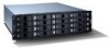
Chapter 1 Introduction 1.1 The Altos S205F / S200F Storage System . Introduction Figure 1-1 Altos S205F / S200F Storage System 1 - Acer Altos S200F | User Manual - Page 14
Altos S205F / S200F User's Manual 1.2 The Enclosure Core Product The Altos S205F / S200F Storage System design concept is based on a subsystem together with a set of plug-in modules. The Altos S205F / S200F Storage System subsystem as supplied comprises: • Chassis and Backplane with integral - Acer Altos S200F | User Manual - Page 15
(Front) * SES Drives (there must be a drive present in Bay 1/1 or 4/4 to enable SES communications to operates). Figure 1-3 Altos S205F Enclosure Chassis (Rear) Figure 1-4 Altos S200F Enclosure Chassis (Front) * SES Drives (there must be a drive present in Bay 1/1 or 4/4 to enable SES communications - Acer Altos S200F | User Manual - Page 16
Altos S205F / S200F User's Manual 1.2.2 Tower Option An optional tower kit is available, which can be fitted to the rack chassis described here. Figure 1-6 Altos S205F / S200F Storage System Tower Option 1.3 The Plug-in Modules Note An Altos S205F / S200F Storage System Enclosure requires the - Acer Altos S200F | User Manual - Page 17
Power Supply/Cooling module (see Figure 1-7) indicate the status of the PSU and the fans. 1.3.1.2 Multiple Power Supply/Cooling Modules The Altos S205F / S200F Storage System must always be operated with two Power Supply/Cooling modules fitted. The two Power Supply/Cooling modules operate together - Acer Altos S200F | User Manual - Page 18
Altos S205F / S200F User's Manual 1.3.2 Operators Panel Supplied as an integral part of the Enclosure core product, a typical Operators (Ops) Panel is shown in Figure 1-8. Figure 1-8 Ops Panel The Ops - Acer Altos S200F | User Manual - Page 19
Introduction Table 1-1 Altos S205F Ops Panel Switch Functions (Default settings at 2Gb/s) Switch Number *See Sw 11 Function 1 Not Used 2 Not Used 3 Hub Mode Recommended Setting Definition OFF Not - Acer Altos S200F | User Manual - Page 20
Altos S205F / S200F User's Manual Table 1-2 Altos S200F Ops Panel Switch Functions (Default settings at 2Gb/s) Figure 1-9). The controller supports RAID levels 0, 1, 0+1, 3, 5, 10, 30 and 50. The plug-in I/O modules have been designed for integration into a Altos S205F / S200F Storage System - Acer Altos S200F | User Manual - Page 21
Introduction Table 1-3 Altos S205F RAID I/O Module LEDs LED Functions Color Description Battery Fail Amber is active. System Amber When ON this LED denotes that the Controller is failed or SES Services card is failed. Cache Active Amber When ON this LED denotes the following status: • When - Acer Altos S200F | User Manual - Page 22
Altos S205F / S200F User's Manual Figure 1-9 Altos S205F RAID I/O Module The Altos S205F RAID I/O Module operates at 1 or 2 Gb/s. • One external port for expansion to further protection and is connected to the RAID I/O Module by flying lead. Figure 1-10 Altos S200F JBOD I/O Module 10 not used - Acer Altos S200F | User Manual - Page 23
Introduction Figure 1-11 Altos S205F / S200F Storage System Enclosure with I/O Modules and AC PSUs Installed 1.3.4 Supported Configuration Tools • RAIDWatch • R232 Management User Interface (MUI) 1.3.5 Drive Carrier Module The Drive Carrier Module comprises a hard disk mounted in a carrier. - Acer Altos S200F | User Manual - Page 24
Altos S205F / S200F User's Manual Figure 1-12 Drive Carrier Module 1.3.5.1 SATA Transition Card For Serial ATA use a Transition card is attached to the rear of each drive, this provides a SCA-2 - Acer Altos S200F | User Manual - Page 25
Introduction Figure 1-13 Anti-tamper Lock 1.3.6 Dummy Carrier Modules Dummy carrier modules are provided for fitting in all unused drive bays. They are designed as integral drive module front caps with handles and must be fitted to all unused drive bays to maintain a balanced airflow. 1.3.7 - Acer Altos S200F | User Manual - Page 26
Altos S205F / S200F User's Manual 1.5 Altos S205F / S200F Storage System Technical Specification 1.5.1 Dimensions Rack Enclosure Height Width across mounting flange feet) Depth inches 22.27 10.22 23.24 millimeters 501 230 523 Table 1-5 Altos S205F / S200F Storage System Chassis Dimensions 14 - Acer Altos S200F | User Manual - Page 27
1.5.2 Weight Maximum Configuration Empty Enclosure (Rack) PSU/Cooling Module Controller I/O Module Tower Conversion Kit Rack mount: Tower: 37kg (81lb) 40kg (88lb) 9kg (19.8lb) 4kg (8.8lb) 0.9kg (1.98lb) 3kg (6.6lb) 1.5.3 AC Power (450W PSU) Voltage Range Voltage Range Selection Frequency Inrush - Acer Altos S200F | User Manual - Page 28
Altos S205F / S200F User's Manual 1.5.6 Environment Table 1-6 Ambient Temperature and Humidity Temperature Range Relative Humidity Max. Wet Bulb Operational 5°C to 40°C 20% to 80% non-condensing 23 °C NonOperational 0°C to +50°C 8% - Acer Altos S200F | User Manual - Page 29
Introduction 1.5.7 Altos S205F RAID I/O Module Specification Speed Mounting Connectors 1.5Gb/s cable Power Dissipation 5A @ 3.3V, 1A @ 5V RAID Levels supported 0, 1, 0+1, 3, 5, 10, 30, and 50 1.5.8 Altos S200F JBOD I/O Module Specification Speed Mounting Connectors Power Dissipation 1.5Gb/s - Acer Altos S200F | User Manual - Page 30
Altos S205F / S200F User's Manual 1.5.9 Important Drive Carrier Module Specification Please contact your supplier for details of approved drives. Operating the Altos S205F Modules) 17 Watts maximum 1.5.10 SCSI Enclosure Services (SES) Support The enclosure has a sophisticated self-monitoring and - Acer Altos S200F | User Manual - Page 31
connecting up the Altos S205F / S200F Storage S205F Storage System Configuration Module Location Drive Bays ALL drive bays must be fitted with either a drive carrier module or a dummy carrier, no bays should be left completely empty. All drive carrier modules provide SES Management Services - Acer Altos S200F | User Manual - Page 32
Acer S205F / S200F User's Manual Table 2-1 Altos S205F Storage System Configuration Module Location Blank I/O Module If only one RAID I/O moudle is installed a blank module must be fitted in the unused bay. No bays - Acer Altos S200F | User Manual - Page 33
Getting Started Figure 2-1 Altos S205F Module locations * SES Drives (there must be a drive present in Bay 1/ 1 or 4/4 to enable SES communications to operates). Figure 2-2 Altos S200F Module locations * SES Drives (there must be a drive present in Bay 1/ 1 or 4/4 to enable SES communications to - Acer Altos S200F | User Manual - Page 34
Acer S205F / S200F User's Manual 2.2.1 Enclosure Bay Numbering Convention The enclosure bay numbering convention is shown the system to operate and provide SES Management Services. 2.3 Enclosure Installation Procedures Caution Warning The Altos S205F / S200F Storage System enclosure with all - Acer Altos S200F | User Manual - Page 35
Getting Started 2.3.2.1 Parts Check List • Rack Mounting Rail Kit. 2.3.2.2 Installation Procedure Please see detail drawings supplied with the rack mounting rail kit for assembly details. Figure 2-3 Rack Mounting Rail Kit 2.3.3 Chassis Installation 2.3.3.1 Parts Check List • Chassis (complete with - Acer Altos S200F | User Manual - Page 36
Acer S205F / S200F User's Manual 2.4 Power Supply/Cooling Module Installation Warning Install in (Rear Bay 1) of the enclosure in an "upside down* orientation. 3 Cam the module home by manually closing the PSU handle (Figure 2-7). A click should be heard as the handle latches engage. 4 Connect - Acer Altos S200F | User Manual - Page 37
Getting Started Figure 2-5 AC Power Supply/Cooling Module - Handle in Open Position Figure 2-6 Installing an AC Power Supply Cooling Module (1) 25 - Acer Altos S200F | User Manual - Page 38
Acer S205F / S200F User's Manual Figure 2-7 Installing an AC Power Supply Cooling Module (2) 2.5 RAID and JBOD I/O Module Configurations Important Please refer to section 2.10 for information on SATA drive configurations. 2.5.1 Internal Loop Structures The Altos S205F / S200F Storage System - Acer Altos S200F | User Manual - Page 39
not have a connection to the 3.3V supply (pins 15 and 16). Note Expansion enclosures are Altos S200F Storage System. A maximum of 6 Altos S200Fs can be attached to an Altos S205F Storage System enclosure and a typical expansion configuration is shown in Figure 2-8,Figure 2-9 . Figure 2-8 Single - Acer Altos S200F | User Manual - Page 40
Acer S205F / S200F User's Manual Figure 2-9 Dual loops connection Each connection can see all the drives in the enclosure. J7 jumper of Altos S200F is open. 28 - Acer Altos S200F | User Manual - Page 41
be installed in rear bay 4 and a Blank I/O module fitted in the unused bay. • Two RAID I/O Modules ,or one RAID I/O Module with one Blank I/O module for Altos S205F • Two JBOD I/O Modules ,or one JBOD I/O Module with one Blank I/O module for - Acer Altos S200F | User Manual - Page 42
Acer S205F / S200F User's Manual 2.7.2 Procedure Check for damage especially to the interface connector, Controller module into the enclosure until the latch engages automatically. 3 Cam the module home by manually closing the latches (see Figure 2-12). 4 A click should be heard as the latch engages. - Acer Altos S200F | User Manual - Page 43
Getting Started 2.8 Altos S205F Drive Enclosure Device Addressing Each enclosure has 16 drives. The SEL_ID of each drive is determined by the device slot (0-15) in which it is - Acer Altos S200F | User Manual - Page 44
Acer S205F / S200F User's Manual Notes 1 Drives are numbered row/column. ) Table 2-4 2 Module 8 of the SEL_ID) unless there are two active PSUs when they all start immediately. 2.9 Altos S200F Drive Enclosure Device Addressing Each enclosure has 16 drive bays. The SEL_ID of each drive is - Acer Altos S200F | User Manual - Page 45
Switch Number Function Recommended Setting On Off Off Off 11 SOFT SELECT On 12 Not Used Off Definition * Mode 2 (not supported * Mode 3 (not supported) Selects functions using the hardware switches Notes 1 ON = switch to the Right, OFF = switch to the Left. Table 2-6 Mode 0 Drive - Acer Altos S200F | User Manual - Page 46
Acer S205F / S200F User's Manual Table 2-7 Drive Slot Arrangement: Enclosure Front View Row/Column 1/# 2/# 3/# 4/# #/3 paths. Warning When planning your system configuration, please remember that: • All Altos S205F / S200F Storage System enclosure drive bays must be filled with either a - Acer Altos S200F | User Manual - Page 47
Getting Started 2.11.2 Procedure 1 Important Release the carrier handle, by pressing the latch in the handle towards the right and insert the carrier into the enclosure (Figure 2-13). For a Rack Mounted System: Ensure that the carrier is orientated so that the drive is uppermost and the handle - Acer Altos S200F | User Manual - Page 48
Acer S205F / S200F User's Manual Figure 2-14 Installing a SATA Drive Carrier Module (2) Figure 2-15 Installing an SATA Drive Carrier Module (3) 36 - Acer Altos S200F | User Manual - Page 49
Getting Started 2.11.3 Dummy Carrier Modules Any unused drive bays must be fitted with a dummy carrier module. 2.11.4 Engaging the Anti-tamper Locks The anti-tamper locks are fitted in the drive carrier handles and are accessed through the small cutout in the latch section of the handle. Drives - Acer Altos S200F | User Manual - Page 50
Acer S205F / S200F User's Manual 2.12.2 Procedure 1 Attach the power cord to the Power Supply/ to the rack distribution and the enclosure. Warning • If a direct connection is made with the Altos S205F / S200F Storage System power cord, ensure that it is connected to the enclosure. Some electrical - Acer Altos S200F | User Manual - Page 51
LEDs on the Ops Panel should be lit Green at power up to indicate that the system is functioning correctly. If any show Amber then a problem exists and please contact certificated supplier. If AC power is lost for any reason, on restoration of power the enclosure will re-start automatically - Acer Altos S200F | User Manual - Page 52
Acer S205F / S200F User's Manual Table 3-1 PSU LEDs AC PSU PSU Good AC input Fail Fan Fault DC Output Fail Green Amber Amber Amber 3.3 Ops Panel LEDs The Ops Panel LEDs fault and status conditions are defined in Table 3-2 and shown in Figure 3-1. Hub Mode LED (for Altos S205F only) Figure 3-1 - Acer Altos S200F | User Manual - Page 53
Altos S205F only - - Invalid Address Not Used - - 3.4 Starting the Drives Unless otherwise selected during installation, all drives in the enclosure should automatically start their motors. If this has not occurred one of the following conditions may exist: • There may be a power problem - Acer Altos S200F | User Manual - Page 54
Acer S205F / S200F User's Manual 42 - Acer Altos S200F | User Manual - Page 55
and the integrated disk controller and drive. The ATA "bus" only supports two devices - master and slave. Attribute Setting that controls access to 64K indicates 65,536 bytes or characters. Cable Throughout this Altos S205F / S200F User's Manual this term is used in accordance with the preferred US - Acer Altos S200F | User Manual - Page 56
running the host computer. For example, on PCs it is often Windows® 2000 or Windows® NT. Power Cord Throughout this Altos S205F / S200F Storage System user's manual this term is used in accordance with the preferred US context of: "an insulated flexible electric wire fitted with connectors at each - Acer Altos S200F | User Manual - Page 57
Index a AC PSU 2, 4, 24 Alarm Mute push-button 13 anti-static wrist or ankle strap 22 anti-tamper lock 12, 37 Audible Alarm 6, 13 b Backplane 2, 22, 23 bay 2, 19, 20, 22 c chassis 2, 23 d Disk 41 disk drive 2, 22 Disk Drives LEDs 41 drive array 26 drive carrier 35 drive carrier handles 12 Drive - Acer Altos S200F | User Manual - Page 58
Acer S205F / S200F User's Manual v Visible and Audible Alarms 13 46
-
 1
1 -
 2
2 -
 3
3 -
 4
4 -
 5
5 -
 6
6 -
 7
7 -
8
-
9
-
10
-
11
-
12
-
13
-
14
-
15
-
16
-
17
-
18
-
19
-
20
-
21
-
22
-
23
-
24
-
25
-
26
-
27
-
28
-
29
-
30
-
31
-
32
-
33
-
34
-
35
-
36
-
37
-
38
-
39
-
40
-
41
-
42
-
43
-
44
-
45
-
46
-
47
-
48
-
49
-
50
-
51
-
52
-
53
-
54
-
55
-
56
-
57
-
58
 |
 |

Altos S205F / S200F
User’s Manual
Issue 1.0
1 May, 2004
•
Acer and the Acer logo are registered trademarks of Acer Incorporated. Other company's
product names or trademarks are used herein for identification purposes only and belong to
their respective companies.
•
All other names, brands, products or services are trademarks or registered trademarks of their
respective companies.