Acer Altos S300 User Manual
Acer Altos S300 Manual
 |
View all Acer Altos S300 manuals
Add to My Manuals
Save this manual to your list of manuals |
Acer Altos S300 manual content summary:
- Acer Altos S300 | User Manual - Page 1
Acer Altos S300 User's guide - Acer Altos S300 | User Manual - Page 2
Incorporated All Rights Reserved. Acer Altos S300 User's guide Changes may be made periodically to the information in this publication without obligation to notify any person of such revision or changes. Such changes will be incorporated in new editions of this manual or supplementary documents and - Acer Altos S300 | User Manual - Page 3
difficulties with a Acer Altos S300 system and is unable to resolve the problem via phone with Acer Technical Support a Return Material necessitated in whole or in part by catastrophe, fault or negligence of the user, improper or unauthorized use of the product, or use of the product in - Acer Altos S300 | User Manual - Page 4
costs for such replacement. Purchaser shall provide labor for removal of the defective product, shipping charges for return to Acer and installation of its replacement. On-site services are not a part of this warranty. Above warranties are subject to change without notice. Warranty claims must be - Acer Altos S300 | User Manual - Page 5
energy and, if not installed and used in accordance with the instructions, may cause harmful interference to radio communications. However, there is reception, which can be determined by turning the device off and on, the user is encouraged to try to correct the interference by one or more of the - Acer Altos S300 | User Manual - Page 6
Interference by Information Technology Equipment. If this equipment is used in a domestic environment, radio disturbance may arise. When such trouble occurs, the user may be required to take corrective actions. BSMI In a domestic environment this product may cause radio interference, in which case - Acer Altos S300 | User Manual - Page 7
Important safety instructions Read these instructions carefully. Save these instructions for future reference. 1. Follow all warnings and instructions marked on the kind on the product. 10. Do not attempt to service this product yourself, as opening or removing covers may expose you to dangerous voltage - Acer Altos S300 | User Manual - Page 8
when the operating instructions are followed. Adjust only those controls that are covered by the operating instructions since improper If the product exhibits a distinct change in performance, indicating a need for service. 12. Replace the battery with the same type as the product's battery - Acer Altos S300 | User Manual - Page 9
Important safety instructions vii 1 Introduction 1 About the Altos S300 series storage array 3 Features 4 Disk drive carrier 5 Power supplies 5 Cooling system 6 I/O modules 7 Enclosure Services Module 7 Terminating Services Module 8 Concentrator Services Module 8 2 Installation - Acer Altos S300 | User Manual - Page 10
x Dual CSM configuration 28 Dual concentrator services modules 28 Join/Split bus jumper 30 Powering on the Altos S300 series enclosure 31 Altos S300 series jumper settings 31 Powering on an AC enclosure 32 4 System monitoring 33 Overview 35 Environmental status (ES) block 36 - Acer Altos S300 | User Manual - Page 11
1 Introduction - Acer Altos S300 | User Manual - Page 12
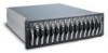
This chapter introduces the Altos S300 series of storage arrays. The main features are described along with a list of the options and configurations that are available. - Acer Altos S300 | User Manual - Page 13
series is a new concept in data storage that provides the optimum in investment protection and versatility. The Altos S300 series will meet the performance, capacity, and high availability needs of the widest variety of applications, such as video, imaging, prepress, data warehouse, OLTP, and - Acer Altos S300 | User Manual - Page 14
or two power supplies. • Failure indication of all Field Replaceable Units (FRU) via LEDs and audible alarm (with alarm mute button). • Disk drive hot plug support. • Auto-sense termination at end of bus (busses) if no cable present. • Auto bus split, if two cables are present. • Up to 10M of LVD - Acer Altos S300 | User Manual - Page 15
a one inch disk drive with support for 10K RPM drives and higher (15K). The Altos S300 series enclosure holds up to fourteen disk drive carriers. The disk drives can be hot swapped and the disk drive carriers provide for blind mating. Power supplies The Altos S300 series uses two AC power supplies - Acer Altos S300 | User Manual - Page 16
6 1 Introduction Cooling system Cooling is provided by the two Advanced Cooling Modules (ACMs) located at the rear of the enclosure. Each of the ACM units contain two variable speed fans. The enclosure requires four fans for normal operation, but will operate correctly when one fan fails to - Acer Altos S300 | User Manual - Page 17
information of the I/O modules, see page 20. The following sections will describe the modules and how they should be used. Enclosure Services Module The Enclosure Services Module (ESM) has three primary functions. It acts as a SCSI bus pass-through from external cabling to the internal busses - Acer Altos S300 | User Manual - Page 18
via the SCSI bus per the SCSI-3 Enclosure Services specification and also the SAF-TE specification. Concentrator Services Module The Concentrator Services Module (CSM) includes the same functionality as the other host. Note: For information on how to configure your Altos S300 series, see page 17. - Acer Altos S300 | User Manual - Page 19
2 Installation precautions - Acer Altos S300 | User Manual - Page 20
This chapter discusses the important safety instructions along with the electrical, mechanical and environmental precautions that need to be taken when installing the Altos S300 series enclosure. - Acer Altos S300 | User Manual - Page 21
11 ESD precautions Note: Before you install or operate the Altos S300 series enclosure, we recommend that you read the following instructions. Electrostatic discharge (ESD) can damage your processor, disk drives, expansion boards, and other components. Always observe the following precautions before - Acer Altos S300 | User Manual - Page 22
Safety precautions Always observe the following before you install or operate the Altos S300. For language translations of these statements refer to Appendix B. 1. This Disconnect both power supply inlets before opening this equipment for servicing. 8. Warning! Disconnect both power cables before - Acer Altos S300 | User Manual - Page 23
13 Unpacking and initial setup Carefully unpack the carton and remove the contents. If the exterior packaging or items are missing or damaged, contact your dealer immediately. Note: The disk drives are packaged in anti-static packaging, precautions must be observed prior to removal. - Acer Altos S300 | User Manual - Page 24
in an equipment rack, it is essential that the following guidelines are complied with, to ensure the safe and efficient operation of the system. The Altos S300 series can be installed in open or closed equipment racks, with a front width of 19 inch, by observing the environmental, electrical, and - Acer Altos S300 | User Manual - Page 25
twice the amount of current at start-up time as they do during steady state operation. Mechanical consideration When installing the Altos S300 series enclosure the following mechanical consideration must be applied. Mechanical loading Consideration should be given to the loading of the equipment - Acer Altos S300 | User Manual - Page 26
16 2 Installation precautions - Acer Altos S300 | User Manual - Page 27
3 Cabling and configuration - Acer Altos S300 | User Manual - Page 28
This chapter describes how to cable and configure your Altos S300 series enclosure. Detailed information on how and where to connect the cables will be provided along with information on the SCSI ID assignments. - Acer Altos S300 | User Manual - Page 29
series SCSI ID assignments The SCSI ID's for the Altos S300 series enclosure are hard set and cannot be changed in any way. The Altos S300 series enclosure has two modes of operation: Single (Joined) SCSI bus mode (1x14), and Dual (Split) SCSI bus mode (1x7 and 1x7). The I/O Modules are - Acer Altos S300 | User Manual - Page 30
20 3 Cabling and configuration I/O module LEDs There are LEDs mounted on the ESM, CSM and TSM. This section will explain what these LEDs mean. ESM/CSM LEDs Bus A Bus B Bus A ES Activity Bus B There are 5 LEDs in total on the ESM/CSM located as shown. The ES Activity LED shows, if the ES - Acer Altos S300 | User Manual - Page 31
21 Cabling the Altos S300 series enclosure The Altos S300 series enclosure can operate in three main configurations: Single ESM and TSM, Single CSM and TSM and Dual CSM configurations. This enclosure can sense the - Acer Altos S300 | User Manual - Page 32
22 3 Cabling and configuration Single ESM and TSM configuration This configuration can be cabled as either a Single (Joined) SCSI Bus or as a Dual (Split) SCSI Bus configuration. Cabling the single (joined) SCSI bus configuration One host cable is required for this configuration. The length of - Acer Altos S300 | User Manual - Page 33
23 The Bus A LED will be ON1 to indicate that all disks are on Bus A. The Environmental Services (ES) LED is ON for the TSM in this example to show that its ES block is the active block. Note: Both I/O modules are at - Acer Altos S300 | User Manual - Page 34
seven disks are on Bus A. The Bus B LED will be on for bottom connector to indicate that remaining seven disks are on Bus B. The Environmental Services (ES) LED is ON for both the ESM and TSM, to show that both of their ES blocks are active. Note: Both I/O modules are at - Acer Altos S300 | User Manual - Page 35
25 Single CSM and TSM Configuration This configuration can be cabled as either a Single (Joined) SCSI Bus or as a Dual (Split) SCSI Bus configuration. Cabling the single (joined) SCSI bus configuration One host cable is required for this configuration. The length of the host cable may be a maximum - Acer Altos S300 | User Manual - Page 36
26 3 Cabling and configuration The Bus A LED will be ON3 to indicate that all disks are on Bus A. The Environmental Services (ES) LED is ON for the TSM in this example to show that its ES block is the active block. Note: Both I/O modules are at - Acer Altos S300 | User Manual - Page 37
disks are on Bus A. The Bus B LED will be on for bottom connector to indicate that the remaining seven disks are on Bus B. The Environmental Services (ES) LED is ON for both the CSM and TSM, to show that both of their ES blocks are active. Note: Both I/O modules are at - Acer Altos S300 | User Manual - Page 38
3 Cabling and configuration Dual CSM configuration For this dual CSM configuration, there must be a Concentrator Services Module (CSM) installed in both I/O Option Slots. Dual concentrator services modules Four host cables are required for this configuration. These cables must not exceed 25 meters - Acer Altos S300 | User Manual - Page 39
To Cluster 2 Master Host To Cluster 1 Master Host Bus A Bus B CSM 1 2 Mute I 0 I 0 29 To Cluster 1 Slave Host To Cluster 2 Slave Host 1 2 Bus B Bus A CSM SCSI ID Assignments shown from front of enclosure In this configuration the SCSI bus is split, with each of the connectors attached to a host. - Acer Altos S300 | User Manual - Page 40
30 3 Cabling and configuration Join/Split bus jumper The ESM/CSM has a jumper located on it that forces the SCSI bus into joined or split mode. This jumper is located on the ESM/CSM PCB at location JP10. To access the jumper: 1. Remove the ESM/CSM from the enclosure. 2. Remove the top cover from - Acer Altos S300 | User Manual - Page 41
determine how the enclosure powers up and how the disk drives spin up. The following section describe the jumper settings. Altos S300 series jumper settings The Altos S300 series enclosure jumpers are located on the I/O Modules (ESM and CSM). By installing or removing these jumpers the following - Acer Altos S300 | User Manual - Page 42
I 0 I 0 Mute Insert Power cords into power connectors 3. Power on the host system and the Altos S300 series enclosure will power on also. Note: Powering off all the attached host systems will power off the Altos S300 series enclosure also. Refer to "Power up" on page 31 (jumper JP13). Warning! This - Acer Altos S300 | User Manual - Page 43
4 System monitoring - Acer Altos S300 | User Manual - Page 44
This chapter describes the devices used to monitor the Altos S300 Series. The location of the monitoring LEDs and how to interpret them is provided. - Acer Altos S300 | User Manual - Page 45
Modules (ACM), power supply modules, and enclosure front LED panel. The enclosure status is monitored by the Environmental Status (ES) block of the Altos S300 series. The Environmental Status block is built into the I/ O Modules (ESM, CSM and TSM). All these monitoring devices are discussed in the - Acer Altos S300 | User Manual - Page 46
Module The I/O Modules can be inserted into either I/O slot The I/O Modules can be inserted into either I/O slot. I/O Module A fully configured Altos S300 series enclosure will include two ES blocks, one located on each I/O Module. Each ES block will continuously monitor the enclosure. If the - Acer Altos S300 | User Manual - Page 47
37 • Two line serial buses for communication to all components. • Temperature sensor. • Failover logic to communicate with the other ES module. - Acer Altos S300 | User Manual - Page 48
38 4 System monitoring Alarm buzzer mute The alarm buzzer can be muted by pressing the alarm mute button located on the rear of the enclosure. 1 1 2 2 I 0 I 0 Mute Alarm Mute Button - Acer Altos S300 | User Manual - Page 49
39 Enclosure front panel LEDs The Altos S300 series enclosure has three LEDs on the front panel.. Enclosure LEDs 1 2 3 These LEDs display information about the enclosure as described in the following table: LED 1 - Acer Altos S300 | User Manual - Page 50
(Green/Amber) Green LED is the disk drive ready LED. The disk drive has control over this LED. While bicolor LED is controlled by the Altos S300 ES module (for ES module information refer to page 36). - Acer Altos S300 | User Manual - Page 51
41 The following table describes how to interpret the bicolor (ES controlled) LED. Bicolor LED Showing Green ON ON 125 ms 1 OFF 125 ms Bicolor LED Showing Amber OFF OFF OFF ON 250 ms OFF OFF 250 ms OFF ON 500 ms OFF OFF 125 ms OFF OFF ON 125 ms OFF OFF 125 ms ON 500 ms OFF 500 ms OFF - Acer Altos S300 | User Manual - Page 52
by the power supply, and indicates that the power supply output voltages are operating normally. The power supply amber Fault LED is controlled by the Altos S300 series ES block (for information on the ES block refer to page 36). This amber LED is ON when the ES block detects a power supply - Acer Altos S300 | User Manual - Page 53
has two variable speed fans per advanced cooling module. Each of the two ACMs on the rear of the Altos S300 series enclosure has two fault LEDs visible from the rear. The LEDs are labeled 1 and 2 to correspond with the two fans inside the ACM assembly. - Acer Altos S300 | User Manual - Page 54
44 4 System monitoring - Acer Altos S300 | User Manual - Page 55
5 Installing and removing components - Acer Altos S300 | User Manual - Page 56
This chapter describes the procedures for installing and removing the replaceable components in the Altos S300 series. - Acer Altos S300 | User Manual - Page 57
47 Location of the Components Warning! The module handles are to facilitate the easy insertion and removal of the modules, they should not be used to lift and/or carry the enclosure. 14 13 12 11 10 9 8 7 6 5 4 3 2 1 Disk Drives Enclosure LEDs Fans 3 & 4 ACMs 1 2 Fans 1 & 2 1 2 PSU 2 I/O Module - Acer Altos S300 | User Manual - Page 58
48 5 Installing and removing components Installing and removing a disk drive carrier The disk drive carriers are located in the front of the enclosure. Follow these procedures to install and remove the disk drive carrier. Push locking tab in this direction to open. Cam Lever - Acer Altos S300 | User Manual - Page 59
49 Installing a disk drive carrier 1. Select the disk drive slot into which the disk drive carrier is to be installed and remove the carrier blank, if there is one installed. 2. Orient the disk drive carrier such that the LEDs are on the top. 3. With the cam lever fully open, slide the carrier into - Acer Altos S300 | User Manual - Page 60
50 5 Installing and removing components Installing and removing a power supply The power supplies are located in the rear of the enclosure. Follow these procedures to install and remove the power supplies. I 0 AC Inlet Handle ON/OFF Switch Installing a Power Supply 1. Select the power supply - Acer Altos S300 | User Manual - Page 61
51 Installing and removing an advanced cooling module (ACM) The advanced cooling modules are located in the rear of the enclosure. Follow these procedures to install and remove the advanced cooling modules. LEDs 1 2 Handle Warning! Fans continue to rotate after removal of power from the ACM for - Acer Altos S300 | User Manual - Page 62
52 5 Installing and removing components Installing and removing an I/O option module The I/O option modules (ESM and TSM) are located in the rear of the enclosure. Follow these procedures to install and remove the module. Installing an I/O option module 1. Power off the host system and enclosure. - Acer Altos S300 | User Manual - Page 63
Appendix A: Technical specifications - Acer Altos S300 | User Manual - Page 64
This appendix lists the general specifications of Altos S300. - Acer Altos S300 | User Manual - Page 65
enclosure : Maximum of 14 drives Redundant components • Two Environmental Services blocks located on the I/O modules (one on each). • removable from the front. Cable lengths supported The total external cable length1 supported is 10 meters total for a Altos S300 series enclosure in Ultra-3 LVD and - Acer Altos S300 | User Manual - Page 66
cooling modules, power supplies, disk drives, and I/O option modules are all monitored by the Environmental Services block built into the ESM and TSM. Disk Drives • Support for 3.5" SCSI disk drives of 1.0" height • Support for 10K RPM and higher (15K, 30W/slot peak) Power supply • AC power supply - Acer Altos S300 | User Manual - Page 67
57 Operational shock Half sine shock: 3G half sine shock with a pulse duration of 11 milliseconds or less. No permanent damage will occur at or below this level. Operational vibration Sinusoidal vibration from 5 to 350Hz at 0.3G (0 to peak) at a sweep rate of 1/2 octave per minute. No permanent - Acer Altos S300 | User Manual - Page 68
58 • VCCI V-2/01.04 Appendix A: Technical specifications - Acer Altos S300 | User Manual - Page 69
Appendix B: Safety statements - Acer Altos S300 | User Manual - Page 70
This appendix lists the safety statements of Altos S300. - Acer Altos S300 | User Manual - Page 71
61 The following are safety statements for Altos S300: Caution: This equipment is intended only for installation in a restricted access location. Achtung: Dieses Gerät sollte nur an einem Ort mit Zugangskontrolle installiert werden. Försiktighet: - Acer Altos S300 | User Manual - Page 72
62 Appendix B: Safety statements Caution: It is recommended that if interconnecting equipment resides within more than one equipment rack cabinet, these rack cabinets should be at the same ground potential. Achtung: Befinden sich Verbindungselemente in mehr als einem Rack-Gehäuse, sollten die - Acer Altos S300 | User Manual - Page 73
63 Minimumskravet er en korrekt jordet, antistatisk håndledsrem og en afleder. Obs: Før det blir gjort forsøk på installere eller fjerne komponenter, må det tas forholdsregler for å avverge statisk elektrisitet. Minimumskravet er riktig jordet antistatisk håndleddstropp og jordingsledning. Caution: - Acer Altos S300 | User Manual - Page 74
64 Appendix B: Safety statements Caution: After removing the Module the resulting hole must be blocked by installing a blanking plate or by installing a replacement Module. Failure to do this can disrupt airflow and seriously reduce cooling. Achtung: Nach dem Entfernen des Module muss die - Acer Altos S300 | User Manual - Page 75
65 Advarsel! Det kan være en viss risiko for elektrisk støt i nærheten av tilkoblingspunktet for viften. - Acer Altos S300 | User Manual - Page 76
66 Appendix B: Safety statements - Acer Altos S300 | User Manual - Page 77
Index A about Altos S300 3 advanced cooling modules 43 install 51 remove 51 advanced cooling modules, 50 air flow, 14 alarm buzzer 38 altitude 56 ambient 14 approvals agency 57 regulatory 57 C cable length 55 cabling 21 circuit overloading, 15 concentrator services module 8 Cooling 6 cooling - Acer Altos S300 | User Manual - Page 78
68 S safety instructions vii safety statements 59 scsi id 19 shock, operational 57 single scsi bus 22, 25 specifications 53 split scsi bus 23, 26 system monitoring 56 T temperature 56 operating 14 Index temperature, 14 temperature, ambient 14 terminating services module 8, 52 U unpacking, 13 V
-
 1
1 -
 2
2 -
 3
3 -
 4
4 -
 5
5 -
 6
6 -
 7
7 -
8
-
9
-
10
-
11
-
12
-
13
-
14
-
15
-
16
-
17
-
18
-
19
-
20
-
21
-
22
-
23
-
24
-
25
-
26
-
27
-
28
-
29
-
30
-
31
-
32
-
33
-
34
-
35
-
36
-
37
-
38
-
39
-
40
-
41
-
42
-
43
-
44
-
45
-
46
-
47
-
48
-
49
-
50
-
51
-
52
-
53
-
54
-
55
-
56
-
57
-
58
-
59
-
60
-
61
-
62
-
63
-
64
-
65
-
66
-
67
-
68
-
69
-
70
-
71
-
72
-
73
-
74
-
75
-
76
-
77
-
78
 |
 |

Acer Altos S300
User’s guide