Acer Aspire 5942G Service Guide
Acer Aspire 5942G Manual
 |
View all Acer Aspire 5942G manuals
Add to My Manuals
Save this manual to your list of manuals |
Acer Aspire 5942G manual content summary:
- Acer Aspire 5942G | Service Guide - Page 1
Aspire 5942/5942G Series Service Guide Service guide files and updates are available on the ACER/CSD web; for more information, please refer to http://csd.acer.com.tw PRINTED IN TAIWAN - Acer Aspire 5942G | Service Guide - Page 2
Revision History Please refer to the table below for the updates made on Aspire 5942 Series service guide. Date Chapter Updates II - Acer Aspire 5942G | Service Guide - Page 3
by any means, electronic, mechanical, magnetic, optical, chemical, manual or otherwise, without the prior written permission of Acer Incorporated. Disclaimer The information in this guide is subject to change without notice. Acer Incorporated makes no representations or warranties, either expressed - Acer Aspire 5942G | Service Guide - Page 4
Conventions The following conventions are used in this manual: SCREEN MESSAGES Denotes actual messages that appear on screen. . Gives precautionary measures to avoid possible hardware or software problems. Reminds you to do specific actions relevant to the accomplishment of procedures. IV - Acer Aspire 5942G | Service Guide - Page 5
Preface Before using this information and the product it supports, please read the following general information. 1. This Service Guide provides you with all technical information relating to the BASIC CONFIGURATION decided for Acer's "global" product offering. To better fit local market - Acer Aspire 5942G | Service Guide - Page 6
VI - Acer Aspire 5942G | Service Guide - Page 7
Remove HDD/BIOS Password Utilities 35 Machine Disassembly and Replacement 41 Disassembly Requirements 41 General Information 42 Pre-disassembly Instructions 42 Disassembly Process 42 External Module Disassembly Process 43 External Modules Disassembly Flowchart 43 Removing the Battery Pack - Acer Aspire 5942G | Service Guide - Page 8
the DIMM Modules 127 Replacing the Hard Disk Drive Module 127 Replacing the ODD Module 128 Replacing the Lower Covers 129 Replacing the SD Dummy Card 129 Replacing the PCI Express Dummy Card 130 Replacing the Battery 130 Troubleshooting 131 Common Problems 131 Power On Issue 132 No - Acer Aspire 5942G | Service Guide - Page 9
External Mouse Failure 144 Other Failures 145 Intermittent Problems 146 Undetermined Problems 146 Post Codes 147 Jumper and Connector Password Check and BIOS Recovery 163 Clearing Password Check 163 BIOS Recovery by Crisis Disk 165 FRU (Field Replaceable Unit) List 167 Aspire 5942 - Acer Aspire 5942G | Service Guide - Page 10
Table of Contents X - Acer Aspire 5942G | Service Guide - Page 11
Windows® 7™ Platform • Intel® Core i7* • Intel® Core i5* • Intel® Core i3* • Mobile Intel® HM55 Express Chipset System Memory • Dual-channel SDRAM support • Up to 4 GB of DDR3 1066 MHz memory, upgradeable to 8 GB using two soDIMM modules* Display • • • 15.6" HD 1366 x 768 16:9 aspect ratio Acer - Acer Aspire 5942G | Service Guide - Page 12
, HDD passwords • Kensington lock slot Power subsystem • ACPI 3.0 • 48.8 W 4400 mAh battery* • 71 W 4800 mAh battery* • 3-pin 90 W AC adapter • ENERGY STAR®* Special keys and controls • 86-/87-/91-key keyboard • Multi-gesture touchpad pointing device • Acer Bio-Protection fingerprint reader • Acer - Acer Aspire 5942G | Service Guide - Page 13
• Consumer infrared (CIR) port • External display (VGA) port • IEEE 1394 port • Headphone/speaker/line-out jack with S/PDIF support • Microphone-in jack • Line-in jack • Ethernet (RJ-45) port • DC-in jack for AC adapter Environment • Temperature: • Operating: 5 °C to 35 °C • Non-operating: -20 - Acer Aspire 5942G | Service Guide - Page 14
Diagram Fan Control Clock conn x2 USB port 0,1 USB port 8 HS USB USB Port 2 (eSATA) Bluetooth Conn USB port 10 CMOS Camera USB port 3 LVDS(UMA) USBx14 3.3V 48MHz CRT(UMA) Intel Ibex Peak EC I/O Buffer Int.KBD BIOS ROM PCH XDP CPU XDP 133MHz Power Circuit DC/DC LS-5516P PWR SAVING/B 4 - Acer Aspire 5942G | Service Guide - Page 15
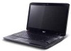
Notebook tour Front View 1 2 15 14 3 4 13 5 12 6 11 10 No. 1 2 3 7 Icon 8 9 Item Acer Crystal Eye webcam Display screen Power button Description Web camera for video communication. Also called Liquid-Crystal Display (LCD), displays computer output (configuration may vary - Acer Aspire 5942G | Service Guide - Page 16
Acer Backup Management for three-step data backup. Enables/disables the Bluetooth function. Indicates the status of Bluetooth communication (only certain models). Enables/disables the wireless LAN function. Indicates the status of wireless LAN communication. Indicates when the hard disk drive - Acer Aspire 5942G | Service Guide - Page 17
the notch and turn the key to secure the lock. Some keyless models are also available. Connects to an AC adapter. Connects to an Ethernet 10/100-based network. Chapter 1 7 - Acer Aspire 5942G | Service Guide - Page 18
HDMI port eSATA port USB 2.0 ports Line-in jack Microphone jack Description Connects to a display device (e.g. external monitor, LCD projector). Supports high definition digital video connections (only for certain models). Connects to eSATA devices. Connect to USB 2.0 devices (e.g. USB mouse, USB - Acer Aspire 5942G | Service Guide - Page 19
to IEEE 1394 devices. Optical drive Internal optical drive; accepts CDs or DVDs. Optical disk access Lights up when the optical drive is active. indicator Optical drive eject Ejects the optical disk from the drive. button Emergency eject hole Ejects the optical drive tray when the computer is - Acer Aspire 5942G | Service Guide - Page 20
's hard disk (secured with screws). Houses the computer's main memory. Locks the battery in position. Enable the computer to stay cool, even after prolonged use. Note: Do not cover or obstruct the opening of the fan. Houses the computer's battery pack. Releases the battery for removal. 10 Chapter - Acer Aspire 5942G | Service Guide - Page 21
is the same as clicking the left button. • Use Acer Bio-Protection fingerprint reader (3) supporting Acer FingerNav 4-way control function (only for certain models) or the it - and your fingers - dry and clean. The TouchPad is sensitive to finger movement; hence, the lighter the touch, the - Acer Aspire 5942G | Service Guide - Page 22
has full-sized keys and an embedded numeric keypad, separate cursor, lock, Windows, function and special keys. Lock Keys and embedded numeric keypad The keyboard has three lock keys which you can toggle on and off. Lock key Caps Lock Num Lock + Scroll Lock + Description - Acer Aspire 5942G | Service Guide - Page 23
Keys The keyboard has two keys that perform Windows-specific functions. Key Description Windows key Pressed alone, this key has the same effect as clicking on the Windows Start button; it launches the Start menu. It can also be used with other keys to provide a variety of functions: < >: Open - Acer Aspire 5942G | Service Guide - Page 24
the computer's controls like screen brightness, volume output and the BIOS utility. To activate hot keys, press and hold the < Bluetooth function*. + + + + + + < > + < > + < > Sleep Display toggle Screen blank Speaker toggle Keyboard - Acer Aspire 5942G | Service Guide - Page 25
and then press the key at the upper-center of the keyboard. NOTE: Note: Some fonts and software do not support the Euro symbol. Please refer to www.microsoft.com/ typography/faq/ key at the upper-center of the keyboard. NOTE: This function varies by the operating system version. Chapter 1 15 - Acer Aspire 5942G | Service Guide - Page 26
Processor Specifications Processor Ci330M CPU Speed 2.13 GH Cores 2 Ci3350M 2.26 GH 2 Ci5430M 2.26 W 35 W 35 W 35 W 35 W 45 W 45 W Acer P/N KC.33 001.D MP KC.35 001.D MP KC.43 001 CPU Fan True Value Table CPU Temperature 50 60 70 80 85 Fan Speed (rpm) 2800 3100 3400 3800 4200 SPL Spec (dBA - Acer Aspire 5942G | Service Guide - Page 27
Off: 86°C • OS shut down at 100°C; H/W shut down at 92°C BIOS Item BIOS vendor InsydeH20 Specification BIOS Version BIOS ROM type BIOS ROM size Features V1.0 Flash 2MB • Support ISIPP • Support Acer UI • Support multi-boot • Suspend to RAM (S3)/Disk (S4) • Various hot-keys for system control - Acer Aspire 5942G | Service Guide - Page 28
On above table, the configuration of slot 1 and slot 2 could be reversed. LAN Interface Item LAN Chipset Supports LAN protocol Specification Broadcom BCM57780A1KMLG for Giga LAN 10/100/1000 Mbps LAN connector type LAN connector location RJ45 Left side Wireless Module 802.3 Item Specification - Acer Aspire 5942G | Service Guide - Page 29
transceiver Automatic MDI crossover function PCIe V1.1 compliant 10/100/10000BASE-T full -duplex/half -duplex MAC Receive side scaling(RSS) for multicore processors Complies with IEEE 802.3, 802.3u, 802.3ab, and 802.1p Wake on LAN (WOL) support meeting the ACPI requirements Statistics for SNMP MIB - Acer Aspire 5942G | Service Guide - Page 30
500 Bytes per sector 512 Data heads 2, 3, 4 Drive Format Disks 1, 2, 2 Spindle speed (RPM) Performance Specifications Buffer size Interface Internal transfer rate (Mbits/sec, max) 1175 I/O data transfer rate 300 (Mbytes/sec max) DC Power Requirements Voltage tolerance 5V ±5% 250 - Acer Aspire 5942G | Service Guide - Page 31
max. 8 MB SATA BD-RE, BD-R, BD-ROM, DVD-ROM, DVD-Video, DVD-RAM DVD-R, DVD-RW, +R, +RW, CD-R, CD-RW CD-DA, CD-ROM (Mode1, Mode2 Form1), CD-ROM XA (Mode2 Form2), Photo CD (Single & Multi session), Video CD, CD-Text, CD-Extra Drawer type manual Sustained: 3.5 Sustained: 10 2 MB SATA CD- - Acer Aspire 5942G | Service Guide - Page 32
Drive Module Item Vendor & model name Performance Specification Transfer rate Buffer Memory Interface Applicable disc formats Specification HLDS GT20N LF, Toshiba TS-L633B LF, Sony AD-7580S LF, PLDS DS-8A3S LF With CD Diskette With DVD Diskette Sustained: 3,600 kB/s (24x) max type manual load - Acer Aspire 5942G | Service Guide - Page 33
Codec Keyboard Card Reader Keyboard Item Keyboard controller Total number of keypads Windows logo key Internal & external keyboard work simultaneously Controller • Realtek ALC669-X for High Definition Audio Codec with Dolby Digital Live • ENE KB926 for Keyboard Controller, Battery management Unit - Acer Aspire 5942G | Service Guide - Page 34
24 Chapter 1 - Acer Aspire 5942G | Service Guide - Page 35
problems, you may need to run Setup. Please also refer to Chapter 4 Troubleshooting when problem arises. To activate the BIOS Utility BIOS SETUP Utility. Navigating the BIOS Utility There are six menu options: Information, Main, Advanced, Security, Boot, and Exit. Follow these instructions - Acer Aspire 5942G | Service Guide - Page 36
BIOS Version: Serial Number: Asset Tag Number: Product Name: Manufacturer Name: UUID: Intel(R) Core(TM)4 Duo CPU Ci7820QM 1.73GHz ST9500325AS 3LF005DB MATSHITADVD V1.00 ATI V008.050I.0-26.00 xxxxxxxxxxxxxxxxxxxx (Max: 22 Byte) xxxxxxxxxxxxxxxxxxxx (Max: 32 Byte) xxxxxxxxxxxxxxxx (Max: 16 Byte) Acer - Acer Aspire 5942G | Service Guide - Page 37
Memory: Video Memory: Quick Boot Network Boot F12 Boot Menu D2D Recovery SATA Mode [19:10:59] [01/09/2009] 4095 MB 512 MB [Enabled] [Enabled] [Disabled] [ function allows the user to create a hidden partition on hard disc drive to store operation system and restore the system to factory defaults - Acer Aspire 5942G | Service Guide - Page 38
Password Set User Password Set HDD Password Power on password Description Shows the setting of the Supervisor password Shows the setting of the user password. Shows the setting of the hard disk password. Press Enter to set the supervisor password. When set, this password protects the BIOS - Acer Aspire 5942G | Service Guide - Page 39
If desired, you can opt to enable the Password on boot parameter. 5. When you are done, press F10 to save the changes and exit the BIOS Setup Utility. Removing a Password Follow these steps: 1. Use the ↑ and ↓ keys to highlight the Set Supervisor Password parameter and press the Enter key. The Set - Acer Aspire 5942G | Service Guide - Page 40
on boot parameter. 6. When you are done, press F10 to save the changes and exit the BIOS Setup Utility. If the verification is OK, the screen will display as following. Setup Notice Changes have been saved. [Continue] The password setting is complete after the user presses Enter. If the current - Acer Aspire 5942G | Service Guide - Page 41
user to decide the order of boot devices to load the operating system. Bootable devices includes the USB diskette drives, the onboard hard disk drive and the DVD drive in the module bay. InsydeH20 Setup Utility Information Main Advanced Security Power Boot Exit Rev. 3.0 Boot priority order: Item - Acer Aspire 5942G | Service Guide - Page 42
to save or discard any changes you made and quit the BIOS Utility. InsydeH20 Setup Utility Information Main Advanced Security Power Boot Changes Save Changes Item Specific Help Exit System Setup and save your changes to CMOS. F1 Help ESC Exit Select Item F5/F6 Change Values F9 Setup Default - Acer Aspire 5942G | Service Guide - Page 43
becomes corrupted. Use the Phlash utility to update the system BIOS flash ROM. NOTE: If you do not have a crisis recovery diskette at hand, then you should create a Crisis Recovery Diskette before you use the Phlash utility. NOTE: Do not install memory-related drivers (XMS, EMS, DPMI) when you use - Acer Aspire 5942G | Service Guide - Page 44
F5/F6 Change Values F9 Setup Default Select Menu Enter Select SubMenu F10 Save and Exit 3. Execute the FLASH.BAT batch file to update BIOS. 4. In flash BIOS, the message Please do not remove AC Power Source displays. If the AC power is not connected, the following warning displays: 32 Chapter - Acer Aspire 5942G | Service Guide - Page 45
Chapter 2 33 - Acer Aspire 5942G | Service Guide - Page 46
WinFlash Utility Perform the following steps to use the WinFlash Utility: 1. Double-click the WinFlash executable. 2. Click OK to begin the update. A progress screen displays. 3. When the process is complete, close all programs and applications and reboot the system. 34 Chapter 2 - Acer Aspire 5942G | Service Guide - Page 47
provide you with removing HDD/BIOS password method: Remove HDD Password: If you key in the wrong HDD password three times, an error is generated. To reset the HDD password, perform the following steps: 1. After the error is displayed, select the Enter Unlock Password option on the screen. 2. An - Acer Aspire 5942G | Service Guide - Page 48
: To clear the User or Supervisor passwords, open the RAM door and use a metal instrument to short the J4 / J5 jumper as shown below. J4 J5 Cleaning BIOS Passwords To clean the User or Supervisor passwords, perform the following steps: 1. From a DOS prompt, execute clnpwd.exe 2. Press 1 or - Acer Aspire 5942G | Service Guide - Page 49
Using Boot Sequence Selector The Boot Sequence Selector allows the boot order to be changed without accessing the BIOS. To use Boot Sequence Selector, perform the following steps: 1. Enter into DOS. 2. Execute BS.exe to display the usage screen. 3. Select the desired boot sequence - Acer Aspire 5942G | Service Guide - Page 50
management. When the BIOS displays Verifying DMI pool data it is checking the table correlates with the hardware before sending to the operating system (Windows, etc.). To update Write Product Name to EEPROM Input: dmitools /wp Acer Write Serial Number to EEPROM Input: dmitools /ws - Acer Aspire 5942G | Service Guide - Page 51
Using the ICW50/ICY70 LAN MAC Utility You can use the MAC.BAT utility to write the MAC.CFG file to the EEPROM under DOS mode. 1. Use a text editor (for example: Notepad) to open the MAC.CFG file. You can see the MAC.CFG contents as below: WriteData = '001122334455' StartAddr=7A WriteLeng=6 KeepByte - Acer Aspire 5942G | Service Guide - Page 52
40 Chapter 2 - Acer Aspire 5942G | Service Guide - Page 53
procedures on how to disassemble the notebook computer for maintenance and troubleshooting. Disassembly Requirements To disassemble the computer, you however, a plastic screwdriver is advised when disassembling parts near or around the motherboard and to prevent scratching of the computer surface - Acer Aspire 5942G | Service Guide - Page 54
Instructions Before proceeding with the disassembly procedure, make sure that you do the following: 1. Turn off the power to the system and all peripherals. 2. Unplug the AC adapter and all power and signal cables from the system. 3. Place the system on a flat, stable surface. 4. Remove the battery - Acer Aspire 5942G | Service Guide - Page 55
gives you a graphic representation on the entire disassembly sequence and instructs you on the components that need to be removed during servicing. For example, if you want to remove the main board, you must first remove the keyboard, then disassemble the inside assembly frame in that order. Turn - Acer Aspire 5942G | Service Guide - Page 56
Removing the Battery Pack 1. Turn the computer over. 2. Slide the battery lock to the unlocked position. 3. Slide and hold the battery release latch to the release position (1), then lift out the battery pack from the main unit (2). 2 1 44 Chapter 3 - Acer Aspire 5942G | Service Guide - Page 57
Removing the Express Dummy Card 1. Push the Express dummy card all the way in to eject it. 2. Pull the card out from the slot. Chapter 3 45 - Acer Aspire 5942G | Service Guide - Page 58
Removing the SD Dummy Card 1. Push the SD dummy card all the way in to eject it. 2. Pull the card out from the slot. 46 Chapter 3 - Acer Aspire 5942G | Service Guide - Page 59
Removing the Lower Covers 1. See "Removing the Battery Pack" on page 44. 2. Loosen the four captive screws in the Memory/HDD and WLAN covers. WLAN Cover 3. Carefully open the Memory/HDD cover. Memory/ HDD Cover 4. Carefully open the WLAN cover. Chapter 3 47 - Acer Aspire 5942G | Service Guide - Page 60
Removing the Optical Drive Module 1. See "Removing the Lower Covers" on page 47. 2. Remove the single screw securing the ODD module. Step ODD Module Size M2.5*5 Quantity 1 Screw Type 3. - Acer Aspire 5942G | Service Guide - Page 61
5. Remove the two screws securing the ODD Bracket and remove the ODD bracket from the module. Step ODD Bracket Size M2*3 Quantity 2 6. Insert a pin in the eject hole of the ODD to eject the ODD tray. Screw Type 7. Press down on the locking catch to release the ODD cover and remove. Chapter 3 - Acer Aspire 5942G | Service Guide - Page 62
1. See "Removing the Lower Covers" on page 47. 2. Use the pull-tab to lift the HDD and disconnect the interface. 3. Lift the hard disk drive module out of the bay. NOTE: To prevent damage to device, avoid pressing down on it or placing heavy objects on top of it. 4. Remove - Acer Aspire 5942G | Service Guide - Page 63
5. Remove the four screws (two each side) securing the hard disk to the carrier. Step HDD Carrier Size M3*3 6. Remove the HDD from the carrier. Quantity 4 Screw Type Chapter 3 51 - Acer Aspire 5942G | Service Guide - Page 64
Removing the DIMM Modules 1. See "Removing the Lower Covers" on page 47. 2. Push out the release latches on both sides of the DIMM socket to release the DIMM module. 3. Remove the DIMM module. 4. Repeat steps for the second DIMM module if present. 52 Chapter 3 - Acer Aspire 5942G | Service Guide - Page 65
Removing the WLAN Module IMPORTANT: If the model purchased supports TV Tuner functionality, remove the TV Tuner Module before removing the WLAN Module. 1. See "Removing the Lower Covers" on page 47. 2. Remove the two screws - Acer Aspire 5942G | Service Guide - Page 66
4. Disconnect the antenna cables from the WLAN Module. IMPORTANT: The black cable attaches to the MAIN terminal and the white cable attaches to the AUX terminal. 5. Detach the WLAN Module from the WLAN socket. NOTE: When reattaching the antennas, ensure the cables are tucked into the chassis to - Acer Aspire 5942G | Service Guide - Page 67
Main Unit Disassembly Process Upper Cover Disassembly Flowchart Remove External Modules before proceeding Rem ove Keyboard Rem ove Upper Cover Lower Cover (see page 54) Upper Cover Rem ove Media Board Rem ove Launch Board Rem ove Speaker Module Rem ove - Acer Aspire 5942G | Service Guide - Page 68
Cover Disassembly Flowchart Remove External Modules before proceeding Rem ove Keyboard Rem ove Upper Cover Rem ove LCD Module Rem ove Bluetooth Module Rem ove Card Reader Board Rem ove Saddle Rem ove Subwoofer Rem ove USB Board Rem ove Hinge Wells Rem ove Mainboard Rem ove RTC Battery Rem - Acer Aspire 5942G | Service Guide - Page 69
Removing the Keyboard 1. Locate the five securing clips on the top edge of the Keyboard. 2. Starting with the central clip, release all five securing clips by pressing down with a suitable plastic tool. 3. Pry up the centre of the Keyboard as shown. Chapter 3 57 - Acer Aspire 5942G | Service Guide - Page 70
4. Rotate the Keyboard upward away from the Upper Cover and place it face down on the TouchPad area. 5. Open the Keyboard backlight FFC connector and disconnect the FFC. 6. Open the Keyboard FFC connector and disconnect the FFC. 7. Remove the Keyboard from the Upper Cover. 58 Chapter 3 - Acer Aspire 5942G | Service Guide - Page 71
Removing the Upper Cover 1. See "Removing the Keyboard" on page 57. 2. Turn the computer over. Remove the twenty-three screws on the bottom panel. Step Upper Cover (red callout) Upper Cover (blue callout) - Acer Aspire 5942G | Service Guide - Page 72
Cover to the Upper Cover, and remove the Keyboard Cover. Step Keyboard Cover Size M2.5*5 Quantity 1 Screw Type 5. Disconnect the following FFCs (A, B, D, and E) and cables (C, F, and G) from the Mainboard. G F B E A C D NOTE: Avoid pulling on cables directly to prevent - Acer Aspire 5942G | Service Guide - Page 73
6. Starting on the front left side of the casing and working along toward the right, pry the upper and lower covers apart as shown. 7. Work along the casing on the right and left sides toward the back edge, prying apart the casing. 8. Remove the Upper Cover as shown. Chapter 3 61 - Acer Aspire 5942G | Service Guide - Page 74
Removing the Media Board 1. See "Removing the Upper Cover" on page 59. 2. Turn the Upper Cover over and lift the Media Board FFC to disconnect the adhesive. 3. Turn the Upper Cover over. Lift the Media Board cover, left side first, and remove the cover from the Upper Cover. 4. Press down the - Acer Aspire 5942G | Service Guide - Page 75
5. Lift the Media Board away from the Upper Cover (1) and feed the FFC through the Upper Cover (2) to remove the Media Board. 1 2 Chapter 3 63 - Acer Aspire 5942G | Service Guide - Page 76
Removing the Launch Board 1. See "Removing the Upper Cover" on page 59. 2. Turn the Upper Cover over and lift the Launch Board FFC to disconnect the adhesive. 3. Turn the Upper Cover over. Lift the Launch Board cover, left side first, and remove the cover from the Upper Cover. 4. Press down the - Acer Aspire 5942G | Service Guide - Page 77
5. Lift the Launch Board away from the Upper Cover. 6. Feed the FFC through the Upper Cover to remove the Launch Board Chapter 3 65 - Acer Aspire 5942G | Service Guide - Page 78
Removing the Speaker Module 1. See "Removing the Upper Cover" on page 59. 2. Lift the mylar covering to expose the Speaker cable as shown. 3. Remove the Speaker cable from the cable channel as shown. 4. Remove the four securing screws from the Speaker module. Step Speaker Module Size M2.5*3 - Acer Aspire 5942G | Service Guide - Page 79
5. Using both hands, lift the Speaker Module upward to remove it from the Upper Cover. Chapter 3 67 - Acer Aspire 5942G | Service Guide - Page 80
Removing the Power Saving Board 1. See "Removing the Speaker Module" on page 66. 2. Remove the Power Saving Board cable from the cable channel as shown. 3. Remove the two securing screws from the board. Step Power Saving Board Size M2.5*3 4. Remove the board from the chassis. Quantity 2 Screw - Acer Aspire 5942G | Service Guide - Page 81
5. Disconnect the cable from the Power Saving Board as shown. Chapter 3 69 - Acer Aspire 5942G | Service Guide - Page 82
Removing the Volume Control Board 1. See "Removing the Upper Cover" on page 59. 2. Lift the Volume Control Board FFC away from the Upper Cover to detach the adhesive. 3. Remove the two screws securing the board to the Upper Cover. Step Volume Control Board Size M2.5*3 4. Lift the board clear of - Acer Aspire 5942G | Service Guide - Page 83
Removing the MIC Board 1. See "Removing the Upper Cover" on page 59. 2. Remove the adhesive tape securing the MIC cable to the Upper Cover. 3. Remove the MIC cable from the cable channel as shown. Ensure that the cable is free from all cable clips. 4. Lift the MIC Board clear of the Upper Cover as - Acer Aspire 5942G | Service Guide - Page 84
Removing the Button Board and Finger Print Reader 1. See "Removing the Upper Cover" on page 59. 2. Lift the Button Board FFC to detach the adhesive holding it in place. 3. Remove the two screws securing the Button Board and Finger Print Reader to the Upper Cover. Step Button Board Size M2.5*5 - Acer Aspire 5942G | Service Guide - Page 85
5. Open the FFC locking latch and disconnect the Finger Print Reader FFC from the Button Board. 6. Remove Button Board from the bracket. 7. Turn the bracket over and remove the two screws securing the Finger Print Reader to the bracket. Step Finger Print Reader Size M2*3 Quantity 2 Screw Type - Acer Aspire 5942G | Service Guide - Page 86
8. Remove the Finger Print Reader from the bracket as shown. 74 Chapter 3 - Acer Aspire 5942G | Service Guide - Page 87
Removing the TouchPad Bracket IMPORTANT: The TouchPad cannot removed from the Upper Cover. Replace the entire Upper Cover if the TouchPad malfunctions. 1. See "Removing the Button Board and Finger Print Reader" on page 72. 2. Lift the TouchPad FFC to detach the adhesive securing it in place. 3. Open - Acer Aspire 5942G | Service Guide - Page 88
5. Remove the two screws securing the TouchPad Bracket in place. Step TouchPad Bracket Size M2.5*3 Quantity 2 Screw Type 6. Lift the TouchPad Bracket, front edge first, and remove it from the Upper Cover. 76 Chapter 3 - Acer Aspire 5942G | Service Guide - Page 89
Removing the LCD Module IMPORTANT: The LCD Module cannot be disassembled outside of factory conditions. If any part of the LCD Module is faulty, such as the camera, antenna or LCD panel, the whole module must - Acer Aspire 5942G | Service Guide - Page 90
5. Remove the USB Board cable from the cable clips as shown. 6. Remove the adhesive tapes securing the USB Board and Backlight cables in place. 7. Disconnect the Backlight and USB Board cables from the Mainboard. 78 Chapter 3 - Acer Aspire 5942G | Service Guide - Page 91
8. Lift the USB Board cable to detach the adhesive securing it in place. 9. Remove the USB Board and Backlight cables from the cable channel. Ensure that the cables are free from all cable clips. 10. Remove the Antenna and Backlight cables from the cable clip as shown. Chapter 3 79 - Acer Aspire 5942G | Service Guide - Page 92
11. Pass the Antenna and Backlight cables through the space between the Battery Bay and Hinge well as shown. 12. Remove the cables from the final cable clip as shown. 13. Disconnect the Conductive cable from the Mainboard. 80 Chapter 3 - Acer Aspire 5942G | Service Guide - Page 93
14. Disconnect the LVDS cable from the Mainboard. 15. Remove the Conductive and LVDS cables from the cable channel. Ensure that the cables are free from all cable clips. 16. Remove the four screws ( - Acer Aspire 5942G | Service Guide - Page 94
17. Using both hands, lift the LCD Module clear of the Lower Cover. IMPORTANT: The LCD Module cannot be disassembled outside of factory conditions. If any part of the LCD Module is faulty, such as the camera, antenna or LCD panel, the whole module must be replaced. 82 Chapter 3 - Acer Aspire 5942G | Service Guide - Page 95
Removing the Saddles 1. See "Removing the Upper Cover" on page 59. 2. Lift the left side Saddle clear of the Lower Cover as shown. 3. Remove the two screw securing the right side Saddle to the Lower Cover. Step Right Saddle Size M2.5*5 Quantity 2 Screw Type Chapter 3 83 - Acer Aspire 5942G | Service Guide - Page 96
4. Lift the right side Saddle clear of the Lower Cover as shown. 84 Chapter 3 - Acer Aspire 5942G | Service Guide - Page 97
Removing the USB Board 1. See "Removing the Saddles" on page 83. 2. Remove the single screw securing the USB Board to the Lower Cover. Step USB Board Size M2.5*3 Quantity 1 3. Remove the USB Board from the Lower Cover as shown. Screw Type Chapter 3 85 - Acer Aspire 5942G | Service Guide - Page 98
Removing the Subwoofer 1. See "Removing the LCD Module" on page 77. 2. Disconnect the Subwoofer cable from the Mainboard. 3. Remove the cable from the channel. Ensure that the cable is free from all cable clips. 4. Using both hands, lift the Subwoofer clear of the Lower Cover. 86 Chapter 3 - Acer Aspire 5942G | Service Guide - Page 99
Removing the Bluetooth Module 1. See "Removing the Upper Cover" on page 59. 2. Disconnect the Bluetooth cable from the Mainboard. 3. Remove the cable from the cable channel as shown. 4. Lift the module clear of the chassis. Chapter 3 87 - Acer Aspire 5942G | Service Guide - Page 100
5. Disconnect the cable from the Bluetooth Module. 88 Chapter 3 - Acer Aspire 5942G | Service Guide - Page 101
Removing the Card Reader Board 1. See "Removing the Saddles" on page 83. 2. Remove the four screws securing the Card Reader Board to the Lower Cover. Step Card Reader Board Size M2.5*3 Quantity 4 Screw Type 3. Lift the left side of the board to disconnect the reader interface from the Mainboard - Acer Aspire 5942G | Service Guide - Page 102
Removing the Hinge Wells 1. See "Removing the Subwoofer" on page 86. 2. Remove the two screws (one each side) securing the Hinge Wells to the Lower Cover. Step Hinge Wells Size M2.5*3 Quantity 2 3. Lift the Hinge Wells clear of the Lower Cover. Screw Type 90 Chapter 3 - Acer Aspire 5942G | Service Guide - Page 103
Cover. Step Mainboard Size M2.5*3 Quantity 1 Screw Type 3. Pivot the Mainboard upward and remove it from the chassis, right side first. Place the Mainboard on a clean, dust-free surface. Chapter 3 91 - Acer Aspire 5942G | Service Guide - Page 104
Removing the RTC Battery IMPORTANT: Follow local regulations for disposal of all batteries. 1. See "Removing the Mainboard" on page 91. 2. The RTC Battery is soldered to the Mainboard. To replace the battery, solder the new battery to the connections shown. 92 Chapter 3 - Acer Aspire 5942G | Service Guide - Page 105
Removing the VGA/MXM Card NOTE: The following procedure outlines the removal steps for models supporting VGA Cards. The procedure for MXM Cards requires the removal of two screws, though the remaining steps are identical. 1. See "Removing the Mainboard" on page - Acer Aspire 5942G | Service Guide - Page 106
Removing the Thermal Module 1. See "Removing the Mainboard" on page 91. 2. Disconnect the fan cable from the Mainboard. 3. Remove the single screw securing the Fan to the Mainboard (green callout). 4. Remove the four securing screws (in reverse numerical order from screw 4 to screw 1) from the - Acer Aspire 5942G | Service Guide - Page 107
5. Using both hands, lift the Thermal Module clear of the Mainboard. Chapter 3 95 - Acer Aspire 5942G | Service Guide - Page 108
shown. IMPORTANT: The pins on the underside of the CPU are very delicate. If they are damaged, the CPU may malfunction. Place the CPU on a clean, dry surface when it is not installed. 96 Chapter 3 - Acer Aspire 5942G | Service Guide - Page 109
Main Module Reassembly Procedure Replacing the CPU IMPORTANT: The CPU has a Pin1 locator that must be positioned corresponding to the marker on the CPU socket. 1. Carefully turn the mainboard upside down (CPU side up), and place the CPU into the CPU socket as shown, taking note of the Pin1 locator. - Acer Aspire 5942G | Service Guide - Page 110
centre of the CPU-there is no need to spread the grease manually, the force used during the installation of the Thermal Module is as level as possible to spread the thermal grease evenly. 4. Replace the single Fan screw and the four Thermal Module screws (in numerical order from screw 1 to - Acer Aspire 5942G | Service Guide - Page 111
Replacing the VGA/MXM Card NOTE: The following procedure outlines the installation steps for models supporting VGA Cards. The procedure for MXM Cards requires two screws, though the remaining steps are identical. 1. Insert the card in to the Mainboard connector as - Acer Aspire 5942G | Service Guide - Page 112
Replacing the Mainboard 1. Insert the Mainboard in to the Lower Cover, left side first. Ensure that the I/O ports on the left side of the Mainboard are located correctly through the Lower Case. 2. Pivot the Mainboard in to the Lower Cover as shown. 3. Replace the single screw securing the - Acer Aspire 5942G | Service Guide - Page 113
Replacing the Hinge Wells 1. Replace the left and right Hinge Wells in the Lower Cover as shown. Ensure that the Wells are seated correctly on the locating pins. 2. Replace the two screws to secure the Hinge Wells in the Lower Cover. Replacing the Card Reader Board 1. Insert the Card Reader Board - Acer Aspire 5942G | Service Guide - Page 114
3. Replace the four screws to secure the Card Reader Board to the Lower Cover. Replacing the Bluetooth Module 1. Connect the Bluetooth cable to the module as shown. 2. Place the module in the Lower Cover. Ensure that the module is seated correctly on the locating pins. 3. Run - Acer Aspire 5942G | Service Guide - Page 115
Replacing the Subwoofer 1. Place the module in the Lower Cover. Ensure that 2. Run the cable along the cable channel using all the module is seated correctly on the locating pins. available clips. 3. Connect the Subwoofer cable to the Mainboard as shown. Replacing the USB Board 1. Place the board - Acer Aspire 5942G | Service Guide - Page 116
Replacing the Saddles 1. Align the screw holes and locating pins on the Saddles and the Lower Cover and replace the Saddles. 2. Replace the two screws to secure the Right Saddle to the Lower Cover. NOTE: The Left Saddle is not secured with screws. 104 Chapter 3 - Acer Aspire 5942G | Service Guide - Page 117
Replacing the LCD Module IMPORTANT: The LCD Module cannot be disassembled outside of factory conditions. If any part of the LCD Module is faulty, such as the camera, antenna or LCD panel, the whole module must - Acer Aspire 5942G | Service Guide - Page 118
3. Run the Conductive cable along the cable channel 4. Run the LVDS cable along the cable channel using using all the cable clips. all the cable clips. 5. Connect the LVDS cable to the Mainboard as shown. 6. Connect the Conductive cable to the Mainboard as shown. Replacing the TouchPad Bracket - Acer Aspire 5942G | Service Guide - Page 119
2. Insert the two screws to secure the TouchPad Bracket in place. Step TouchPad Bracket Size M2.5*3 Quantity 2 Screw Type 3. Adhere the Finger Print Reader protection strip to the TouchPad Bracket as shown. 4. Connect the TouchPad FFC to the TouchPad and close the locking latch. Chapter 3 - Acer Aspire 5942G | Service Guide - Page 120
5. Adhere the TouchPad FFC to the touchpad bracket as shown. Replacing the Button Board and Finger Print Reader 1. Place the Finger Print Reader into the bracket as shown. 2. Insert the two screws to secure the Finger Print Reader to the bracket. Step Finger Print Reader Size M2*3 Quantity 2 - Acer Aspire 5942G | Service Guide - Page 121
3. Place the Button Board into the bracket. 4. Connect the Finger Print Reader FFC to the Button Board and close the FFC locking latch. 5. Place the button board assembly into the Upper Cover, taking care to align the screw holes. Chapter 3 109 - Acer Aspire 5942G | Service Guide - Page 122
6. Replace the two screws to secure the Button Board and Finger Print Reader to the Upper Cover. Step Button Board Size M2.5*5 Quantity 2 7. Adhere the Button Board FFC to the back of the touchpad. Screw Type 110 Chapter 3 - Acer Aspire 5942G | Service Guide - Page 123
Replacing the MIC Board 1. Place the MIC Board into the Upper Cover as shown. 2. Insert the MIC cable from the cable channel as shown. Ensure that the cable is secured by all cable clips. 3. Adhere the adhesive tape to secure the MIC cable to the Upper Cover. Chapter 3 111 - Acer Aspire 5942G | Service Guide - Page 124
Replacing the Volume Control Board 1. Place the board into the Upper Cover. 2. Insert the two screws to secure the board to the Upper Cover. Step Volume Control Board Size M2.5*3 Quantity 2 3. Adhere Volume Control Board FFC to the Upper Cover as shown. Screw Type 112 Chapter 3 - Acer Aspire 5942G | Service Guide - Page 125
Replacing the Power Saving Board 1. Connect the cable to the Power Saving Board as shown. 2. Place the board into the chassis. 3. Insert the two securing screws into the board. Step Power Saving Board Size M2.5*3 Quantity 2 Screw Type Chapter 3 113 - Acer Aspire 5942G | Service Guide - Page 126
4. insert the Power Saving Board cable into the cable channel as shown. 114 Chapter 3 - Acer Aspire 5942G | Service Guide - Page 127
Replacing the Speaker Module 1. Using both hands, place the Speaker Module into the Upper Cover. 2. Insert the four screws to secure the Speaker module to the Upper Cover. Step Speaker Module Size M2.5*3 Quantity 4 3. Insert the Speaker cable into the cable channel as shown. Screw Type - Acer Aspire 5942G | Service Guide - Page 128
4. Replace the mylar covering to cover the Speaker cable as shown. 116 Chapter 3 - Acer Aspire 5942G | Service Guide - Page 129
Replacing the Launch Board 1. Feed the FFC through the penetration in the Upper Cover as shown. 2. Place the Launch Board into the Upper Cover. 3. Press down on the top of the board to engage the securing clips (1) and push the Launch Board in the direction of the arrow (2) to lock the board in - Acer Aspire 5942G | Service Guide - Page 130
4. Turn the Upper Cover over and insert the Launch Board cover into the Upper Cover. 5. Turn the Upper Cover over and adhere the Launch Board FFC to the upper cover. 118 Chapter 3 - Acer Aspire 5942G | Service Guide - Page 131
Replacing the Media Board 1. Insert the FFC into the penetration in the Upper Cover (1) and place the Media Board into the Upper Cover (2) as shown. 2 1 2. Press down on the board so the securing clips engage and push the Media Board in the direction of the arrow (2). 1 Securing Clip 2 3. Turn the - Acer Aspire 5942G | Service Guide - Page 132
4. Turn the Upper Cover over and adhere the Media Board FFC to the upper cover. Replacing the Upper Cover 1. Insert the Upper Cover into the assembly back edge first as shown. 2. Work along the casing on the right and left sides toward the front edge, pressing the casing together. A click indicates - Acer Aspire 5942G | Service Guide - Page 133
3. Starting on the front left side of the casing and working along toward the right, press the upper and lower covers together as shown. A click indicates the securing clips have engaged. 4. Connect the following FFCs (A, B, D, and E) and cables (C, F, and G) to the Mainboard. G F B E A C D - Acer Aspire 5942G | Service Guide - Page 134
5. Replace the Keyboard Cover and insert the single screw securing the Keyboard Cover to the Upper Cover. Step Keyboard Cover Size M2.5*5 Quantity 1 Screw Type 6. Turn the computer over. Connect the Launch Board FFC connector and lock the FFC connector. 122 Chapter 3 - Acer Aspire 5942G | Service Guide - Page 135
7. Turn the computer over. Insert the twenty-three screws on the bottom panel. Step Upper Cover (red callout) Upper Cover (blue callout) Upper Cover (green callout) Size M2.5*8 M2.5*5 M2.5*3 Quantity 18 2 3 Screw Type Chapter 3 123 - Acer Aspire 5942G | Service Guide - Page 136
Replacing the Keyboard 8. Insert the Keyboard backlight FFC and lock the connector. 9. Connect the Keyboard FFC and lock the connector. 10. Slide the keyboard away from the LCD screen to engage the securing tabs on the keyboard. 124 Chapter 3 - Acer Aspire 5942G | Service Guide - Page 137
11. Press down around the edges of the Keyboard to secure it in place. Replacing the WLAN Module 1. Insert the WLAN Module into the mini-card socket. 2. Connect the antenna cables to the WLAN - Acer Aspire 5942G | Service Guide - Page 138
3. Replace the Mini-Card Bracket as shown. 4. Insert the two screws to secure the Mini-Card Bracket and WLAN Module to the Mainboard Step WLAN Module Size M2*3 Quantity 2 Screw Type 126 Chapter 3 - Acer Aspire 5942G | Service Guide - Page 139
Replacing the DIMM Modules 1. Insert the DIMM Module in place. 2. Press down to lock the DIMM module in place. Replacing the Hard Disk Drive Module 1. Place the HDD in the HDD carrier. 2. Replace the four screws (two each side) to secure the carrier. 3. Insert the HDD SATA interface connector - Acer Aspire 5942G | Service Guide - Page 140
Replacing the ODD Module 1. With the ODD tray in the eject position, replace the 2. Secure ODD bracket with two screws. ODD bezel on the new ODD Module. 3. Slide the module in to the chassis and press until 4. Replace the single screw to secure the Module. the module is flush with the chassis. 128 - Acer Aspire 5942G | Service Guide - Page 141
Replacing the Lower Covers 1. Replace the Memory Cover back edge first as shown. 2. Replace the memory/HDD cover back edge first as shown. IMPORTANT: Ensure that the all the securing tabs are correctly located in the casing. 3. Secure the four captive screws. WLAN Cover HDD Cover Replacing the - Acer Aspire 5942G | Service Guide - Page 142
Dummy into the slot until an audible click indicates that the card is correctly inserted. Replacing the Battery 1. Slide and hold the battery release latch to the release position (1), insert the battery pack and press down (2). 2 2. Slide the battery lock in the direction shown to secure the - Acer Aspire 5942G | Service Guide - Page 143
Troubleshooting Chapter 4 Common Problems Use the following procedure as a guide for computer problems. NOTE: The diagnostic tests are intended to test only Acer products. Non-Acer Failure Page 135 Internal Keyboard Failure Page 135 TouchPad Support Information" on page 231. Chapter 4 131 - Acer Aspire 5942G | Service Guide - Page 144
the following actions one at a time to correct the problem. 1. Check the power cable is properly connected to Thermal Unit (see "Thermal Unit Failure" on page 144) and fan airways are free of obstructions. 5. Remove all external and non-essential Support Information" on page 231. 132 Chapter 4 - Acer Aspire 5942G | Service Guide - Page 145
at least one of the following occurs: • Fans start up • Status LEDs light up If there is no power, see "Power On Issue" on page 132. 3. Drain any stored power by removing the power cable and battery and holding down the power button for 10 seconds. Reconnect the power and reboot the computer - Acer Aspire 5942G | Service Guide - Page 146
, see "Online Support Information" on page 231. Random Loss of BIOS Settings If the computer is experiencing intermittent loss of BIOS information, perform the following actions one at a time to correct the problem. 1. If the computer is more than one year old, replace the CMOS battery. 2. Run - Acer Aspire 5942G | Service Guide - Page 147
If the LCD fails, perform the following actions one at a time to correct the problem. Do not replace a nondefective FRUs: Built-In Keyboard Failure If the built-in Keyboard fails, perform the following actions one at a time to correct the problem. Do not replace a non-defective FRUs: Chapter 4 135 - Acer Aspire 5942G | Service Guide - Page 148
doesn't work, perform the following actions one at a time to correct the problem. Do not replace a non-defective FRUs: Internal Speaker Failure If the internal Speakers fail, perform the following actions one at a time to correct the problem. Do not replace a non-defective FRUs: 136 Chapter 4 - Acer Aspire 5942G | Service Guide - Page 149
Device Manager. Check the Device Manager to determine that: • The device is properly installed. • There are no red Xs or yellow exclamation marks. • There are no device conflicts. • No hardware is listed under Other Devices. 3. Roll back the audio driver to the previous version, if updated recently - Acer Aspire 5942G | Service Guide - Page 150
perform the following actions one at a time to correct the problem. Do not replace a non-defective FRUs: Microphone Problems If internal or external Microphones do no operate correctly, perform test. 8. If the Issue is still not resolved, see "Online Support Information" on page 231. 138 Chapter 4 - Acer Aspire 5942G | Service Guide - Page 151
the onscreen information to resolve the problem. 4. Run the Windows Memory Diagnostic Tool. For more information see Windows Help and Support. 5. Restart the computer and press F2 to enter the BIOS Utility. Check the BIOS settings are correct and that CD/DVD drive is set as the first boot device - Acer Aspire 5942G | Service Guide - Page 152
not play when loaded • Blank discs do not burn correctly • DVD or CD play breaks up or jumps • Optical drive not found or not active: • Not shown in My Computer or the BIOS setup • LED does not flash when the computer starts up • The tray does not eject • Access failure screen displays - Acer Aspire 5942G | Service Guide - Page 153
reaches zero, the region cannot be changed even Windows is reinstalled or the drive is moved to another computer. a. Navigate to Start´ Control Panel´ System and Maintenance´ System´ Device Manager. b. Double-click DVD/CD-ROM drives. c. Right-click DVD drive and click Properties, then click the DVD - Acer Aspire 5942G | Service Guide - Page 154
for the other ATA Devices shown if applicable. Drive Not Detected If Windows cannot detect the drive, perform the following actions one at a time to correct the problem. 1. Restart the computer and press F2 to enter the BIOS Utility. 2. Check that the drive is detected in the ATAPI Model Name field - Acer Aspire 5942G | Service Guide - Page 155
Modem Function Failure If the internal Modem fails, perform the following actions one at a time to correct the problem. Do not replace a non-defective FRUs: START RJ-11 well connected? No Connect it well Modem wire well connected? No Connect it well Modem card - Acer Aspire 5942G | Service Guide - Page 156
to check the events log for errors. For more information see Windows Help and Support. 10. Roll back the mouse driver to the previous version if updated recently. 11. Remove and reinstall the mouse driver. 12. Check the Device Manager to determine that: • The device is properly installed. There are - Acer Aspire 5942G | Service Guide - Page 157
"Online Support Information" on page 231. Other Failures If the CRT Switch, Dock, LAN Port, external MIC or Speakers, PCI Express Card, 5-in-1 Card Reader or Volume Wheel fail, perform the following general steps to correct the problem. Do not replace a non-defective FRUs: 1. Check Drive whether is - Acer Aspire 5942G | Service Guide - Page 158
Verify that all attached devices are supported by the computer. NOTE: Verify Acer devices • Printer, mouse, and other external devices • Battery pack • Hard disk drive • DIMM • CD-ROM/Diskette drive Module • PC Cards 4. Power-on the computer. 5. Determine if the problem has changed. 6. If the problem - Acer Aspire 5942G | Service Guide - Page 159
on and switch to Protected mode Patching CPU microcode Setup Cache as RAM PCIE MMIO Base Address initial CPU Generic MSR initialization Setup CPU speed Cache as RAM test Tune CPU frequency ratio to maximum level Setup BIOS ROM cache Enter Boot Firmware Volume NOTE: The color bar items indicate - Acer Aspire 5942G | Service Guide - Page 160
Initialization Memory Initial for Normal boot. Memory Initial for Crisis Recovery Simple Memory test TXT function early Initialization Start Load Recovery Image completed Start Flash BIOS with Recovery image Loading BIOS image to RAM Loading DXE core Enter DXE core NOTE: The color bar items indicate - Acer Aspire 5942G | Service Guide - Page 161
Multi-processor Middle Initialization SMBUS Driver Initialization 8259 Initialization RTC Initialization SATA Controller early Initialization Setup SMM Control service Setup Legacy Interrupt service Relocate SMM BASE SMI test VTD Initial Legacy BIOS Initialization Legacy interrupt function - Acer Aspire 5942G | Service Guide - Page 162
Post Code 10 11 12 13 14 15 16 service ASF Initialization PCI enumeration PCI resource assign complete PCI enumeration complete Keyboard Controller, Keyboard ISA BUS driver initialization Enter Boot manager Try to boot system to OS Shadow Misc. Option ROM Save S3 resume required data in RAM Last - Acer Aspire 5942G | Service Guide - Page 163
SMM SMM SMM SMM SMM SMM SMM SMM Post Code 0xA0 0xA2 0xA6 0xA7 0xA1 0xA3 0xA4 0xA5 Description Identify Flash device in SMM SMM service initial OS call ACPI enable function ACPI enable function complete Enter S1 Enter S3 Enter S4 Enter S5 Chapter 4 151 - Acer Aspire 5942G | Service Guide - Page 164
Functionality Name (Include\ PostCode.h) SMM_ACPI_DISABLE_START SMM_ACPI_DISABLE_END Phase SMM SMM Post Code 0xA8 0xA9 Description OS call ACPI disable function ACPI disable function complete InsydeH2ODDT Debugger POST Code Table Functionality Name (Include\ PostCode.h) Used by Insyde debugger - Acer Aspire 5942G | Service Guide - Page 165
21 JBT1 11 LED 9, LED 10, 11, 12, 13 22 SW2 Description Subwoofer (2P) TV Tuner Board to MB (8P) (Cable) Speaker Conn. (4P) Media Console (R) to MB (16P) (FCC) Mic. Conn. (4P) (Cable) K/B Conn. (26P) LED Card Reader Board to MB (60P) Standoff Board to Board Bluetooth Conn. Switch Chapter 5 153 - Acer Aspire 5942G | Service Guide - Page 166
JSATA2 3 JSATA3 4 5 PJP1 6 JRJ1 7 JCRT1 8 JFAN1 Description Battery Connector H9, 2 DDRIII STD HDD Conn. Standoff Fan DC-IN Conn. (DIS) Blue DC-IN Conn. (UMA) Yellow RJ45 D. Sub Fan Conn. Item 9 JHDMI1 10 JSATA1 11 JUSB1/2 12 JLINE1 13 JMIC1 14 JHP1 15 JCPU1 16 JDIMM1 17 JDIMM2 Description Launch - Acer Aspire 5942G | Service Guide - Page 167
LS-5511P Switch Board Top View Bottom View 1 2 3 4 7 5 6 Item Description 1 LED3 Backup Button 2 SW3 Backup LED 3 LED2 Bluetooth Button 4 SW2 Bluetooth LED 5 LED1 Wireless Button 6 SW1 Wireless LED 7 JP1 To M/B Connector Chapter 5 155 - Acer Aspire 5942G | Service Guide - Page 168
LS-5512P Media Board 1 2 3 Item Description 1 JP3 Power Saving Conn. 2 JP1 Volume Control Conn. 3 JP2 To M/B Conn. 156 Chapter 5 - Acer Aspire 5942G | Service Guide - Page 169
LS-5513P TV-Tuner Board Top View 3 1 Bottom View 2 4 5 Item 1 ANT1 2 JP4 Description TV Tuner Cable Conn. ACER LOGO Back light Conn. Item 3 JP2 4 JP3 5 JP1 Description TV Tuner Conn. USB Conn. To M/B Conn. Chapter 5 157 - Acer Aspire 5942G | Service Guide - Page 170
LS-5514P Card Reader Board 1 2 3 4 56 Item Description 1 J1 1394 Conn. 2 JREAD1 7 in 1 Card Reader 3 IR IR Item 4 JMINI2 5 JMINI1 6 JP1 Description Wireless LAN Conn. TV Tuner Connector To M/B Conn. 158 Chapter 5 - Acer Aspire 5942G | Service Guide - Page 171
LS-5515P Touch Pad Button Board Bottom View 1 2 3 4 Item 1 JP3 2 JP1 Description Finger Print Conn To M/B Connector Top View Item 3 JP2 4 SW1/2 Description TP Module Conn. Left & Right Buttons Chapter 5 159 - Acer Aspire 5942G | Service Guide - Page 172
LS-5516P Power Saving Board Top View Bottom View 1 Item 1 SW1 Description Power Saving Button 2 Item 2 JP1 Description To Media Board Conn. 160 Chapter 5 - Acer Aspire 5942G | Service Guide - Page 173
LS-5517P Volume Board Top View 1 2 Bottom View Item 1 SW1 Description Volume Button Item 2 JP1 Description To Media Board Conn. Chapter 5 161 - Acer Aspire 5942G | Service Guide - Page 174
LS-5518P Color Engine Board 1 2 3 Item 1 SENSE1 2 SENSE2 Description Acer Logo Backlight Color Engine Item 3 JP1 Description To TV-Tuner Board Conn. 162 Chapter 5 - Acer Aspire 5942G | Service Guide - Page 175
for clearing passwords and BIOS recovery for the Aspire 5942 Series. The Aspire 5942 Series provides one Hardware Open Gap on the main board for clearing password check, and one Hotkey for enabling BIOS Recovery. Clearing Password Check Hardware Open Gap Description The J4 and J5 Clear CMOS Jumpers - Acer Aspire 5942G | Service Guide - Page 176
tool from the HW Gap. • Restart system. Press F2 key to enter BIOS Setup menu. • If there is no Password request, BIOS Password is cleared. Otherwise, please follow the steps and try again. NOTE: The steps are only for clearing BIOS Password (Supervisor Password and User Password). 164 Chapter 5 - Acer Aspire 5942G | Service Guide - Page 177
Crisis Disk program in another system with Windows 7 OS. Follow the steps below: 1. Plug in the USB disk. 2. Launch the wincris.exe program to create a USB Crisis Disk. Click Start to initiate the process. 3. Select the Quick Format option to format the disk and click Start. Follow the instructions - Acer Aspire 5942G | Service Guide - Page 178
166 Chapter 5 - Acer Aspire 5942G | Service Guide - Page 179
the FRU (Field Replaceable Unit) listing in global configurations of Aspire 5942 Series. Refer to this chapter whenever ordering for parts to made, it will not be noted on the printed Service Guide. For ACER AUTHORIZED SERVICE PROVIDERS, your Acer office may have a DIFFERENT part number code from - Acer Aspire 5942G | Service Guide - Page 180
Aspire 5942 Series Exploded Diagrams Main Assembly 1 2 3 4 7 5 6 No. Description 1 Keyboard 2 Upper Cover 3 Mainboard 4 Thermal Module 5 Subwoofer 6 Lower Cover 7 Hinge Saddle-L Acer P/N KB.I140A.001 TBD MB.PH802.001 60.PH702.008 23.PH702.003 TBD 33.PH702.002 168 Chapter 6 - Acer Aspire 5942G | Service Guide - Page 181
Base Assembly 1 2 3 No. Description 1 HDD Door 2 Mini Door 3 Lower Cover Acer P/N TBD Confirm 42.PH702.003 42.PH702.004 60.PH702.002 Chapter 6 169 - Acer Aspire 5942G | Service Guide - Page 182
Aspire 5942 Series FRU List CATEGORY BOARD Description Acer Part Number Lan Intel WLAN 512AN_HMWG Shirley Peak 5100 MM#895373 Lan Intel WLAN 512AG_HMWG Shirley Peak 5100 MM#897072 Lan Intel WLAN 533AN_HMWG Shirley Peak MM#895401 KI.SPH01.003 KI.SPH01.005 KI.SPH01.001 Foxconn Bluetooth BRM 2046 - Acer Aspire 5942G | Service Guide - Page 183
CATEGORY CABLE Description BLUE TOOTH CABLE T/P FFC Acer Part Number 50.PH702.001 50.PH702.002 POWER SAVING CABLE USB CABLE RF CABLE ON-OFF BOARD CABLE TV TUNER ANTENNA SMB-PAL JACK - Acer Aspire 5942G | Service Guide - Page 184
CATEGORY HDD DOOR Description MINI DOOR HDD BRACKET Acer Part Number 42.PH702.003 42.PH702.004 33.PH702.003 HDD CONNECTOR MINI CARD BRACKET 20.PH702.001 33.PH702.004 LAUNCH COVER - BT, - Acer Aspire 5942G | Service Guide - Page 185
14 Standard 87KS Black UK Backlit Keyboard ACER AC4B SM50 Internal 14 Standard 87KS Black German Backlit Keyboard ACER AC4B SM50 Internal 14 Standard 87KS Black Swiss/G Backlit Keyboard ACER AC4B SM50 Internal 14 Standard 87KS Black Belgium Backlit Keyboard ACER AC4B SM50 Internal 14 Standard 87KS - Acer Aspire 5942G | Service Guide - Page 186
Black CZ/SK Backlit Keyboard ACER AC4B SM50 Internal 14 Standard 91KS Black Japanese Backlit Acer Part Number KB.I140A.033 KB.I140A.009 KB.I140A.010 KB.I140A.019 ODD SUPER-MULTI DRIVE MODULE ODD TOSHIBA Super-Multi DRIVE 12.7mm Tray DL 8X TS-L633C LF W/O bezel SATA (HF + Windows 7) ODD HLDS Super - Acer Aspire 5942G | Service Guide - Page 187
CATEGORY BD RW DRIVE Description Acer Part Number ODD BD RW MODULE ODD PIONEER BD RW 12.7mm Tray DL 4X BDR-TD01RS LF W/O bezel SATA (Windows 7) ODD PANASONIC BD RW 12.7mm Tray DL 4X UJ230A LF W/O bezel FW 1.10 SATA (Windows 7) ODD PANASONIC BD RW 12.7mm Tray DL 4X UJ230A LF W/O bezel SATA - Acer Aspire 5942G | Service Guide - Page 188
CATEGORY HEATSINK Description CPU THERMAL MOUDLE - CAF Acer Part Number 60.PH702.008 SPEAKER CPU THERMAL MOUDLE - ARRANDALE MIC SPEAKER R&L 60.PMV02.003 23.PH702.001 23.PH702.002 SUB WOOFER 23.PH702. - Acer Aspire 5942G | Service Guide - Page 189
K 5.5D ZK NL CR3 SCREW M2.45D 8.0L K 5.5D 0.8T ZKNL SCREW M2.5D 3.2L K 6D NI SCREW M2.5D 4.15L K 5.5D ZK NL CR3 Acer P/N 86.PH702.001 86.PH702.002 86.PH702.003 86.PH702.004 86.PH702.005 86.PH702.006 86.PH702.007 86.PH702.008 Chapter - Acer Aspire 5942G | Service Guide - Page 190
Aspire 5942 Series GCTWN GCTWN Middle East Hungary Australia/New Zealand Ukraine Ukraine Greece Acer Part No S2.PR5 02.001 S2.PR4 0C.001 S2 01 9 Description AS5942G-724G64Bn W7HP64AWW1 MC M96PRO1GBCFPbkQ_V3 2*2G/640/BT/ 8L2.4/5R/cb_bgn_FP_1.0D_GEb_ES62RO Media Review Sku AS5942G-332G25Bi - Acer Aspire 5942G | Service Guide - Page 191
Malaysia AS5942G- AAP 334G32Mn Singapore AS5942G- EMEA Italy 334G32Mn AS5942G- EMEA France 334G32Mn AS5942G- EMEA Germany 334G32Mn AS5942G- EMEA Russia 334G32Mn AS5942G- CHINA China 334G32Mn AS5942G- EMEA Germany 334G32Mn AS5942G- EMEA Denmark 334G32Mn 179 Acer AS5942G-724G64Bn W7HP64ATDE1 - Acer Aspire 5942G | Service Guide - Page 192
334G50Mn AS5942G- EMEA Italy 334G50Mn AS5942G- EMEA Italy 334G50Mn AS5942G- EMEA Russia 334G50Mn AS5942G- EMEA Middle East 334G50Mn AS5942G- EMEA Middle East 334G50Mn Acer 4G/640/ BT/6L2.2/5R/cb_bgn_FP_1.0D_GEb_ES51 AS5942G-724G64Bn W7HP64ATGR1 MC MADISON_PRO1GBCFPbkQ_V3 2*2G/640/ BT/6L2.2/5R - Acer Aspire 5942G | Service Guide - Page 193
334G50Mn AS5942G- EMEA South Africa 334G50Mn AS5942G- EMEA Germany 334G50Mn AS5942G- EMEA Poland 334G50Mn AS5942G- EMEA Holland 334G50Mn Acer Part No LX.PM N02.11 4 LX.PM N02.11 3 LX.PM N02.11 2 LX.PM N02.11 0 LX.PM N02.111 LX.PM N02.10 9 LX.PM N02.10 8 LX.PM N02.10 7 LX.PM N02.10 6 LX.PM N02.10 - Acer Aspire 5942G | Service Guide - Page 194
AS5942G- EMEA Portugal 334G50Mn AS5942G- EMEA Israel 334G50Mn AS5942G- EMEA Cyprus 334G50Mn AS5942G- EMEA Italy 334G50Mn AS5942G- EMEA Spain 334G50Mn AS5942G- EMEA Eastern 334G50Mn Europe AS5942G- EMEA Eastern 334G50Mn Europe AS5942G- EMEA Serbia/ 334G50Mn Macedonia Acer Part No LX - Acer Aspire 5942G | Service Guide - Page 195
AS5942G- EMEA South Africa 334G50Mn AS5942G- EMEA Turkey 334G50Mn AS5942G- EMEA Middle East 334G50Mn AS5942G334G64Bn EMEA Middle East AS5942G- EMEA Algeria 336G64Mn AS5942G- EMEA South Africa 433G32Mn AS5942G434G25Bi EMEA Middle East AS5942G434G50Bn EMEA Middle East Acer Part No LX.PM - Acer Aspire 5942G | Service Guide - Page 196
EMEA Eastern Europe AS5942G- EMEA Czech 434G64Mn AS5942G- EMEA Hungary 434G64Mn Acer Part No LX.PM N02.06 6 LX.PM N02.06 5 05 1 Description AS5942G-724G64Bn EM W7HP64EMATME3 MC MADISON_PRO1GBCFPbkQ_V3 2*2G/640/ BT/6L2.2/5R/cb_bgn_FP_1.0D_GEb_ES81 AS5942G-724G64Bn EM W7HP64EMATME6 MC - Acer Aspire 5942G | Service Guide - Page 197
AS5942G- EMEA South Africa 434G64Mn AS5942G- EMEA South Africa 434G64Mn AS5942G- AAP 434G64Mn Malaysia AS5942G- TWN 434G64Mn GCTWN Acer Part No LX.PM N02.05 0 LX.PM N02.04 9 LX.PM N02 640/ BT/8L2.4/5R/cb_GN_FP_1.0D_GEb_ES61 AS5942G-724G64Bn EM W7HP64EMATZA2 MC MADISON_PRO1GBCFPbkQ_V3 2*2G/ 640/ - Acer Aspire 5942G | Service Guide - Page 198
AAP 434G64Mn AS5942G- WW 434G64Mn Singapore Singapore WW AS5942G- AAP 434G64Mn Philippines AS5942G- EMEA Ukraine 434G64Mn Acer Part No LX.PM N02.02 8 LX.PM N02.02 7 LX.PM N0C.00 3 500_L/BT/8L2.4/5R/ cb_abgn_FP_1.0D_GEb_ES61 AS5942G-334G50Mn W7HP64RUATUK1 MC MADISON_PRO1GBCFPbk_V3 2*2G/ 500_L/6L2 - Acer Aspire 5942G | Service Guide - Page 199
France 434G64Mn AS5942G- AAP 434G64Mn Malaysia AS5942G- EMEA UK 434G64Mn AS5942G- AAP 436G64Mn Singapore AS5942G522G32Bi AAP Singapore AS5942G- AAP 522G32Mn Singapore Acer Part No LX.PMT 02.110 LX.PMT 02.022 LX cb_bgn_FP_1.0D_GEb_ES61 AS5942G-334G50Mn W7HP64ATFR1 MC MADISON_PRO1GBCFPbk_V3 - Acer Aspire 5942G | Service Guide - Page 200
AAP Singapore AS5942G524G50Bn AAP Singapore AS5942G- EMEA Russia 524G50Mn AS5942G- EMEA Middle East 524G50Mn Acer Part No LX.PMT 02.019 LX.PMT 02.024 LX.PMT 02.023 LX 2G/640/ BT/6L2.2/5R/cb_bgn_FP_1.0D_GEb_EN11 AS5942G-334G50Mn W7UT64ATFR1 MC MADISON_PRO1GBCFPbk_V3 2*2G/500_L/ 6L2.2/5R/ - Acer Aspire 5942G | Service Guide - Page 201
544G32Mn AS5942G- EMEA Middle East 544G32Mn AS5942G- EMEA Middle East 544G50Mn AS5942G- EMEA Middle East 548G50Mn AS5942G- EMEA South Africa 548G50Mn AS5942G- EMEA Germany 628G64Mn Acer Part No LX.PMT 02.108 LX.PMT 02.106 LX.PMT 02.105 LX.PMT 02.103 LX.PMT 02.104 LX.PMT 02 - Acer Aspire 5942G | Service Guide - Page 202
EMEA Czech AS5942G724G50Mi EMEA Hungary AS5942G- EMEA Israel 724G50Mn AS5942G- EMEA Portugal 724G50Mn AS5942G- EMEA Cyprus 724G50Mn AS5942G- EMEA Italy 724G50Wi AS5942G- EMEA Denmark 724G50Wn Acer Part No LX.PMT 02.093 LX.PMT 02.092 LX.PMT 02.091 LX.PMT 02.090 LX.PMT 02.088 LX.PMT 02 - Acer Aspire 5942G | Service Guide - Page 203
Middle East AS5942G724G64Bn EMEA Middle East AS5942G724G64Bn EMEA Algeria AS5942G724G64Bn EMEA Eastern Europe Acer Part No LX.PMT 02.077 LX.PMT 02.075 LX.PMT AS5942G-334G50Mn EM W7HP64EMATME2 MC MADISON_PRO1GBCFPbk_V3 2*2G/500_L/ 6L2.2/5R/cb_bgn_FP_1.0D_GEb_ES61 AS5942G-334G50Mn EM - Acer Aspire 5942G | Service Guide - Page 204
EMEA Latvia AS5942G724G64Bn EMEA Latvia AS5942G724G64Bn EMEA Israel Acer Part No LX.PMT 02.060 LX.PMT .PMT 02.046 Description AS5942G-334G50Mn W7HP64ATDE1 MC MADISON_PRO1GBCFPbk_V3 2*2G/500_L/ 6L2.2/5R/cb_bgn_FP_1.0D_GEb_DE11 AS5942G-334G50Mn EM W7HP64EMATZA1 MC MADISON_PRO1GBCFPbk_V3 2*2G - Acer Aspire 5942G | Service Guide - Page 205
AS5942G- EMEA Italy 724G64Bn AS5942G724G64Bn EMEA Spain EMEA Austria AS5942G724G64Bn EMEA Eastern Europe AS5942G724G64Bn EMEA Turkey 193 Acer Part No LX.PMT 02.045 LX.PMT 02.044 334G50Mn W7HP64ATAT1 MC MADISON_PRO1GBCFPbk_V3 2*2G/500_L/ 6L2.2/5R/cb_bgn_FP_1.0D_GEb_DE61 AS5942G-334G50Mn - Acer Aspire 5942G | Service Guide - Page 206
Turkey AS5942G724G64Bn AAP Malaysia AS5942G- WW 724G64Bn GCTWN AS5942G724G64Mi EMEA - AAP 724G64Wn Indonesia AS5942G- WW 724G64Wn GCTWN AS5942G726G64Bn EMEA Spain Acer Part No LX.PMT 02.028 LX.PMT 02.026 S2. /cb_bgn_FP_1.0D_GEb_ES51 AS5942G-334G50Mn W7HP64ATES1 MC MADISON_PRO1GBCFbk_V3 - Acer Aspire 5942G | Service Guide - Page 207
Switzerland AS5942G728G64Bn EMEA Latvia AS5942G728G64Bn EMEA Latvia AS5942G- EMEA UK 728G64Bn Acer Part No LX.PM R07.00 2 LX.PM R07.00 1 MADISON_PRO1GBCPbk_V3 2*2G/640/BT/ 6L2.2/5R/cb_bgn_1.0D_GEb_ES51 AS5942G-334G50Mn W7UT64ATES1 MC MADISON_PRO1GBCPbk_V3 2*2G/500_L/ BT/6L2.2/5R/cb_bgn_1. - Acer Aspire 5942G | Service Guide - Page 208
AS5942G728G64Bn EMEA Serbia/ Macedonia AS5942G728G64Bn EMEA Greece AS5942G728G64Bn EMEA Eastern Europe AS5942G728G64Bn EMEA France AS5942G728G64Bn EMEA Austria AS5942G728G64Bn EMEA Eastern Europe Acer Part No LX.PM S02.02 1 LX.PM S02.02 0 LX.PM S02.01 9 LX.PM S02.01 8 LX.PM S02 - Acer Aspire 5942G | Service Guide - Page 209
GCTWN Australia/New Zealand Australia/New Zealand Australia/New Zealand Australia/New Zealand GCTWN Malaysia Malaysia Singapore Singapore Acer Part No LX.PM S02.00 4 S2.PM S0C.00 1 LX. .2/5R/cb_bgn_DVBT U/ VHF_FP_1.0D_GEb_RC_ENX1 AS5942G-724G64Bn W7UT64ATAU1 MC MADISON_PRO1GBTCFPbkQ_V3 2*2G/ 640/BT - Acer Aspire 5942G | Service Guide - Page 210
Country Singapore AS5942G728G64Bn AAP Indonesia AS5942G- WW 728G64Bn GCTWN AS5942G- WW 728G64Bn GCTWN AS5942G- WW 728G64Mi GCTWN AS5942G- CHINA China 728G64Wn AS5942G- WW 728G64Wn GCTWN Acer Part No LX.PM W02.00 3 LX.PM W02.00 5 S2.PM W0C.00 1 S2.PM X0C.00 1 S2.PM U0C.00 1 LX.PM V02 - Acer Aspire 5942G | Service Guide - Page 211
Model AS5942G334G32Mn AS5942G334G32Mn AS5942G334G32Mn AS5942G334G32Mn AS5942G334G32Mn AS5942G334G32Mn AS5942G334G32Mn AS5942G334G32Mn AS5942G334G32Mn AS5942G334G32Mn AS5942G334G32Mn AS5942G334G32Mn AS5942G334G32Mn AS5942G334G32Mn AS5942G334G32Mn AS5942G334G32Mn AS5942G334G32Mn AS5942G334G32Mn - Acer Aspire 5942G | Service Guide - Page 212
Model AS5942G334G50Mn AS5942G334G50Mn AS5942G334G50Mn AS5942G334G50Mn AS5942G334G50Mn AS5942G334G50Mn AS5942G334G50Mn AS5942G334G50Mn AS5942G334G50Mn AS5942G334G50Mn AS5942G334G50Mn AS5942G334G50Mn AS5942G334G50Mn AS5942G334G50Mn AS5942G334G50Mn AS5942G334G50Mn AS5942G334G50Mn AS5942G334G50Mn - Acer Aspire 5942G | Service Guide - Page 213
Model AS5942G334G50Mn AS5942G334G50Mn AS5942G334G50Mn AS5942G334G50Mn AS5942G334G50Mn AS5942G334G50Mn AS5942G334G50Mn AS5942G334G50Mn AS5942G334G50Mn AS5942G334G50Mn AS5942G334G50Mn AS5942G334G50Mn AS5942G334G50Mn AS5942G334G50Mn AS5942G334G50Mn AS5942G334G50Mn AS5942G334G50Mn AS5942G334G50Mn - Acer Aspire 5942G | Service Guide - Page 214
Model AS5942G434G50Bn AS5942G434G50Bn AS5942G434G50Bn AS5942G434G50Mi AS5942G434G50Mn AS5942G434G50Mn AS5942G434G50Mn AS5942G434G50Mn AS5942G434G50Mn AS5942G434G64Bn AS5942G434G64Bn AS5942G434G64Bn AS5942G434G64Mi AS5942G434G64Mn AS5942G434G64Mn AS5942G434G64Mn AS5942G434G64Mn AS5942G434G64Mn - Acer Aspire 5942G | Service Guide - Page 215
Model AS5942G434G64Mn AS5942G434G64Mn AS5942G434G64Mn AS5942G434G64Mn AS5942G434G64Mn AS5942G434G64Mn AS5942G434G64Mn AS5942G434G64Mn AS5942G434G64Mn AS5942G434G64Mn AS5942G434G64Mn AS5942G434G64Mn AS5942G434G64Mn AS5942G434G64Mn AS5942G434G64Mn AS5942G434G64Mn AS5942G434G64Mn AS5942G434G64Mn - Acer Aspire 5942G | Service Guide - Page 216
Model AS5942G434G64Mn AS5942G434G64Mn AS5942G434G64Mn AS5942G434G64Mn AS5942G434G64Mn AS5942G434G64Mn AS5942G436G64Mn AS5942G436G64Mn AS5942G522G32Bi AS5942G522G32Mn AS5942G522G32Mn AS5942G522G32Mn AS5942G522G50Bn AS5942G523G25Bi AS5942G523G25Bi AS5942G523G25Bi AS5942G523G25Bi AS5942G523G25Bi - Acer Aspire 5942G | Service Guide - Page 217
Model AS5942G524G50Mn AS5942G524G50Mn AS5942G524G50Mn AS5942G524G64Bn AS5942G524G64Bn AS5942G524G64Mn AS5942G526G50Mn AS5942G528G50Mn AS5942G544G32Mn AS5942G544G32Mn AS5942G544G50Mn AS5942G548G50Mn AS5942G548G50Mn AS5942G628G64Mn AS5942G722G32Bi AS5942G722G32Bn AS5942G722G50Mi AS5942G723G25Bi - Acer Aspire 5942G | Service Guide - Page 218
Model AS5942G724G50Mi AS5942G724G50Mn AS5942G724G50Mn AS5942G724G50Mn AS5942G724G50Wi AS5942G724G50Wn AS5942G724G64Bi AS5942G724G64Bi AS5942G724G64Bn AS5942G724G64Bn AS5942G724G64Bn AS5942G724G64Bn AS5942G724G64Bn AS5942G724G64Bn AS5942G724G64Bn AS5942G724G64Bn AS5942G724G64Bn AS5942G724G64Bn - Acer Aspire 5942G | Service Guide - Page 219
Model AS5942G724G64Bn AS5942G724G64Bn AS5942G724G64Bn AS5942G724G64Bn AS5942G724G64Bn AS5942G724G64Bn AS5942G724G64Bn AS5942G724G64Bn AS5942G724G64Bn AS5942G724G64Bn AS5942G724G64Bn AS5942G724G64Bn AS5942G724G64Bn AS5942G724G64Bn AS5942G724G64Bn AS5942G724G64Bn AS5942G724G64Bn AS5942G724G64Bn - Acer Aspire 5942G | Service Guide - Page 220
Model AS5942G724G64Bn AS5942G724G64Bn AS5942G724G64Bn AS5942G724G64Bn AS5942G724G64Bn AS5942G724G64Bn AS5942G724G64Mi AS5942G724G64Mi AS5942G724G64Mn AS5942G724G64Mn AS5942G724G64Mn AS5942G724G64Mn AS5942G724G64Mn AS5942G724G64Wi AS5942G724G64Wi AS5942G724G64Wn AS5942G724G64Wn AS5942G724G64Wn - Acer Aspire 5942G | Service Guide - Page 221
Model AS5942G728G64Bi AS5942G728G64Bi AS5942G728G64Bi AS5942G728G64Bn AS5942G728G64Bn AS5942G728G64Bn AS5942G728G64Bn AS5942G728G64Bn AS5942G728G64Bn AS5942G728G64Bn AS5942G728G64Bn AS5942G728G64Bn AS5942G728G64Bn AS5942G728G64Bn AS5942G728G64Bn AS5942G728G64Bn AS5942G728G64Bn AS5942G728G64Bn - Acer Aspire 5942G | Service Guide - Page 222
Model AS5942G728G64Bn AS5942G728G64Bn AS5942G728G64Bn AS5942G728G64Bn AS5942G728G64Bn AS5942G728G64Bn AS5942G728G64Bn AS5942G728G64Bn AS5942G728G64Bn AS5942G728G64Bn AS5942G728G64Bn AS5942G728G64Bn AS5942G728G64Bn AS5942G728G64Bn BOM Name AS5942G_MADISON_PRO1GBCb k_V3 AS5942G_MADISON_PRO1GBCb k_V3 - Acer Aspire 5942G | Service Guide - Page 223
10 SO1GBIII 10 SO1GBIII 10 SO2GBIII 10 SO2GBIII 10 SO2GBIII 10 SO4GBIII 10 SO4GBIII 10 SO2GBIII 10 SO2GBIII 10 SO4GBIII 10 SO4GBIII 10 SO2GBIII 10 SO4GBIII 10 SO2GBIII 10 SO2GBIII 10 SO4GBIII 10 SO2GBIII 10 SO2GBIII 10 Memory 2 SO2GBIII 10 SO1GBIII 10 SO1GBIII 10 SO1GBIII 10 SO1GBIII 10 SO2GBIII 10 - Acer Aspire 5942G | Service Guide - Page 224
10 SO2GBIII 10 SO4GBIII 10 SO2GBIII 10 SO2GBIII 10 SO2GBIII 10 SO4GBIII 10 SO2GBIII 10 SO2GBIII 10 SO2GBIII 10 SO2GBIII 10 SO4GBIII 10 SO2GBIII 10 SO2GBIII 10 SO2GBIII 10 SO4GBIII 10 SO2GBIII 10 SO2GBIII 10 SO4GBIII 10 SO4GBIII 10 SO4GBIII 10 SO4GBIII 10 SO4GBIII 10 SO4GBIII 10 Memory 2 SO2GBIII 10 - Acer Aspire 5942G | Service Guide - Page 225
10 SO4GBIII 10 SO4GBIII 10 SO4GBIII 10 SO4GBIII 10 SO4GBIII 10 SO4GBIII 10 SO4GBIII 10 SO4GBIII 10 SO4GBIII 10 SO4GBIII 10 SO4GBIII 10 SO4GBIII 10 SO4GBIII 10 SO4GBIII 10 SO4GBIII 10 SO4GBIII 10 SO4GBIII 10 SO4GBIII 10 SO4GBIII 10 SO4GBIII 10 SO4GBIII 10 SO4GBIII 10 SO4GBIII 10 Memory 2 SO4GBIII 10 - Acer Aspire 5942G | Service Guide - Page 226
10 SO4GBIII 10 SO4GBIII 10 SO4GBIII 10 SO4GBIII 10 SO4GBIII 10 SO4GBIII 10 SO4GBIII 10 SO4GBIII 10 SO2GBIII 10 SO2GBIII 10 SO2GBIII 10 SO2GBIII 10 SO2GBIII 10 SO2GBIII 10 SO2GBIII 10 SO2GBIII 10 SO2GBIII 10 SO2GBIII 10 SO2GBIII 10 SO2GBIII 10 SO2GBIII 10 SO2GBIII 10 SO2GBIII 10 Memory 2 SO4GBIII 10 - Acer Aspire 5942G | Service Guide - Page 227
10 SO2GBIII 10 SO2GBIII 10 SO2GBIII 10 SO2GBIII 10 SO2GBIII 10 SO2GBIII 10 SO2GBIII 10 SO2GBIII 10 SO2GBIII 10 SO2GBIII 10 SO2GBIII 10 SO2GBIII 10 SO2GBIII 10 SO2GBIII 10 SO2GBIII 10 SO2GBIII 10 SO2GBIII 10 SO2GBIII 10 SO2GBIII 10 SO2GBIII 10 SO2GBIII 10 SO2GBIII 10 SO2GBIII 10 Memory 2 SO2GBIII 10 - Acer Aspire 5942G | Service Guide - Page 228
10 SO2GBIII 10 SO4GBIII 10 SO4GBIII 10 SO4GBIII 10 SO2GBIII 10 SO4GBIII 10 SO4GBIII 10 SO4GBIII 10 SO2GBIII 10 SO2GBIII 10 SO2GBIII 10 SO2GBIII 10 SO2GBIII 10 SO2GBIII 10 SO2GBIII 10 SO2GBIII 10 SO2GBIII 10 SO2GBIII 10 SO2GBIII 10 SO2GBIII 10 SO2GBIII 10 SO2GBIII 10 SO4GBIII 10 Memory 2 SO2GBIII 10 - Acer Aspire 5942G | Service Guide - Page 229
10 SO2GBIII 10 SO2GBIII 10 SO2GBIII 10 SO2GBIII 10 SO4GBIII 10 SO4GBIII 10 SO2GBIII 10 SO2GBIII 10 SO2GBIII 10 SO2GBIII 10 SO2GBIII 10 SO2GBIII 10 SO2GBIII 10 SO2GBIII 10 SO2GBIII 10 SO4GBIII 10 SO2GBIII 10 SO4GBIII 10 SO4GBIII 10 SO4GBIII 10 SO2GBIII 10 SO2GBIII 10 SO2GBIII 10 Memory 2 SO2GBIII 10 - Acer Aspire 5942G | Service Guide - Page 230
10 SO2GBIII 10 SO2GBIII 10 SO2GBIII 10 SO2GBIII 10 SO2GBIII 10 SO2GBIII 10 SO2GBIII 10 SO2GBIII 10 SO2GBIII 10 SO2GBIII 10 SO2GBIII 10 SO2GBIII 10 SO2GBIII 10 SO2GBIII 10 SO2GBIII 10 SO2GBIII 10 SO2GBIII 10 SO2GBIII 10 SO2GBIII 10 SO2GBIII 10 SO2GBIII 10 SO2GBIII 10 SO2GBIII 10 Memory 2 SO2GBIII 10 - Acer Aspire 5942G | Service Guide - Page 231
10 SO2GBIII 10 SO2GBIII 10 SO2GBIII 10 SO2GBIII 10 SO2GBIII 10 SO2GBIII 10 SO2GBIII 10 SO2GBIII 10 SO2GBIII 10 SO2GBIII 10 SO2GBIII 10 SO2GBIII 10 SO2GBIII 10 SO2GBIII 10 SO2GBIII 10 SO2GBIII 10 SO2GBIII 10 SO2GBIII 10 SO2GBIII 10 SO2GBIII 10 SO2GBIII 10 SO2GBIII 10 SO2GBIII 10 Memory 2 SO2GBIII 10 - Acer Aspire 5942G | Service Guide - Page 232
10 SO2GBIII 10 SO2GBIII 10 SO2GBIII 10 SO2GBIII 10 SO2GBIII 10 SO2GBIII 10 SO2GBIII 10 SO2GBIII 10 SO2GBIII 10 SO2GBIII 10 SO2GBIII 10 SO2GBIII 10 SO2GBIII 10 SO2GBIII 10 SO2GBIII 10 SO2GBIII 10 SO2GBIII 10 SO2GBIII 10 SO2GBIII 10 SO2GBIII 10 SO2GBIII 10 SO2GBIII 10 SO2GBIII 10 Memory 2 SO2GBIII 10 - Acer Aspire 5942G | Service Guide - Page 233
10 SO2GBIII 10 SO2GBIII 10 SO2GBIII 10 SO2GBIII 10 SO2GBIII 10 SO2GBIII 10 SO2GBIII 10 SO4GBIII 10 SO2GBIII 10 SO2GBIII 10 SO2GBIII 10 SO2GBIII 10 SO2GBIII 10 SO2GBIII 10 SO2GBIII 10 SO2GBIII 10 SO2GBIII 10 SO2GBIII 10 SO1GBIII 10 SO2GBIII 10 SO2GBIII 10 SO2GBIII 10 SO2GBIII 10 Memory 2 SO2GBIII 10 - Acer Aspire 5942G | Service Guide - Page 234
10 SO4GBIII 10 SO2GBIII 10 SO2GBIII 10 SO2GBIII 10 SO2GBIII 10 SO2GBIII 10 SO2GBIII 10 SO2GBIII 10 SO2GBIII 10 SO2GBIII 10 SO2GBIII 10 SO2GBIII 10 SO2GBIII 10 SO2GBIII 10 SO2GBIII 10 SO2GBIII 10 SO2GBIII 10 SO2GBIII 10 SO2GBIII 10 SO2GBIII 10 SO2GBIII 10 SO2GBIII 10 SO2GBIII 10 Memory 2 SO1GBIII 10 - Acer Aspire 5942G | Service Guide - Page 235
10 SO2GBIII 10 SO2GBIII 10 SO2GBIII 10 SO2GBIII 10 SO2GBIII 10 SO2GBIII 10 SO2GBIII 10 SO2GBIII 10 SO4GBIII 10 SO4GBIII 10 SO2GBIII 10 SO2GBIII 10 SO2GBIII 10 SO2GBIII 10 SO4GBIII 10 SO2GBIII 10 SO2GBIII 10 SO2GBIII 10 SO2GBIII 10 SO4GBIII 10 SO2GBIII 10 SO2GBIII 10 SO1GBIII 10 Memory 2 SO2GBIII 10 - Acer Aspire 5942G | Service Guide - Page 236
Model AS5942G728G64Bn AS5942G728G64Mi AS5942G728G64Wn AS5942G728G64Wn Memory 1 SO2GBIII 10 SO2GBIII 10 SO2GBIII 10 SO2GBIII 10 Memory 2 SO1GBIII 10 SO1GBIII 10 N SO1GBIII 10 HDD 1(GB) N250GB5 .4KS N250GB5 .4KS N320GB5 .4KS N320GB5 .4KS ODD NBDCB4 XS NBDCB4 XS NSM8XS NBDCB4 XS Card Reader 5 in - Acer Aspire 5942G | Service Guide - Page 237
compatibility to Windows XP®. Refer to the following lists for components, adapter cards, and peripherals which have passed these tests. Regarding configuration, combination and test procedures, please refer to the Aspire 5942 Series Compatibility Test Report released by the Acer Mobile System - Acer Aspire 5942G | Service Guide - Page 238
CPU Intel Core i3 350M PGA 2.26G 35W Arrandale, TJ90, VT, 3M L3 CPU Intel Core i5 430M PGA 2.26G ARD, up to SC 2.53G, 3M L3 CPU Intel Core i5 520M 2.4G 3M CPU Intel Core i5 540M 2.53G 3M CPU Intel Core i7 620M PGA 2.66G 4M CPU Intel Core i7 720QM 1.6G 6M 1333 45W CPU Intel Core i7 820QM 1.73G - Acer Aspire 5942G | Service Guide - Page 239
LF F/W:C60F Disk imbalance criteria = 01.01A01 AC4B Keyboard ACER AC4B SM50 Internal 14 Standard Black Backlit BCM57780 Broadcom BCM57780 NLED15.6WXGA GC NLED15.6WXGA GC LED LCD AUO 15.6"W WXGA Glare B156XW02 V2 (color engine) LF 220nit 8ms 500:1 LED LCD SAMSUNG 15 - Acer Aspire 5942G | Service Guide - Page 240
.7mm Tray DL 8X GT20N LF W/O bezel SATA ODD HLDS Super-Multi DRIVE 12.7mm Tray DL 8X GT30N LF W/O bezel SATA (HF + Windows 7) ODD PANASONIC BD RW 12.7mm Tray DL 4X UJ230A LF W/ O bezel FW 1.10 SATA (Windows 7) ODD PANASONIC BD RW 12.7mm Tray DL 4X UJ230A LF W/ O bezel SATA 2X - Acer Aspire 5942G | Service Guide - Page 241
Description ODD SONY BD COMBO 12.7mm Tray DL 4X BC-5500H LF W/ O bezel SATA (HF + Windows 7) ODD SONY BD COMBO 12.7mm Tray DL 4X BC-5500S LF W/ O bezel FW 1.E1 SATA (Windows 7) ODD SONY Super-Multi DRIVE 12.7mm Tray DL 8X AD-7580S LF W/O bezel SATA ODD SONY Super-Multi - Acer Aspire 5942G | Service Guide - Page 242
230 Appendix B - Acer Aspire 5942G | Service Guide - Page 243
you convenient and valuable support resources whenever you need them. In the Technical Information section you can download information on all of Acer's Notebook, Desktop and Server models including: • Service guides for all models • User's manuals • Bios updates • Software utilities • Spare parts - Acer Aspire 5942G | Service Guide - Page 244
232 Appendix C - Acer Aspire 5942G | Service Guide - Page 245
display hotkeys 14 E EasyTouch Failure 144 Euro 15 Express Dummy Card Removing 45 External Module Disassembly Flowchart 43 F Features 1 Finger Print Reader Removing 72 Replacing 108 Flash Utility 31 FRU (Field Replaceable Unit) List 167 H Hard Disk Drive Module Removing 50 HDD Removing 50 HDD Cover - Acer Aspire 5942G | Service Guide - Page 246
Card Removing 93 N No Display Issue 133 num lock on indicator 6 O ODD Removing 48 ODD Failure 140 Online Support Information 231 Optical Drive Module Removing 48 P Panel 5 Bottom 10 left 5 Power On Failure 132 Power Saving Board Removing 68, 113 R Reassembly Main Module 97 Right Hinge Well Removing - Acer Aspire 5942G | Service Guide - Page 247
136 WLAN 143 U Undetermined Problems 146 Upper Cover Removing 59 Upper Cover Disassembly Flowchart 55 USB Board Removing 85 Replacing 103 utility BIOS 23-31 V VGA Card Removing 93 VGA/MXM Card Replacing 99 Volume Control Board Removing 70 Replacing 112 W Windows 2000 Environment Test 226 Wireless - Acer Aspire 5942G | Service Guide - Page 248
236