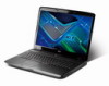
Acer Aspire 7230 Aspire 7230/7530/7530G Service Guide
Acer Aspire 7230 Manual
 |
View all Acer Aspire 7230 manuals
Add to My Manuals
Save this manual to your list of manuals |
Acer Aspire 7230 manual content summary:
- Acer Aspire 7230 | Aspire 7230/7530/7530G Service Guide - Page 1
Aspire 7230/7530/7530G Series Service Guide Service guide files and updates are available on the ACER/CSD web; for more information, please refer to http://csd.acer.com.tw PRINTED IN TAIWAN - Acer Aspire 7230 | Aspire 7230/7530/7530G Service Guide - Page 2
Revision History Please refer to the table below for the updates made on Aspire 7230/7530/7530G Series service guide. Date Chapter Updates II - Acer Aspire 7230 | Aspire 7230/7530/7530G Service Guide - Page 3
specifically disclaims any warranties of merchantability or fitness for any particular purpose. Any Acer Incorporated software described in this manual servicing, repair, and any incidental or consequential damages resulting from any defect in the software. Acer is a registered trademark of Acer - Acer Aspire 7230 | Aspire 7230/7530/7530G Service Guide - Page 4
are used in this manual: SCREEN MESSAGES Denotes actual messages that appear on screen. NOTE WARNING CAUTION IMPORTANT Gives bits and pieces of additional information related to the current topic. Alerts you to any damage that might result from doing or not doing specific actions. Gives - Acer Aspire 7230 | Aspire 7230/7530/7530G Service Guide - Page 5
supports, please read the following general information. 1. This Service Guide provides you with all technical information relating to the BASIC CONFIGURATION decided for Acer -on card, modem, or extra memory capability). These LOCALIZED FEATURES will NOT be covered in this generic service guide. In - Acer Aspire 7230 | Aspire 7230/7530/7530G Service Guide - Page 6
VI - Acer Aspire 7230 | Aspire 7230/7530/7530G Service Guide - Page 7
Easy-Launch Buttons 10 Touch Pad Basics (with fingerprint reader 11 Using the Keyboard 12 Lock Keys and embedded numeric keypad 12 Windows Keys 13 Hot Keys 14 Special Key 15 Using the System Utilities 16 Acer GridVista (dual-display compatible 16 Hardware Specifications and Configurations - Acer Aspire 7230 | Aspire 7230/7530/7530G Service Guide - Page 8
the Bluetooth board 80 Removing the Subwoofer Module 81 Removing the ExpressCard Module 83 Removing the Mainboard 85 Removing the CPU Fan Module 86 Removing the CPU 88 LCD Module Disassembly Process 89 LCD Module Disassembly Flowchart 89 Removing the LCD Bezel 90 Removing the Inverter Board - Acer Aspire 7230 | Aspire 7230/7530/7530G Service Guide - Page 9
View 157 Bottom View 158 Clearing Password Check and BIOS Recovery 159 Clearing Password Check 159 BIOS Recovery by Crisis Disk 160 FRU (Field Replaceable Unit) List 161 Aspire 7230/7530/7530G Exploded Diagram 162 Aspire 7230/7530/7530G FRU List 163 Screw List 171 Model Definition and - Acer Aspire 7230 | Aspire 7230/7530/7530G Service Guide - Page 10
Table of Contents X - Acer Aspire 7230 | Aspire 7230/7530/7530G Service Guide - Page 11
™ processor* • NVIDIA® nForce® MCP77MH • Acer InviLink™ 802.11b/g System Memory • Dual-Channel DDR2 SDRAM support • Up to 2 GB of DDR2 667 MHz memory, upgradeable to 4 GB using two soDIMM modules* TV Tuner • Digital TV-tuner supporting DVB-T* Display and graphics • 17" WXGA+ 1440 x 900 • NVIDIA - Acer Aspire 7230 | Aspire 7230/7530/7530G Service Guide - Page 12
) support for digital speakers Built-in microphone Dimensions and Weight • 402 (W) x 297 (D) x 41/43.9 (H) mm (15.83 x 11.69 x 1.61/1.73 inches) • 3.90 kg (8.59 lbs.) with 2 HDDs and 8-cell battery pack* • 3.80 kg (8.37 lbs.) with one HDD and 6-cell battery pack* Privacy control • Acer Bio - Acer Aspire 7230 | Aspire 7230/7530/7530G Service Guide - Page 13
) port • RF-in jack* • Headphones/speaker/line-out jack with S/PDIF support* • Microphone-in jack • Line-in jack • Ethernet (RJ-45) port • Modem (RJ-11) port • DC-in jack for AC adapter Environment • Temperature: • Operating: 5 °C to 35 °C • Non-operating: -20 °C to 65 °C • Humidity (non-condensing - Acer Aspire 7230 | Aspire 7230/7530/7530G Service Guide - Page 14
PCI-E Card NORTH BRIDGE & (Wireless LAN) SOUTH BRIDGE X1 Mini PCI-E Card (TV TUNER) USB2.0 x1 X1 Express Card (NEW CARD) USB2.0 x1 USB2.0 Ports x2 X1 LAN BroadCom PCIE-LAN BCM5787/5764 (10/100/GigaLAN) RJ45/RJ11 CABLE DOCK LAN/VGA/DVI/USB/AUDIO SN74CBTLV3257PWR Switch TS3DV520RHUR Switch SATA - Acer Aspire 7230 | Aspire 7230/7530/7530G Service Guide - Page 15
for sound recording. Display screen Power button Also called Liquid-Crystal Display (LCD), displays computer output. Turns the computer on and off. Easy-launch buttons Palmrest Status indicators Buttons for launching frequently used program. Comfortable support area for your hands when - Acer Aspire 7230 | Aspire 7230/7530/7530G Service Guide - Page 16
(left, center* and right) Touch Pad Keyboard Speakers Empowering key Description The left and right buttons function like the left and right mouse buttons. *The center button serves as Acer Bio-Protection fingerprint reader supporting Acer FingerNav 4-way control function (only for certain models - Acer Aspire 7230 | Aspire 7230/7530/7530G Service Guide - Page 17
Left View No. 1 2 3 4 5 6 7 Icon HDMI Item DC-in jack Ethernet (RJ-45) port Acer EasyPort IV connector External display (VGA) port HDMI USB 2.0 port Headphones/ speaker/line-out jack with S/PDIF support Microphone jack Description Connects to an AC adapter Connects to an Ethernet 10/100/1000- - Acer Aspire 7230 | Aspire 7230/7530/7530G Service Guide - Page 18
access Lights up when the optical drive is active. indicator Optical drive eject Ejects the optical disk from the drive. button Emergency eject hole Ejects the optical drive tray when the computer is turned off. Note: Insert a paper clip into the emergency eject hole to eject - Acer Aspire 7230 | Aspire 7230/7530/7530G Service Guide - Page 19
release latch Battery lock Releases the battery for removal. Locks the battery in position. Hard disk bay-Main Houses the computer's hard disk (secured with screws). Hard disk baySecondary Houses the computer's hard disk (secured with screws). Only for certain models. Memory compartment Houses - Acer Aspire 7230 | Aspire 7230/7530/7530G Service Guide - Page 20
Located beside the keyboard are application buttons. These buttons are called easy-launch buttons. They are: WLAN, Internet, email, Bluetooth, Arcade and Acer Empowering Technology. The mail and Web browser buttons are pre-set to email and Internet programs, but can be reset by users. To set the Web - Acer Aspire 7230 | Aspire 7230/7530/7530G Service Guide - Page 21
a mouse. Tapping on the Touch Pad is the same as clicking the left button. • Use Acer Bio-Protection fingerprint reader (3) supporting Acer FingerNav 4-way control function (only for certain models) or the 4-way scroll (3) button (only for certain models) to scroll up or down and move left or right - Acer Aspire 7230 | Aspire 7230/7530/7530G Service Guide - Page 22
embedded numeric keypad, separate cursor, lock, Windows, function and special keys. Lock Keys and embedded numeric keypad The keyboard has three lock keys which you can toggle be to connect an external keypad. When Scroll Lock is on, the screen moves one line up or down when you press the up or down - Acer Aspire 7230 | Aspire 7230/7530/7530G Service Guide - Page 23
keyboard has two keys that perform Windows-specific functions. Key Description Windows key Pressed alone, this key has the same effect as clicking on the Windows Start button network domain), or switch users (if you're not connected to a network domain) < > + : Minimizes all windows < > + - Acer Aspire 7230 | Aspire 7230/7530/7530G Service Guide - Page 24
computer's controls like screen brightness, volume output and the BIOS utility. To activate hot Acer eSettings Management in Acer Empowering Technology. Launches Acer ePower Management in Acer Empowering Technology. Puts the computer in Sleep mode. Switches display output between the display screen - Acer Aspire 7230 | Aspire 7230/7530/7530G Service Guide - Page 25
1. Open a text editor or word processor. 2. Hold and then press the key at the upper-center of the keyboard. NOTE: Note: Some fonts and software do not support the Euro symbol. Please refer to www.microsoft.com/ typography/faq/faq12.htm for more information. The US dollar sign 1. Open - Acer Aspire 7230 | Aspire 7230/7530/7530G Service Guide - Page 26
finger! For more information refer to the Acer Bio-Protection help files. Acer GridVista (dual-display compatible) NOTE: settings and click OK to complete the process. Acer GridVista is a handy utility that offers four pre-defined display settings so you can view multiple windows on the same screen - Acer Aspire 7230 | Aspire 7230/7530/7530G Service Guide - Page 27
, allowing two displays to be partitioned independently. AcerGridVista is simple to set up: 1. Run Acer GridVista and select your preferred screen configuration for each display from the task bar. 2. Drag and drop each window into the appropriate grid. 3. Enjoy the convenience of a well-organized - Acer Aspire 7230 | Aspire 7230/7530/7530G Service Guide - Page 28
for mobile systems. With HyperTransport™ 3 technology bus and on-chip memory controller • VCC_CORE0(based on CPU) • VCC_CORE1(based on CPU) • CPU_VDDNB (based on CPU) • VLDT 1.2V_HT • VDD I/O 1.8VSUS • CPU Memory Interface SMDDR_VTEM CPU Fan True Value Table Level Fan On Temp. 0 52 1 60 - Acer Aspire 7230 | Aspire 7230/7530/7530G Service Guide - Page 29
Socket S1 g2 CPU with full HT3 link • Support for PCI Express Base Specification, Gen 2 • Hybrid SLI support for simultaneous support of integrated and discrete GPUs for longer battery life in premium performance notebooks. • PCI Express x16 link interface for external graphics processors • Up to - Acer Aspire 7230 | Aspire 7230/7530/7530G Service Guide - Page 30
disk park control • ASF 2.0 support for remote manageability • Separately programmable spread spectrum support for key interfaces including LVDS, SATA, HT • AMD CPU PLL, CRTDAC, RGB DAC supply, USB Interface, CPU Interface • LAN MAC, Display Specification • 32.768Khz crystal for RTC inside MCP77 and - Acer Aspire 7230 | Aspire 7230/7530/7530G Service Guide - Page 31
size DIMM socket number Supports memory size per socket Supports maximum memory size Supports DIMM type Supports DIMM Speed Memory module combinations Memory Combinations Slot 1 0MB 0MB 0MB 512MB 512MB 512MB 1024MB 1024MB 1024MB 1024MB 2048MB 2048MB 2048MB 2048MB Specification Built-in 0MB (no - Acer Aspire 7230 | Aspire 7230/7530/7530G Service Guide - Page 32
Specification Vendor & model name Sony BC-5500S Performance Specification With CD Diskette With DVD Diskette Transfer rate (MB/sec) Sustained: Max 2.4 Mbytes/sec Sustained: Max 11 Mbytes/sec Buffer Memory Layer) and DVD-RW (Single Layer) discs DVD-RAM (Ver.2) CD-ROM CD-R CD-RW Loading - Acer Aspire 7230 | Aspire 7230/7530/7530G Service Guide - Page 33
SSOP Thermal sensor control Interface I2C bus, address: 98h BIOS Item BIOS vendor BIOS Version BIOS ROM type BIOS ROM size BIOS package Block size Supply Current Specification Phoenix BIOS code v0.3325 (for MP units) WND 1MB CMOS Boot Block Flash Memory 1MB 8 pins SOP 64kbytes per block • Active - Acer Aspire 7230 | Aspire 7230/7530/7530G Service Guide - Page 34
Screen Support Color Viewing Angle (degree) Horizontal: Right/Left Vertical: Upper/Lower Temperature Range (°C) Operating Storage (shipping) KBC Chipset Features Item Specification Specification WND WPCE775CA0DG • Share BIOS memory • Support for SPI flash memories • Flash page programing support - Acer Aspire 7230 | Aspire 7230/7530/7530G Service Guide - Page 35
RGB DAC supply, USB Interface, CPU Interface, LAN MAC, Display • MSI MS-V115A3-9MGS256 (256MB)/ Yuan YSTP621GP 1(256MB) • NVIDIA NB9M-GS (G3-64 package) • Featuring: • 16 Lane PCI Express support • LVDS Interface support • VGA support • Video out support • Upgradeable graphics • Power: 19V, 5V, 3.3V - Acer Aspire 7230 | Aspire 7230/7530/7530G Service Guide - Page 36
for direct power control of all types memory cards· • Support Spread Spectrum Clock for SD/MMC and MS/MSPRO/ HG to reduce EMI effect· • Support USB remote wake-up ability with memory card inserted and removal operation· • Provide Selective Suspend driver to reduce power consumption· • 48-pin LQFP - Acer Aspire 7230 | Aspire 7230/7530/7530G Service Guide - Page 37
. • Support wake on LAN meeting the ACPI requirements. • 68-pin QFN package. Specification FOXCON T60H928.11 Bluetooth miniUSB module • Internal Mini USB solution with antenna • Bluetooth 2.0+EDR • Bluetooth control for BT optical mouse Specification Aspire series: New Acer Non-Ergo Keyboard 104-key - Acer Aspire 7230 | Aspire 7230/7530/7530G Service Guide - Page 38
Card Chipset Features Item Specification Intel® Wireless WiFi Link 5100/5300 • The modem supports ITU-T V.92, V.90, V.34 (33600 bits/s), V.32bis and fallbacks. • It also supports Battery Item Vendor & model name Battery Type Pack capacity Number of battery cell Package configuration Specification - Acer Aspire 7230 | Aspire 7230/7530/7530G Service Guide - Page 39
. Please also refer to Chapter 4 Troubleshooting when problem arises. To activate the BIOS Utility, press F2 during POST (when "Press to enter Setup" message is prompted on the bottom of screen). Press F2 to enter setup. The default parameter of F12 Boot Menu is set to "disabled". If you want - Acer Aspire 7230 | Aspire 7230/7530/7530G Service Guide - Page 40
Setup Utility Information Main Advanced Security Boot Power Exit CPU Type: CPU Speed: AMD Turion(tm) Ultra Dual-Core Mobile ZM-82 2200 MHz IDE Model Name: IDE Serial Number: IDE1 Model Name: IDE1 Serial Number: ATAPI Model Name: System BIOS Version: VGA BIOS Version: Serial Number: Asset Tag - Acer Aspire 7230 | Aspire 7230/7530/7530G Service Guide - Page 41
Main The Main screen allows the user to set the system time and date as well as enable and disable boot option and recovery. Information Main System Time System Date PhoenixBIOS Setup Utility Advanced Security Boot Power [13:04:04] [05/15/2008] Exit Item Specific Help , , or < - Acer Aspire 7230 | Aspire 7230/7530/7530G Service Guide - Page 42
, menus, and submenus in this screen. Settings in boldface are the default and suggested parameter settings. Parameter USB Self-Healing Secured Setup Configuration Reset Configuration Data LPC Port 80 PCI Hot-Plug Resources I/O Memory Pre-fetchable Memory Description Enter the USB Self-Healing - Acer Aspire 7230 | Aspire 7230/7530/7530G Service Guide - Page 43
Memory Frequency • LS Table loading • ISO Flow Control • Hi Priority Channel • Display Refresh • Sync Flood Detection • USB Control • USB2 Control • USB BIOS Legacy Support Disk Access Mode • Local Bus IDE adapter XPrimary Master XPrimary Slave • Integrated Graphic • Video Memory • Hybrid Graphics - Acer Aspire 7230 | Aspire 7230/7530/7530G Service Guide - Page 44
parameters in this screen. Settings in boldface are the default and suggested parameter settings. Parameter Supervisor Password Is User Password Is SATA Port 0 Disk Status Set Supervisor Password Set User Password Set SATA Port 0 HDD Password Password on boot Description Shows the setting of the - Acer Aspire 7230 | Aspire 7230/7530/7530G Service Guide - Page 45
when typing your password because the characters do not appear on the screen. 3. Press Enter. After setting the password, the computer sets the User Password parameter to "Set". 4. If desired, you can opt to enable the Password on boot parameter. 5. When you are done, press F10 to save the changes - Acer Aspire 7230 | Aspire 7230/7530/7530G Service Guide - Page 46
5. If desired, you can enable the Password on boot parameter. 6. When you are done, press F10 to save the changes and exit the BIOS Setup Utility. If the verification is OK, the screen will display as following. The password setting is complete after the user presses Enter. If the current password - Acer Aspire 7230 | Aspire 7230/7530/7530G Service Guide - Page 47
disk drive and the DVD drive in the module bay. PhoenixBIOS Setup Utility Information Main Advanced Security Boot Power Boot KEY : 6: USB HDD : 7: USB CDROM : 8: IDE 6 : Excluded from boot order: Exit Item Specific Help Keys used to view or configure devices: Up and Down arrows select a device. - Acer Aspire 7230 | Aspire 7230/7530/7530G Service Guide - Page 48
Power The Power screen allows the user to configure various CPU and power management options and device wakeup behavior. PhoenixBIOS Setup Utility Information Main Advanced Security Boot Power Exit Item Specific Help C1E Configuration [Auto] Enable or Disable CPU Throttle: [Disabled] C1E - Acer Aspire 7230 | Aspire 7230/7530/7530G Service Guide - Page 49
Parameter PCI Clocks AltVid ASPM (L0s/L1s) PCIE Lane Swizzle Description Enable all PCI clocks or lock down all PCI clocks to Port 80. Enable or disable AltVid functionality. Enable or disable Active State Power Management (ASPM) states for L0s and L1. Enable or disable PCIE Lane Swizzle for PCIE x - Acer Aspire 7230 | Aspire 7230/7530/7530G Service Guide - Page 50
Exit The Exit screen allows you to save or discard any changes you made and quit the BIOS Utility. PhoenixBIOS Setup Utility Information Main Advanced Security Boot Power Exit Item Specific Help Exit Saving Changes Exit System Setup and Exit Discarding Changes save your changes to Load - Acer Aspire 7230 | Aspire 7230/7530/7530G Service Guide - Page 51
• Restore a BIOS when it becomes corrupted. Use the Phlash utility to update the system BIOS flash ROM. NOTE: If you do not have a crisis recovery diskette at hand, then you should create a Crisis Recovery Diskette before you use the Phlash utility. NOTE: Do not install memory-related drivers (XMS - Acer Aspire 7230 | Aspire 7230/7530/7530G Service Guide - Page 52
Utility This section provide you with removing HDD/BIOS method: Remove HDD Password: If you key in the wrong HDD password three times, HDD password error code displays. See the image below. To reset the HDD password, run HDD_PW.EXE as follows: 1. Key in hdd_pw 15494 0 2. Press 2. 3. Select one upper - Acer Aspire 7230 | Aspire 7230/7530/7530G Service Guide - Page 53
Remove BIOS Password: If you key in the wrong Supervisor Password three times, System Disabled displays on the screen. See the image below. To reset the BIOS password, run BIOS_PW.EXE as follows: 1. Key in bios_pw 14452 0 2. Select one string from the list. Chapter 2 43 - Acer Aspire 7230 | Aspire 7230/7530/7530G Service Guide - Page 54
3. Reboot the system and key in the selected string (qjjg9vy, 07yqmjd etc.) for the BIOS user password. 44 Chapter 2 - Acer Aspire 7230 | Aspire 7230/7530/7530G Service Guide - Page 55
and Replacement This chapter contains step-by-step procedures on how to disassemble the notebook computer for maintenance and troubleshooting. Disassembly Requirements To disassemble the computer, you need the following tools: • Wrist grounding strap and conductive mat for preventing electrostatic - Acer Aspire 7230 | Aspire 7230/7530/7530G Service Guide - Page 56
Instructions Before proceeding with the disassembly procedure, make sure that you do the following: 1. Turn off the power to the system and all peripherals. 2. Unplug the AC adapter and all power and signal cables from the system. 3. Place the system on a flat, stable surface. 4. Remove the battery - Acer Aspire 7230 | Aspire 7230/7530/7530G Service Guide - Page 57
The flowchart below gives you a graphic representation on the entire disassembly sequence and instructs you on the components that need to be removed during servicing. For example, if you want to remove the main board, you must first remove the keyboard, then disassemble the inside assembly frame in - Acer Aspire 7230 | Aspire 7230/7530/7530G Service Guide - Page 58
Pack 1. Turn computer over. 2. Slide the battery lock/unlock latch to the unlock position. 3. Slide and hold the battery release latch to the release position (1), then slide out the battery pack from the main unit (2). 2 1 Removing the SD dummy card 1. Push the SD dummy card all the way in to eject - Acer Aspire 7230 | Aspire 7230/7530/7530G Service Guide - Page 59
2. Pull it out from the slot. Removing the ExpressCard dummy card 1. Push the ExpressCard dummy card all the way in to eject it. 2. Pull it out from the slot. Chapter 3 49 - Acer Aspire 7230 | Aspire 7230/7530/7530G Service Guide - Page 60
Removing the Lower Covers 1. See "Removing the Battery Pack" on page 48. 2. Loosen the ten captive screws from the Memory, HDD1, and HDD2 Covers. HDD1 Cover 3. Carefully open the memory cover. Memory Cover HDD2 Cover 4. Remove the HDD1 cover as shown. 50 Chapter 3 - Acer Aspire 7230 | Aspire 7230/7530/7530G Service Guide - Page 61
5. Remove the HDD2 cover as shown. Removing the DIMM Modules 1. Remove the battery. See "Removing the Battery Pack" on page 48. 2. Remove the Memory Module cover. See "Removing the Lower Covers" on page 50. 3. Push out the release latches on both sides of the DIMM socket to release the - Acer Aspire 7230 | Aspire 7230/7530/7530G Service Guide - Page 62
Removing the MXM Module 1. Remove the battery. See "Removing the Battery Pack" on page 48. 2. Remove the four securing screws. Step MXM Module Size M2.5*9 (NL) 3. Grasp the module and remove. Quantity 4 Screw Type 52 Chapter 3 - Acer Aspire 7230 | Aspire 7230/7530/7530G Service Guide - Page 63
Removing the TV Tuner module 1. See "Removing the Battery Pack" on page 48. 2. Remove the HDD2 cover. See "Removing the Lower Covers" on page 50. 3. Disconnect the TV Tuner cable from the module. 4. Remove - Acer Aspire 7230 | Aspire 7230/7530/7530G Service Guide - Page 64
TV Tuner module. NOTE: Some models come equipped with either a TV Tuner module or a Turbo RAM module. 6. Remove the bracket from the module. Removing the WLAN Module 1. Remove the battery. See "Removing the Battery Pack" on page 48. 2. Remove the Tv Tuner module. See "Removing the TV Tuner module - Acer Aspire 7230 | Aspire 7230/7530/7530G Service Guide - Page 65
4. Move the cables to avoid damaging them, and remove the two securing screws to release the WLAN board. Step WLAN Module Size M2*3 Quantity 2 5. Detach the WLAN board from the WLAN socket. Screw Type Chapter 3 55 - Acer Aspire 7230 | Aspire 7230/7530/7530G Service Guide - Page 66
Removing the Hard Disk Drive Module 1. Remove the Battery Pack. See "Removing the Battery Pack" on page 48. 2. Remove the HDD1 cover. See "Removing the Lower Covers" on page 50. 3. Remove the two securing screws. Step HDD Size M2*3 - Acer Aspire 7230 | Aspire 7230/7530/7530G Service Guide - Page 67
5. Remove the four screws (two on each side) securing the HDD to the carrier. Step HDD Carrier Size M3*0.5+3.5 Quantity 4 6. Turn the HDD module upside down, and lift the HDD carrier up. Screw Type 7. Remove the connector from the HDD. Chapter 3 57 - Acer Aspire 7230 | Aspire 7230/7530/7530G Service Guide - Page 68
Removing the Optical Drive Module 1. Remove the Battery Pack. See "Removing the Battery Pack" on page 48. 2. Loosen the captive screw securing the ODD module and remove the ODD cap. 3. Carefully use a screwdriver to push the locking catch - Acer Aspire 7230 | Aspire 7230/7530/7530G Service Guide - Page 69
5. Remove the two screws securing the ODD bracket and remove the ODD bracket from the optical disk drive module. Step ODD Bracket Size M2*2.5 Quantity 2 6. Insert a pin in the eject hole of the ODD to eject the ODD tray. Screw Type 7. Press - Acer Aspire 7230 | Aspire 7230/7530/7530G Service Guide - Page 70
Main Unit Disassembly Process Main Unit Disassembly Flowchart Screw List Step Switch Cover Switch Board Modem Module LCD Module Upper Cover Touch Pad Bracket Screw M2.5*3 M2.5*6.5 M2*3 M2*3 M2.5*6.5 M2.5*6.5 M2.5*3 M2.5*6.5 M2*3 M2.5*3 M2*3 60 Quantity 4 5 2 2 2 4 1 11 1 4 4 - Acer Aspire 7230 | Aspire 7230/7530/7530G Service Guide - Page 71
Step Launch Board Speaker eKey Board Bluetooth Board Subwoofer ExpressCard Module Mainboard CPU Fan Screw M2*3 M2.5*6.5 M2*3 M2*3 M2.5*3 M2*3 M2.5*6.5 M2.5*6.5 Quantity 4 4 2 1 4 2 1 1 Part No. 86.ARE07.002 86.ARE07.001 86.ARE07.002 86.ARE07.002 - Acer Aspire 7230 | Aspire 7230/7530/7530G Service Guide - Page 72
It is recommended that only fingers are used to remove the Switch Cover. 1. Remove the Battery Pack. See "Removing the Battery Pack" on page 48. 2. Locate and remove the nine securing screws as shown. Step Switch Cover Switch Cover Size M2.5*3 Blue Callout M2.5*6.5 Red Callout Quantity 4 5 Screw - Acer Aspire 7230 | Aspire 7230/7530/7530G Service Guide - Page 73
and remove the FFC cable on the left as shown. 3. Disconnect both cables on the right as shown. 4. Remove the two securing screws from the Switch Board and lift the board clear. Step Switch Board Size M2*3 (NL) Quantity 2 Screw Type Chapter 3 63 - Acer Aspire 7230 | Aspire 7230/7530/7530G Service Guide - Page 74
Removing the Keyboard 1. Remove the Switch Cover. See "Removing the Switch Cover" on page 62. 2. Grasp the keyboard and turn it over to expose the FFC cable. 3. Lift up the locking lever and remove the FFC cable. 4. Remove the keyboard and place it on a clean surface. 64 Chapter 3 - Acer Aspire 7230 | Aspire 7230/7530/7530G Service Guide - Page 75
Removing the Modem Module 1. Remove the Keyboard. See "Removing the Keyboard" on page 64. 2. Remove the two securing screws. Step Modem Module Size M2*3 (NL) Quantity 2 Screw Type 3. Using a plastic pry, partially lift up the module - Acer Aspire 7230 | Aspire 7230/7530/7530G Service Guide - Page 76
the WLAN Module" on page 54. 2. Remove the memory cover. See "Removing the Lower Covers" on page 50. 3. Remove the Keyboard. See "Removing the Keyboard" on page 64. 4. Gently pull the Antenna Cables , disconnect all three cables at this time to disassemble the upper and lower bases. 66 Chapter 3 - Acer Aspire 7230 | Aspire 7230/7530/7530G Service Guide - Page 77
6. Gently pull the MIC cable through the HDD housing. 7. Turn the computer on its side, and feed the cables through to the upperside. 8. Pull the cables completely through. Chapter 3 67 - Acer Aspire 7230 | Aspire 7230/7530/7530G Service Guide - Page 78
Removing the LCD Module 1. Remove the Memory Cover. See "Removing the Lower Covers" on page 50. 2. Remove the WLAN Module. See "Removing the WLAN Module" on page 54. 3. Disconnect the Antenna, MIC - Acer Aspire 7230 | Aspire 7230/7530/7530G Service Guide - Page 79
6. Disconnect the LCD back light cable as shown. 7. Remove the single ground screw and four securing screws (two each side) connecting the LCD module. Step LCD Module Ground Size M2.5*6.5 (NL) Red Callout M2.5*3 (NL) Blue Callout Quantity 4 1 8. Carefully remove the LCD module from the chassis. - Acer Aspire 7230 | Aspire 7230/7530/7530G Service Guide - Page 80
screws on the bottom panel. Step Upper Cover Size M2.5*6.5 Quantity 11 Screw Type 3. Turn the computer over and remove the securing screw from the keyboard plate. Step DDR Plate Size M2*3 Quantity 1 Screw Type 70 Chapter 3 - Acer Aspire 7230 | Aspire 7230/7530/7530G Service Guide - Page 81
4. Remove the keyboard plate. If necessary, use a plastic pry to lift the plate. 5. Disconnect the five cables from the mainboard as shown. A B E C D IMPORTANT:When removing cables, always hold - Acer Aspire 7230 | Aspire 7230/7530/7530G Service Guide - Page 82
Release the securing latches and disconnect C as Release the securing latches and disconnect D as shown. shown. Release the securing latches and disconnect E as shown. 6. Remove the four securing screws from the upper cover. Step Upper Cover Size M2.5*3 Quantity 4 Screw Type 72 Chapter 3 - Acer Aspire 7230 | Aspire 7230/7530/7530G Service Guide - Page 83
7. Grasp the Upper Cover by the hinge socket and pry it open. Do not lift the cover completely off. NOTE: Do not try to pry open more than one edge at a time. 8. While holding the cover open, pull through any remaining cables. 9. Grasp the cover by the opposite edge and lift up to remove the Upper - Acer Aspire 7230 | Aspire 7230/7530/7530G Service Guide - Page 84
Removing the Finger Print Reader 1. Remove the Upper Cover. See "Removing the Upper Cover" on page 70. 2. Disconnect the cable as shown. 3. Disconnect the two FFC cables as shown. 4. Remove the four securing screw from the Finger Print Reader board. Step Finger Print Reader Size M2*3 Quantity 4 - Acer Aspire 7230 | Aspire 7230/7530/7530G Service Guide - Page 85
5. Remove the bracket from the board. 6. Remove the Finger Print Reader board from the Upper Cover. Chapter 3 75 - Acer Aspire 7230 | Aspire 7230/7530/7530G Service Guide - Page 86
Removing the Touch Pad 1. Remove the Upper Cover. See "Removing the Upper Cover" on page 70. 2. Disconnect the Touch Pad cable from the Touch Pad board. IMPORTANT:The Touch Pad cannot be removed individually. To replace the Touch Pad, replace the entire Upper Cover. 76 Chapter 3 - Acer Aspire 7230 | Aspire 7230/7530/7530G Service Guide - Page 87
Removing the Launch Board 1. Remove the Upper Cover. See "Removing the Upper Cover" on page 70. 2. Lift up the locking latch and remove the FFC cable as shown. 3. Remove the four screws from the Launch Board. Step Launch Board Size M2*3 Quantity 4 4. Remove the Launch Board from the Upper Cover. - Acer Aspire 7230 | Aspire 7230/7530/7530G Service Guide - Page 88
Removing the Speaker Module 1. Remove the Upper Cover. See "Removing the Upper Cover" on page 70. 2. Remove four securing screws connecting the Speaker Module. Step Speaker Module Size M2*6 Quantity 4 3. Remove the Speaker Module from the upper cover. Screw Type 78 Chapter 3 - Acer Aspire 7230 | Aspire 7230/7530/7530G Service Guide - Page 89
Removing the eKey Board 1. Remove the Upper Cover. See "Removing the Upper Cover" on page 70. 2. Turn the Upper Cover upside down and remove the two securing screws connecting the eKey board. 3. Disconnect the eKey Board cable. Step eKey Board Size M2*3 4. Remove the board as shown. Quantity 2 - Acer Aspire 7230 | Aspire 7230/7530/7530G Service Guide - Page 90
1. Remove the Upper Cover. See "Removing the Upper Cover" on page 70. 2. Remove the securing screw from the Bluetooth board. Step Bluetooth Board Size M2*3 Quantity 1 3. Disconnect the mainboard to bluetooth cable as shown. Screw Type 4. Disconnect the cable from the mainboard. 80 Chapter 3 - Acer Aspire 7230 | Aspire 7230/7530/7530G Service Guide - Page 91
the Subwoofer Module. Step Subwoofer Module Size M2.5*4 Quantity 4 Screw Type 3. Grasp the cable by the end and guide it out of its housing as shown in the following images. IMPORTANT:The housing guides are hooked to hold the cable in place. Do not pull the cable to remove it or damage - Acer Aspire 7230 | Aspire 7230/7530/7530G Service Guide - Page 92
4. Grasp the Subwoofer Module and lift it up to remove. 82 Chapter 3 - Acer Aspire 7230 | Aspire 7230/7530/7530G Service Guide - Page 93
Removing the ExpressCard Module 1. See "Removing the Upper Cover" on page 70. 2. Disconnect the cable connecting the ExpressCard module. IMPORTANT:Do not grasp the cable itself to prevent fraying. 3. Remove the two securing screws. Step ExpressCard Module Size M2*3 Quantity 2 Screw Type - Acer Aspire 7230 | Aspire 7230/7530/7530G Service Guide - Page 94
4. Lift the ExpressCard module away from the upper cover. 84 Chapter 3 - Acer Aspire 7230 | Aspire 7230/7530/7530G Service Guide - Page 95
Removing the Mainboard 1. Remove the Upper Cover. See "Removing the Upper Cover" on page 70. 2. Disconnect the two cables connected to the motherboard. 3. Remove the securing screw from the Mainboard. Step Mainboard Size M2.5*6.5 Quantity 1 Screw Type 4. Pull the edge of the lower base outward - Acer Aspire 7230 | Aspire 7230/7530/7530G Service Guide - Page 96
Removing the CPU Fan Module 1. See "Removing the Battery Pack" on page 48. 2. Remove the Mainboard. See "Removing the Mainboard" on page 85. 3. Turn the Mainboard right side up, and place it on a clean - Acer Aspire 7230 | Aspire 7230/7530/7530G Service Guide - Page 97
6. Lift the cover to expose the single securing screw. Remove the screw. Step CPU Fan Module Size M2.5*6.5 Quantity 1 7. Lift the Fan module clear of the Mainboard. Screw Type Chapter 3 87 - Acer Aspire 7230 | Aspire 7230/7530/7530G Service Guide - Page 98
Removing the CPU 1. Remove the CPU Fan Module. See "Removing the CPU Fan Module" on page 86. 2. Using a flat screwdriver, turn the CPU socket latch clockwise 180° to release the CPU. k 3. Lift the CPU clear of the Mainboard. 88 Chapter 3 - Acer Aspire 7230 | Aspire 7230/7530/7530G Service Guide - Page 99
LCD Module Disassembly Process LCD Module Disassembly Flowchart Screw List Step LCD Bezel Camera Module LCD Panel LCD Brackets Screw M2.5*6.5 M2*3 M2.5*6.5 M2*3 Quantity 6 1 6 8 Part No. 86.ARE07.001 86.ARE07.002 86.ARE07.001 86.ARE07.002 Chapter 3 89 - Acer Aspire 7230 | Aspire 7230/7530/7530G Service Guide - Page 100
Removing the LCD Bezel 1. Remove the LCD Module. See "Removing the LCD Module" on page 68. 2. Remove the six rubber covers and screws. Step LCD Bezel Size M2.5*6.5 Quantity 6 Screw Type 3. Starting from the inside edges, pry the inside of the bezel upwards from the panel. Continue moving left - Acer Aspire 7230 | Aspire 7230/7530/7530G Service Guide - Page 101
4. Lift up the bezel and remove it from the LCD Module. Chapter 3 91 - Acer Aspire 7230 | Aspire 7230/7530/7530G Service Guide - Page 102
Removing the Inverter Board 1. Remove the LCD Bezel. See "Removing the LCD Bezel" on page 90. 2. Disconnect the left and right Inverter board cables as shown. 3. Lift up the Inverter Board and remove. 92 Chapter 3 - Acer Aspire 7230 | Aspire 7230/7530/7530G Service Guide - Page 103
Removing the Camera Module 1. Remove the LCD Bezel. See "Removing the LCD Bezel" on page 90. 2. Remove the two securing screws from the Camera Module. Step Camera Module Size M2*3 Quantity 1 3. Disconnect the Camera Module cable as shown. Screw Type Chapter 3 93 - Acer Aspire 7230 | Aspire 7230/7530/7530G Service Guide - Page 104
page 90. 2. Remove the six securing screws from the LCD Module. Step LCD Panel Size M2.5*6.5 Quantity 6 3. Disconnect the left and right sides of the Inverter cable. Screw Type 4. Disconnect the Camera Module cable as shown. 94 Chapter 3 - Acer Aspire 7230 | Aspire 7230/7530/7530G Service Guide - Page 105
5. Grasp the panel by both ends and lift to remove. Chapter 3 95 - Acer Aspire 7230 | Aspire 7230/7530/7530G Service Guide - Page 106
Removing the LCD Brackets and FPC Cable 1. Remove the LCD Panel. See "Removing the LCD Panel" on page 94. 2. Turn the LCD panel over to expose the rear. Grip the FPC cable and lift upward to detach the adhesive pads. 3. Remove the eight securing screws (four on each side) from the LCD Panel brackets - Acer Aspire 7230 | Aspire 7230/7530/7530G Service Guide - Page 107
4. Remove the LCD brackets by pulling away from the LCD Panel as shown. Chapter 3 97 - Acer Aspire 7230 | Aspire 7230/7530/7530G Service Guide - Page 108
LCD Module Reassembly Procedure Replacing the LCD Panel 1. Align the LCD brackets with the eight screw holes (four on each side) on the LCD Panel as shown. 2. Secure the LCD brackets to the LCD panel. 3. Turn the panel over. Insert the LCD Panel cable into the LCD Panel as shown. 98 Chapter 3 - Acer Aspire 7230 | Aspire 7230/7530/7530G Service Guide - Page 109
4. Align the LCD Panel cable as shown and press down to secure in place. 5. Take care to insert the top of the panel fist and then 6. Place the LCD Panel in the back cover. angle the it in place. 7. Secure the LCD module with the six securing screws. Chapter 3 99 - Acer Aspire 7230 | Aspire 7230/7530/7530G Service Guide - Page 110
8. Connect the left and right Inverter cables. 9. Connect the camera cable. 100 Chapter 3 - Acer Aspire 7230 | Aspire 7230/7530/7530G Service Guide - Page 111
Replacing the LCD Bezel 1. Starting from the bottom, locate the bezel correctly and press down the edges until there are no gaps between the bezel and the LCD Module, 2. Replace the six screws and the rubber screw caps provided. Chapter 3 101 - Acer Aspire 7230 | Aspire 7230/7530/7530G Service Guide - Page 112
Main Module Reassembly Procedure Replacing the CPU 1. Carefully turn the mainboard upside down (CPU 2. Using a plastic screw driver, lock the CPU in the side up), and insert the CPU into the CPU bracket socket as shown. as shown. Replacing the CPU Fan Module 1. Replace the Fan module on the - Acer Aspire 7230 | Aspire 7230/7530/7530G Service Guide - Page 113
3. Tighten the four (4) captive screws on the heatsink. 4. Connect the Fan cable to the Mainboard. Chapter 3 103 - Acer Aspire 7230 | Aspire 7230/7530/7530G Service Guide - Page 114
the Mainboard 1. Pull the edge of the lower base outward and insert 2. Replace the securing screw on the Mainboard. the motherboard in the lower base. 3. Connect the two cables on the mainboard side. Replacing the Bluetooth Board 1. Insert the module into the alignment pin and press 2. Connect the - Acer Aspire 7230 | Aspire 7230/7530/7530G Service Guide - Page 115
Replacing the ExpressCard Module 1. Replace the ExpressCard module on the upper cover. 2. Replace the two securing screws. IMPORTANT:The correct location of the ExpressCard Module screws is illustrated in the following image. Do not insert the screws in the remaining screw sockets. They are - Acer Aspire 7230 | Aspire 7230/7530/7530G Service Guide - Page 116
Replacing the Subwoofer Module 1. Grasp the Subwoofer Module and insert in the lower base. 2. Insert the cables under the housing guide as shown. 3. Replace the four securing screws on the Subwoofer Module. 106 Chapter 3 - Acer Aspire 7230 | Aspire 7230/7530/7530G Service Guide - Page 117
Replacing the Finger Print Reader 1. Remove the Finger Print Reader board from the Upper Cover. 2. Remove the bracket from the board. 3. Replace the four securing screw on the Finger Print Reader board. NOTE: Move back the cabling to allow for easier access to the screw sockets. Chapter 3 107 - Acer Aspire 7230 | Aspire 7230/7530/7530G Service Guide - Page 118
4. Connect the two FFC cables as shown. 5. Connect the cable as shown. 108 Chapter 3 - Acer Aspire 7230 | Aspire 7230/7530/7530G Service Guide - Page 119
Replacing the eKey Board IMPORTANT:Take note of the eKey button when installing. It must face down and the cable connector up in order to install the module correctly. 1. Locate and replace the board as shown. 2. Connect the eKey Board cable and replace the two securing screws. Chapter 3 109 - Acer Aspire 7230 | Aspire 7230/7530/7530G Service Guide - Page 120
Replacing the Touch Pad IMPORTANT:The Touch Pad cannot be removed individually. To replace the Touch Pad, replace the entire Upper Cover. 1. Connect the Touch Pad cable as shown Replacing the Launch Board 1. Replace the Launch Board on the upper cover. 2. Replace the four securing screws. 3. - Acer Aspire 7230 | Aspire 7230/7530/7530G Service Guide - Page 121
Replacing the Finger Print Reader 1. Replace the Finger Print Reader board on the Upper Cover. 2. Replace the bracket on the board. 3. Replace the four securing screw on the Finger Print Reader board. NOTE: Move back the cabling to allow for easier access to the screw sockets. Chapter 3 111 - Acer Aspire 7230 | Aspire 7230/7530/7530G Service Guide - Page 122
4. Connect the two FFC cables as shown. 5. Connect the cable as shown. Replacing the Upper Cover 1. Locate the upper cover over the lower base taking note of the screw sockets. 112 Chapter 3 - Acer Aspire 7230 | Aspire 7230/7530/7530G Service Guide - Page 123
2. Angle the right end of the Upper Cover in place, and insert any remaining cables through the lower base as shown. 3. Set the Upper Cover down on the lower base. 4. Replace the four securing screws on the Upper Cover. Chapter 3 113 - Acer Aspire 7230 | Aspire 7230/7530/7530G Service Guide - Page 124
5. Connect the five cables to the mainboard as shown. A B E C D IMPORTANT:When replacing cables, always hold the cable by the pull-tab or by the connector. Do not hold the pull by the cable itself to prevent stripping. Connect A as shown. Connect B as shown. Connect C as shown. Connect D as - Acer Aspire 7230 | Aspire 7230/7530/7530G Service Guide - Page 125
Connect E as shown. 6. Angle the keyboard plate and insert as shown. 7. Replace the securing screw on the keyboard plate. 8. Turn the computer upside down and replace the eleven securing screws on the bottom panel to attach the bottom and lower covers. Chapter 3 115 - Acer Aspire 7230 | Aspire 7230/7530/7530G Service Guide - Page 126
Replacing the LCD Module 1. Replace the LCD Module on the Lower Case as shown. 2. Replace the single ground screw and four securing screws (two each side) connecting the LCD module. 3. Replace the LCD Interface and back light cables as shown. 116 Chapter 3 - Acer Aspire 7230 | Aspire 7230/7530/7530G Service Guide - Page 127
4. Turn the computer over and replace the two securing screws. Replacing the Antenna, MIC and Speaker Cables IMPORTANT:Ensure that all cables pass through the Mainboard and are accessible from the underside of lower cover. 1. Insert the cabling through the housing as shown. 2. Ensure that the - Acer Aspire 7230 | Aspire 7230/7530/7530G Service Guide - Page 128
4. Place the computer upside down, and insert the MIC and Speaker cables through the HDD housing. 5. Take note of the cabling arrangement. Ensure that the cabling is secured as shown to prevent damage. 6. Connect the MIC and speaker cables. 118 Chapter 3 - Acer Aspire 7230 | Aspire 7230/7530/7530G Service Guide - Page 129
7. Gently pull the Antenna Cables through the HDD housing. Replacing the Modem Module 1. Angle the Modem Module as shown and attach to the connector. 2. Insert the module and replace the two securing screws. Chapter 3 119 - Acer Aspire 7230 | Aspire 7230/7530/7530G Service Guide - Page 130
Replacing the Keyboard 1. Replace the keyboard cable to the mainboard, and 2. Turn the keyboard over and place the front edge secure the locking latch. first in the mounting. 3. Press down on the areas marked below to secure in place. 120 Chapter 3 - Acer Aspire 7230 | Aspire 7230/7530/7530G Service Guide - Page 131
Replacing the Switch Board 1. Reseat the Switch Board and replace the two securing screws. 2. Connect both cables on the right as shown. 3. Replace the FFC cable on the left as shown and close the locking latch. Chapter 3 121 - Acer Aspire 7230 | Aspire 7230/7530/7530G Service Guide - Page 132
Replacing the Switch Cover 1. Replace the Switch cover, and press down to secure in place. 2. Turn the computer over and replace the nine securing screws. 122 Chapter 3 - Acer Aspire 7230 | Aspire 7230/7530/7530G Service Guide - Page 133
. 3. Slide Module in chassis and press until Module is 4. Replace the ODD Cap and secure the single flush with chassis. captive screw. Replacing the Hard Disk Drive Module 1. Replace the connector on the HDD. 2. Place the HDD in the HDD carrier. Chapter 3 123 - Acer Aspire 7230 | Aspire 7230/7530/7530G Service Guide - Page 134
3. Replace the four screws (two each side) to secure 4. Insert the HDD, left side first, and push down to the carrier. locate the interface correctly. 5. Replace the two securing screws. 124 Chapter 3 - Acer Aspire 7230 | Aspire 7230/7530/7530G Service Guide - Page 135
two securing screws. 3. Replace the two antenna cables. NOTE: The following is the correct cable-color to connector designation: TR1 to Gray and TR2 to Black. Replacing the TV Tuner Module 1. Attach the bracket to the module. 2. Insert the TV Tuner board in to the socket. Chapter 3 125 - Acer Aspire 7230 | Aspire 7230/7530/7530G Service Guide - Page 136
3. Replace the two securing screws. 4. Replace the antenna cable. Replacing the MXM Module 1. Insert the MXM board in to the socket. 2. Replace the four securing screws. Replacing the DIMM Modules 1. Insert DIMM in to the socket. 2. Press down to locate DIMM correctly. 3. Repeat steps 1 and 2 - Acer Aspire 7230 | Aspire 7230/7530/7530G Service Guide - Page 137
Replacing the Lower Covers 1. Replace the HDD2 cover. 2. Replace the HDD1 cover. 3. Replace the Memory cover. 4. Secure the ten captive screws in the covers. Replacing the ExpressCard Dummy Tray 1. Insert the ExpressCard dummy as shown. 2. Push into the slot until - Acer Aspire 7230 | Aspire 7230/7530/7530G Service Guide - Page 138
Dummy Tray 1. Insert the SD dummy as shown. 2. Push into the slot until flush with the chassis cover. Replacing the Battery 1. Slide and hold the battery release latch (1), insert 2. Slide the battery lock/unlock latch to the lock battery in to the main unit (2). position. 2 1 128 Chapter 3 - Acer Aspire 7230 | Aspire 7230/7530/7530G Service Guide - Page 139
Troubleshooting Chapter 4 Common Problems Use the following procedure as a guide for computer problems. NOTE: The diagnostic tests are intended to test only Acer products. Non-Acer products, prototype cards, or modified options can give false errors and invalid system responses. 1. Obtain the - Acer Aspire 7230 | Aspire 7230/7530/7530G Service Guide - Page 140
(see "Thermal Unit Failure" on page 144) and fan airways are free of obstructions. 5. Disable the power management settings in the BIOS to ensure they are not the cause of the problem (see "Boot" on page 37). 6. Remove all external and non-essential hardware connected to the computer that are not - Acer Aspire 7230 | Aspire 7230/7530/7530G Service Guide - Page 141
cards and CD/DVD discs. Restart the computer. If the computer boots correctly, add the devices one by one until the failure point is discovered. 6. Reseat the memory modules. 7. Remove the drives (see "Disassembly Process" on page 46). 8. If the Issue is still not resolved, see "Online Support - Acer Aspire 7230 | Aspire 7230/7530/7530G Service Guide - Page 142
same locations on the screen), the LCD is faulty and should be replaced. See "Disassembly Process" on page 46. 4. Adjust the brightness to its highest level. See the User Manual for instructions on adjusting settings. NOTE: Ensure that the computer is not running on battery alone as this may reduce - Acer Aspire 7230 | Aspire 7230/7530/7530G Service Guide - Page 143
If the LCD fails, perform the following actions one at a time to correct the problem. Do not replace a nondefective FRUs: Built-In Keyboard Failure If the built-in Keyboard fails, perform the following actions one at a time to correct the problem. Do not replace a non-defective FRUs: Chapter 4 133 - Acer Aspire 7230 | Aspire 7230/7530/7530G Service Guide - Page 144
Pad doesn't work, perform the following actions one at a time to correct the problem. Do not replace a non-defective FRUs: Internal Speaker Failure If the internal Speakers fail, perform the following actions one at a time to correct the problem. Do not replace a non-defective FRUs: 134 Chapter 4 - Acer Aspire 7230 | Aspire 7230/7530/7530G Service Guide - Page 145
no device conflicts. • No hardware is listed under Other Devices. 3. Roll back the audio driver to the previous version, if updated recently. 4. Remove and reinstall the audio driver. 5. Ensure that all volume controls are set mid range: a. Click the volume icon on the taskbar and drag the slider to - Acer Aspire 7230 | Aspire 7230/7530/7530G Service Guide - Page 146
time to correct the problem. Do not replace a non-defective FRUs: Microphone Problems If internal or external Set up microphone. c. Select the microphone type from the list and click Next. d. Follow the onscreen prompts to complete the test. 8. If the Issue is still not resolved, see "Online Support - Acer Aspire 7230 | Aspire 7230/7530/7530G Service Guide - Page 147
to resolve the problem. 4. Run the Windows Memory Diagnostic Tool. For more information see Windows Help and Support. 5. Restart the computer and press F2 to enter the BIOS Utility. Check the BIOS settings are correct and that CD/DVD drive is set as the first boot device on the Boot menu. 6. Ensure - Acer Aspire 7230 | Aspire 7230/7530/7530G Service Guide - Page 148
: • Not shown in My Computer or the BIOS setup • LED does not flash when the computer starts up • The tray does not eject • Access failure screen displays • The ODD is noisy Perform the following general solutions one at a time to correct the problem. 1. Reboot the computer and retry the operation - Acer Aspire 7230 | Aspire 7230/7530/7530G Service Guide - Page 149
reinstall the driver. d. Windows factory default. If using different software, refer to the software's user manual problem. 1. Check that system resources are not running low: a. Try closing some applications. b. Reboot and try the operation again. 2. Check that the ODD controller transfer mode is set - Acer Aspire 7230 | Aspire 7230/7530/7530G Service Guide - Page 150
to one of the ODDs specified in "Hardware Specifications and Configurations" on page 18. 3. Turn off the power and remove the cover to inspect the connections to the ODD. See "Disassembly Process" on page 46. a. Check for broken connectors on the drive, motherboard, and cables. b. Check for bent or - Acer Aspire 7230 | Aspire 7230/7530/7530G Service Guide - Page 151
USB port fails, perform the following actions one at a time to correct the problem. Do not replace a non-defective FRUs: Modem Function Failure If the internal Modem fails, perform the following actions one at a time to correct the problem. Do not replace a non-defective FRUs: Chapter 4 141 - Acer Aspire 7230 | Aspire 7230/7530/7530G Service Guide - Page 152
Wireless Function Failure If the WLAN fails, perform the following actions one at a time to correct the problem. Do not replace a nondefective FRUs: EasyTouch Button Failure If the Acer EasyTouch buttons fail, perform the following actions one at a time to correct the problem. Do not replace a non- - Acer Aspire 7230 | Aspire 7230/7530/7530G Service Guide - Page 153
Failure If the Acer MediaTouch buttons fail, perform the following actions one at a time to correct the problem. Do not replace a non-defective FRUs: Fingerprint Reader Failure If the Fingerprint Reader fails, perform the following actions one at a time to correct the problem. Do not replace a non - Acer Aspire 7230 | Aspire 7230/7530/7530G Service Guide - Page 154
If the Thermal Unit fails, perform the following actions one at a time to correct the problem. Do not replace a non-defective FRUs: HDTV Switch Failure If the HDTV Switch fails, perform the following actions one at a time to correct the problem. Do not replace a non-defective FRUs: 144 Chapter 4 - Acer Aspire 7230 | Aspire 7230/7530/7530G Service Guide - Page 155
using System Restore. If the issue is not fixed, repeat the preceding steps and select an earlier time and date. 9. Run the Event Viewer to check the events log for errors. For more information see Windows Help and Support. 10. Roll back the mouse driver to the previous version if updated recently - Acer Aspire 7230 | Aspire 7230/7530/7530G Service Guide - Page 156
Verify that all attached devices are supported by the computer. NOTE: Verify Acer devices • Printer, mouse, and other external devices • Battery pack • Hard disk drive • DIMM • CD-ROM/Diskette drive Module • PC Cards 4. Power-on the computer. 5. Determine if the problem has changed. 6. If the problem - Acer Aspire 7230 | Aspire 7230/7530/7530G Service Guide - Page 157
Check for DRAM initialization interrupt and reset fail Determine the system Memory type based on first populated socket card type Find a common CAS latency between the DIMMS and the MCH Determine the memory the correct system memory frequency Program the correct Graphics memory frequency Early DRC - Acer Aspire 7230 | Aspire 7230/7530/7530G Service Guide - Page 158
the mode of operation for the memory channels Set Enhanced addressing mode for each channel Perform steps required after JEDEC init Program the receive enable reference timing control register Post receive enable initialization Enable sense amps. Reset read/write DQS pointers Perform ME steps Clear - Acer Aspire 7230 | Aspire 7230/7530/7530G Service Guide - Page 159
update for CAR Enable CAR CAR Done, initial stack unknown CPU ID to load uCode unknown DT CPU to load uCode File count found in a volume Debug Test driver for debug test PPI 1 (If install debugTest driver) Debug Test driver update S3 resume entry Start running Boot Crisis Recovery Crisis Recovery - Acer Aspire 7230 | Aspire 7230/7530/7530G Service Guide - Page 160
Boot Crisis Disk DXE starts BIOSPSM BIOSBlockIO BIOSPSM Exception Handler - Divide error Cannot locate LegacyRegion DXE ACPISupport driver Installed BDS Entry IA32 variable driver entry conspliter driver entry partition driver entry pciRootBridge driver entry pciBusDriver entry Go to legacy BIOS - Acer Aspire 7230 | Aspire 7230/7530/7530G Service Guide - Page 161
common pass through First Legacy BIOS Task table for legacy reset Verify that DRAM refresh is operating by polling the refresh bit in PORTB. Dummy PCIE Init entry, now handled by driver PMM (POST Memory Manager) init WHEA init PDM (Post Dispatcher Manager) init IPMI init ASF Init Set in-POST flag in - Acer Aspire 7230 | Aspire 7230/7530/7530G Service Guide - Page 162
BIOS stack Setup E820h and WAD memory map Set segment-register addressability to 4 GB Redirect Int 10h to enable target board to use a remote serial video (PICO BIOS). Initialize Extended BIOS Data Area and initialize the mouse. Initialize Security Engine. USB Initialization Verify keyboard reset - Acer Aspire 7230 | Aspire 7230/7530/7530G Service Guide - Page 163
0x60 0x62 0x64 0x66 0x68 Function Shadow video BIOS ROM if specified by Setup, and CMOS is valid and the previous boot was OK. Register POST Display Services, fonts, and languages with the POST Dispatch Manager. Initialize 1394 Firewire Initialize PC card Test for unexpected interrupts. First do an - Acer Aspire 7230 | Aspire 7230/7530/7530G Service Guide - Page 164
TrustedCore data area Redirect Int 13h to Memory Technologies Devices such as ROM, RAM, PCMCIA, and serial disk (PICO BIOS). Remap I/O and memory address space for PCMCIA (PICO BIOS). Initialize hard-disk controller. If the CMOS ram is valid and intact, and fixed disks are defined, call the fixed - Acer Aspire 7230 | Aspire 7230/7530/7530G Service Guide - Page 165
it from the screen. Scan the key buffer to see if the F2 key was struck after keyboard interrupts were enabled. If an F2 keystroke is found, set a flag. attached to it. Check the total number of Fast Disks (ATA and SCSI) and update the bdaFdiskCount. Check if FirstWare HPA exists Clear - Acer Aspire 7230 | Aspire 7230/7530/7530G Service Guide - Page 166
UNDI code Store enhanced CMOS values in non-volatile area Last Legacy BIOS Task before hand off to UEFI/DXE Clear all screen graphics before booting. INT19 entry for legacy boot Invalid AP # Non-Yohna and non-Morem class CPU found for SDXE (getTSCFreq) AP cannot synch BSP in SDXE (syncWithBSP) BSP - Acer Aspire 7230 | Aspire 7230/7530/7530G Service Guide - Page 167
. TOUCH PAD CONN. NEW CARD CONN. BLUE TOOTH CONN. CARD READER CHIP EC WINBOND BIOS AUDIO CHIP Chapter 5 No. 10 11 12 13 14 15 16 17 Jumper LED2 LED1 U1 U2 CH1 CN3 CN2 CN4 Description BATTERY LED SYSTEM LED TRANSFORMER LAN CHIP LCD CONN. SWITCH BOARD CONN. POWER BOARD CONN. KEYBOARD CONN. 157 - Acer Aspire 7230 | Aspire 7230/7530/7530G Service Guide - Page 168
15 CN30 SUBWOOFER CONN. 16 U34 CIR 17 CN28 2nd HDD CONN. 18 CN33 MINI CARD 19 VR1 VOLUME WHEEL 20 CN31 CARD READER 21 CN26 1st HDD CONN. 22 CN19 ODD CONN. 23 J1 SODIMM CONN. 24 PCN1 BATTERY CONN. 25 T90 CPU SOCKET 26 CN13 RTC SOKET 27 U24 NVIDIA MCP7 Chapter 5 - Acer Aspire 7230 | Aspire 7230/7530/7530G Service Guide - Page 169
the standard operating procedures of clearing password and BIOS recovery for Aspire 7230/7530/7530G. Aspire 7230/7530/7530G provide one Hardware Open Gap on main board for clearing password check, and one Hotkey for enabling BIOS Recovery. Clearing Password Check Hardware Open Gap Description Item - Acer Aspire 7230 | Aspire 7230/7530/7530G Service Guide - Page 170
BIOS Recovery by Crisis Disk BIOS Recovery Boot Block: BIOS Recovery Boot Block is a special block of BIOS. It is used to boot up the system with minimum BIOS initialization. Users can enable this feature to restore the BIOS firmware to a successful one once the previous BIOS flashing process failed - Acer Aspire 7230 | Aspire 7230/7530/7530G Service Guide - Page 171
FRU (Field Replaceable Unit) listing in global configurations of Aspire 7230/7530/7530G. Refer to this chapter whenever ordering for parts to made, it will not be noted on the printed Service Guide. For ACER AUTHORIZED SERVICE PROVIDERS, your Acer office may have a DIFFERENT part number code from - Acer Aspire 7230 | Aspire 7230/7530/7530G Service Guide - Page 172
Aspire 7230/7530/7530G Exploded Diagram Item 1 2 3 4 5 6 7 8 9 10 11 12 13 14 Description LCD Bezel LCD Bracket L LCD Cable Middle Cover Keyboard DDR Cover Upper Case Power Board Cable Mainboard Thermal Module VGA Module Memory Door 2nd HDD Module 2nd HDD Door Part Number 60.AR907.005 33.AR907. - Acer Aspire 7230 | Aspire 7230/7530/7530G Service Guide - Page 173
Aspire 7230/7530/7530G FRU List Category Adapter Battery Board Description ADAPTER 65W 3PIN DELTA SADP-65KB DFA ADAPTER 65W LITEON PA-1650-02AC LF ADAPTER 65W 3PIN HIPRO AC-OK065B13 ADAPTER DELTA 90W ADP-90SB BBEA LF ADAPTER LITE-ON 90W 19V BLUE PA-1900-24AR LED LF Battery SONY AS-2007B Li-Ion - Acer Aspire 7230 | Aspire 7230/7530/7530G Service Guide - Page 174
SWITCH BOARD Description TOUCHPAD BOARD Acer Part No. 55.ARL07.003 55.ARL07.004 Cable TOUCHPAD BOARD W/FP EMPOWER BOARD 55.ARL07.005 55.ARL07.006 MSI VGA Card nVidia NB9M-GS DDRII 256M 400MHz 32*16 MXM I w/ HDCP w/ Intersil PowerIC MSI VGA Card 3PBLACK FP010008-013 BLUETOOTH CABLE 27.A03V7. - Acer Aspire 7230 | Aspire 7230/7530/7530G Service Guide - Page 175
Category Case/Cover/Bracket Assembly MIDDLE COVER Description Acer Part No. 42.AR907.001 UPPER CASE W/SPEAKER, FFC, CABLE, RJ11 W/O TV LOWER CASE ASSY W/SUB-WOOF,RJ11,TV OUT CABLE 60.AR907.002 60.AS307.002 RAM COVER 42.ARL07.001 HDD COVER -1 HDD COVER - 2ND 42.AR907.003 42.AR907.004 DDR - Acer Aspire 7230 | Aspire 7230/7530/7530G Service Guide - Page 176
Super Multi Drive Description Acer Part No. CPU AMD TurionX2 ZM80 PGA 2.1G 2M 638 35W Griffin B1 CPU AMD TurionX2 ZM82 PGA 2.2G 2M 638 35W Griffin B1 CPU AMD SempronM SI40 PGA 2.0G 512K 638 25W Griffin B1 CPU AMD TurionX2 ZM84 PGA 2.3G 2M 638 35W Griffin B1 CPU AMD Athlon64X2 QL60 PGA - Acer Aspire 7230 | Aspire 7230/7530/7530G Service Guide - Page 177
Category HDD Description Acer Part No. HDD TOSHIBA 5400rpm 120GB MK1246GSX Leo BS SATA I LF F/W:LB213J HDD WD 5400rpm 120GB WD1200BEVS-22UST0 ML125 SATA LF F/W:01.01A01 HDD(160G) - Acer Aspire 7230 | Aspire 7230/7530/7530G Service Guide - Page 178
Description Acer Part No. Keyboard 17KB-FV3 Black Mammoth 105KS Black US International Hebrew Keyboard 17KB-FV3 Black Mammoth 105KS Black US International Keyboard 17KB-FV3 Black Mammoth 106KS Black UK Keyboard 17KB-FV3 Black Mammoth 106KS Black Turkish Keyboard 17KB-FV3 Black Mammoth 105KS Black - Acer Aspire 7230 | Aspire 7230/7530/7530G Service Guide - Page 179
Acer Part No. LCD MODULE 17.1 IN WXGAG IMR HOLO 3D CCD W/ ANTENNA LCD AUO 17.1" WXGA+ Glare B170PW06 V2 LF 220nit 8ms LCD SAMSUNG 17.1" WXGA+ Glare LTN170BT07-G01 LF 220nit 8ms 500:1 INVERTER 17.1" WXGA+ Glare LTN170BT07-G01 LF 220nit 8ms 500:1 INVERTER BOARD LCD CABLE FOR CCD 6M.ARL07.002 LK.17105 - Acer Aspire 7230 | Aspire 7230/7530/7530G Service Guide - Page 180
Description LCD BEZEL PAINTING FOR CCD Acer Part No. 60.AR907.005 MainBoard Memory Heatsink LCD BRACKET W/HINGE - R LCD BRACKET W/HINGE - L CCD MODULE 0.3M MAINBOARD UMA MCH77MH/GIGALAN W/CARD READER W/O CPU RAM MAINBOARD DIS MCP77MH/GIGALAN W/CARD READER W/O CPU RAM 33.AR907.006 33.AR907.007 - Acer Aspire 7230 | Aspire 7230/7530/7530G Service Guide - Page 181
SCREW SCERW M2.5*6.5 M2*3 M2.5*3 M3*0.5+3.5 M2*2.5 Description Part No. 86.ARE07.001 86.ARE07.002 86.T25V7.012 86.A03V7.011 86.A03V7.007 Acer Part No. 47.ARL07.002 47.AR907.002 47.AR907.003 47.AR907.004 23.AR907.001 Chapter 6 171 - Acer Aspire 7230 | Aspire 7230/7530/7530G Service Guide - Page 182
Aspire 7230/7530/7530G Luxembourg Sweden/ Finland Holland Sweden/ Finland Middle East Spain Middle East Acer Part No S2.ARH0X.001 LX.ARH0X.037 LX.ARH0X.038 LX. 5R/CB_bg_0.3D_HG_ES22 AS7530G-703G32Mi EM VHP32ATME3 MC 9MGSHM256CO 2G+1G/320/6L/ 5R/CB_bg_0.3D_HG_FR23 CPU ATUZM82 ATRM70 ATRM70 ATRM70 - Acer Aspire 7230 | Aspire 7230/7530/7530G Service Guide - Page 183
EMEA Middle East AS7530G703G32Mi EMEA Portugal AS7530G- EMEA 703G32Mi Eastern Europe Acer Part No LX.ARH0X.061 LX.ARH0X.058 LX -703G32Mi VHP32ATPT1 MC 9MGSHM256CO 2G+1G/320/ 6L/5R/CB_bg_0.3D_HG_PT12 AS7530G-703G32Mi VHP32ATEU1 MC 9MGSHM256CO 2G+1G/320/6L/ 5R/CB_bg_0.3D_HG_CS21 CPU - Acer Aspire 7230 | Aspire 7230/7530/7530G Service Guide - Page 184
Europe Czech Sweden/ Finland Slovenia/ Croatia Luxembourg Holland Belgium Germany France Acer Part No LX.ARH0X.090 LX.ARH0X.087 LX.ARH0X.086 LX. 703G32Mi VHP32ATDE1 MC 9MGSHM256CO 2G+1G/320/6L/ 5R/CB_bg_0.3D_HG_DE13 AS7530G-703G32Mi VHP32ATFR1 MC 9MGSHM256CO 2G+1G/320/6L/ 5R/CB_bg_0.3D_HG_FR23 CPU - Acer Aspire 7230 | Aspire 7230/7530/7530G Service Guide - Page 185
VHP32ASI1 MC 9MGSHM256CO 2G+1G/320/ 6L/5R/CB_bg_0.3D_HG_EN12 AS7530G-703G32Mi VHP32APT1 MC 9MGSHM256CO 2G+1G/320/ 6L/5R/CB_bg_0.3D_HG_PT12 AS7530G-703G32Mi VHP32ADK1 MC 9MGSHM256CO 2G+1G/320/ 6L/5R/CB_bg_0.3D_HG_NO13 CPU ATRM70 ATRM70 ATRM70 ATRM70 ATRM70 ATRM70 ATRM70 ATRM70 ATRM70 ATRM70 ATRM70 - Acer Aspire 7230 | Aspire 7230/7530/7530G Service Guide - Page 186
VHP32AES1 MC 9MGSHM256CO 2G+1G/320/ 6L/5R/CB_bg_0.3D_HG_ES22 AS7530G-703G32Mi VHP32AGR1 MC 9MGSHM256CO 2G+1G/320/ 6L/5R/CB_bg_0.3D_HG_EL32 AS7530G-703G32Mi VHP32AGR1 MC 9MGSHM256CO 2G+1G/320/ 6L/5R/CB_bg_0.3D_HG_EL22 CPU ATRM70 ATRM70 ATRM70 ATRM70 ATRM70 ATRM70 ATRM70 ATRM70 ATRM70 ATRM70 ATRM70 - Acer Aspire 7230 | Aspire 7230/7530/7530G Service Guide - Page 187
AS7530G703G25Bi EMEA Portugal Acer Part No 703G32Mi VHP32AGB1 MC 9MGSHM256CO 2G+1G/320/ 6L/5R/CB_bg_0.3D_HG_EN14 AS7530G-703G32Mi EM VHP32AME9 MC 9MGSHM256CO 2G+1G/320/6L/5R/ CB_bg_0.3D_HG_FR21 AS7530G-703G32Mi 1G/250/ 6L/5R/CB_bg_0.3D_HG_PT12 CPU ATRM70 ATRM70 ATRM70 ATRM70 ATRM70 ATRM70 ATRM70 - Acer Aspire 7230 | Aspire 7230/7530/7530G Service Guide - Page 188
Holland Luxembourg Norway Norway Russia Sweden/ Finland Eastern Europe Denmark Acer Part No LX.ARH0X.021 LX.ARH0X.022 LX.ARH0X. AS7530G-703G25Bi VHP32ATDK1 MC 9MGSHM256CO 2G+1G/250/ 6L/5R/CB_bg_0.3D_HG_NO13 CPU ATRM70 ATRM70 ATRM70 ATRM70 ATRM70 ATRM70 ATRM70 ATRM70 ATRM70 ATRM70 ATRM70 ATRM70 - Acer Aspire 7230 | Aspire 7230/7530/7530G Service Guide - Page 189
Turkey Eastern Europe Czech Norway Middle East Middle East Middle East Acer Part No LX.ARH0X.027 LX.ARH0X.028 LX.ARH0X. AS7530G-704G25Bi EM VHP32ATME2 MC 9MGSHM256CO 2*2G/250/6L/5R/ CB_bg_0.3D_HG_EN15 CPU ATRM70 ATRM70 ATRM70 ATRM70 ATRM70 ATRM70 ATRM70 ATRM70 ATRM70 ATRM70 ATRM70 ATRM70 ATRM70 - Acer Aspire 7230 | Aspire 7230/7530/7530G Service Guide - Page 190
AS7530G704G25Bi EMEA Middle East AS7530G- EMEA 704G25Bi Middle East Acer Part No LX.ARH0X.138 LX.ARH0X.139 LX. AS7530G-704G25Bi EM VHP32ATME6 MC 9MGSHM256CO 2*2G/250/6L/5R/ CB_bg_0.3D_HG_EN15 CPU ATRM70 ATRM70 ATRM70 ATRM70 ATRM70 ATRM70 ATRM70 ATRM70 ATRM70 ATRM70 ATRM70 ATRM70 ATRM70 - Acer Aspire 7230 | Aspire 7230/7530/7530G Service Guide - Page 191
Africa France South Africa Germany Denmark Italy Acer Part No LX.ARH0X.146 LX.ARH0X.150 VHP32ATIT1 MC 9MGSHM256CO 2G+1G/250/ 6L/5R/CB_bg_0.3D_HG_IT12 CPU ATRM70 ATRM70 ATRM70 ATRM70 ATRM70 ATRM70 ATRM70 ATRM70 ATRM70 ATRM70 ATRM70 N160GB 5.4KS HDD2 N ODD NSM8XS WLAN 3rd WiFi BG 181 Appendix A - Acer Aspire 7230 | Aspire 7230/7530/7530G Service Guide - Page 192
3rd WiFi BG 3rd WiFi BG 3rd WiFi BG 3rd WiFi BG 3rd WiFi BG 3rd WiFi BG 3rd WiFi BG 3rd WiFi BG 3rd WiFi BG 3rd WiFi BG 3rd WiFi BG 3rd WiFi BG 3rd WiFi BG 3rd WiFi BG 3rd WiFi BG 3rd WiFi BG 3rd WiFi BG 3rd WiFi BG 3rd WiFi BG 3rd WiFi BG 3rd WiFi BG 3rd WiFi BG 3rd WiFi BG 3rd WiFi BG 3rd WiFi BG - Acer Aspire 7230 | Aspire 7230/7530/7530G Service Guide - Page 193
3rd WiFi BG 3rd WiFi BG 3rd WiFi BG 3rd WiFi BG 3rd WiFi BG 3rd WiFi BG 3rd WiFi BG 3rd WiFi BG 3rd WiFi BG 3rd WiFi BG 3rd WiFi BG 3rd WiFi BG 3rd WiFi BG 3rd WiFi BG 3rd WiFi BG 3rd WiFi BG 3rd WiFi BG 3rd WiFi BG 3rd WiFi BG 3rd WiFi BG 3rd WiFi BG 3rd WiFi BG 3rd WiFi BG 3rd WiFi BG 3rd WiFi BG - Acer Aspire 7230 | Aspire 7230/7530/7530G Service Guide - Page 194
3rd WiFi BG 3rd WiFi BG 3rd WiFi BG 3rd WiFi BG 3rd WiFi BG 3rd WiFi BG 3rd WiFi BG 3rd WiFi BG 3rd WiFi BG 3rd WiFi BG 3rd WiFi BG 3rd WiFi BG 3rd WiFi BG 3rd WiFi BG 3rd WiFi BG 3rd WiFi BG 3rd WiFi BG 3rd WiFi BG 3rd WiFi BG 3rd WiFi BG 3rd WiFi BG 3rd WiFi BG 3rd WiFi BG 3rd WiFi BG 3rd WiFi BG - Acer Aspire 7230 | Aspire 7230/7530/7530G Service Guide - Page 195
ODD NSM8XS WLAN 3rd WiFi BG NSM8XS 3rd WiFi BG NSM8XS 3rd WiFi BG NSM8XS 3rd WiFi BG NSM8XS 3rd WiFi BG NSM8XS 3rd WiFi BG NSM8XS 3rd WiFi BG NBDCB2XS 3rd WiFi BG NBDCB2XS 3rd WiFi BG NBDCB2XS 3rd WiFi BG NBDCB2XS 3rd WiFi BG NBDCB2XS 3rd WiFi BG NBDCB2XS 3rd WiFi BG NBDCB2XS 3rd - Acer Aspire 7230 | Aspire 7230/7530/7530G Service Guide - Page 196
3rd WiFi BG NBDCB2XS 3rd WiFi BG NBDCB2XS 3rd WiFi BG NBDCB2XS 3rd WiFi BG NBDCB2XS 3rd WiFi BG NBDCB2XS 3rd WiFi BG NBDCB2XS 3rd WiFi BG NBDCB2XS 3rd WiFi BG NBDCB2XS 3rd WiFi BG NBDCB2XS 3rd WiFi BG NBDCB2XS 3rd WiFi BG NBDCB2XS 3rd WiFi BG NBDCB2XS 3rd WiFi BG NBDCB2XS 3rd WiFi BG - Acer Aspire 7230 | Aspire 7230/7530/7530G Service Guide - Page 197
3rd WiFi BG NBDCB2XS 3rd WiFi BG NBDCB2XS 3rd WiFi BG NBDCB2XS 3rd WiFi BG NBDCB2XS 3rd WiFi BG NBDCB2XS 3rd WiFi BG NBDCB2XS 3rd WiFi BG NBDCB2XS 3rd WiFi BG NBDCB2XS 3rd WiFi BG NBDCB2XS 3rd WiFi BG NBDCB2XS 3rd WiFi BG NBDCB2XS 3rd WiFi BG NBDCB2XS 3rd WiFi BG NBDCB2XS 3rd WiFi BG - Acer Aspire 7230 | Aspire 7230/7530/7530G Service Guide - Page 198
+G N17WXGA+G Memory1 SO2GBII6 SO2GBII6 SO2GBII6 SO2GBII6 Memory2 SO2GBII6 SO2GBII6 SO2GBII6 SO1GBII6 HDD1 N250GB 5.4KS N250GB 5.4KS N250GB 5.4KS N250GB 5.4KS HDD2 N N N N ODD NBDCB2XS WLAN 3rd WiFi BG NBDCB2XS 3rd WiFi BG NBDCB2XS 3rd WiFi BG NSM8XS 3rd WiFi BG Appendix A 188 - Acer Aspire 7230 | Aspire 7230/7530/7530G Service Guide - Page 199
XP Home, Windows® XP Pro environment. Refer to the following lists for components, adapter cards, and peripherals which have passed these tests. Regarding configuration, combination and test procedures, please refer to the Aspire 7230/7530/7530G series Compatibility Test Report released by the Acer - Acer Aspire 7230 | Aspire 7230/7530/7530G Service Guide - Page 200
-Ion 4S2P PANASONIC 8 cell 4800mAh Main COMMON Battery SIMPLO AS-2007B Li-Ion 4S2P PANASONIC 8 cell 4800mAh Main COMMON PSS Foxconn Bluetooth FOX_BRM_2.0 F/W 300 Suyin 0.3M DV Camellia_2 Bison 0.3M DV Lotus_2 5 in 1-Build in MS, MS Pro, SD, SC, XD Realtek RTS5158E-GR Card Reader: SD/MMC/MS/MS Duo/xD - Acer Aspire 7230 | Aspire 7230/7530/7530G Service Guide - Page 201
.4KS N250GB5.4KS N250GB5.4KS N250GB5.4KS N320GB5.4KS Description CPU AMD Athlon64X2 QL60 PGA 1.9G 1M 638 35W Griffin B1 CPU AMD TurionX2 RM70 PGA 2.0G 1M 638 35W Griffin B1 CPU AMD TurionX2 ZM80 PGA 2.1G 2M 638 35W Griffin B1 CPU AMD TurionX2 ZM82 PGA 2.2G 2M 638 35W Griffin B1 - Acer Aspire 7230 | Aspire 7230/7530/7530G Service Guide - Page 202
2.5" 5400rpm 320GB HTS543232L9A300 Falcon-B SATA LF F/W:C40C HDD WD 2.5" 5400rpm 320GB WD3200BEVT-22ZCT0 ML160 SATA LF F/W:11.01A11 Keyboard 17KB-FV3 Black Mammoth Standard (Aspire Black) Broadcom BCM5764 LCD AUO 17.1" WXGA+ Glare B170PW06 V2 LF 220nit 8ms LCD SAMSUNG 17.1" WXGA+ Glare LTN170BT07 - Acer Aspire 7230 | Aspire 7230/7530/7530G Service Guide - Page 203
Description SO-DIMM DDRII 667 1GB NT1GT64U8HB0BN-3C (0.09U) Memory NANYA SO-DIMM DDRII 667 1GB NT1GT64UH8D0FN-3C LF 64*16 0.07um Memory SAMSUNG SO-DIMM DDRII 667 1GB M470T2864QZ3-CE6 LF Memory HYNIX SO-DIMM DDRII 667 1GB HYMP112S64CP6Y5 LF Memory NANYA SO-DIMM DDRII 667 2GB NT2GT64U8HD0BN-3C LF 128 - Acer Aspire 7230 | Aspire 7230/7530/7530G Service Guide - Page 204
9999995 ONE TIME VENDER 256M-GD2 Wireless Antenna Test 9999995 ONE TIME VENDER PIFA WLAN Test 23707801 FOXCONN TW 3rd WiFi BG 9999995 ONE TIME VENDER 3rd WiFi BG 9999995 ONE TIME VENDER 3rd WiFi BG Description NVIDIA 9MGSHM w/ HDCP Wistron Acer Xpress Card Phone Kit Rev 2.0 256M-GD2 PIFA - Acer Aspire 7230 | Aspire 7230/7530/7530G Service Guide - Page 205
and valuable support resources whenever you need them. In the Technical Information section you can download information on all of Acer's Notebook, Desktop and Server models including: • Service guides for all models • User's manuals • Training materials • Bios updates • Software utilities - Acer Aspire 7230 | Aspire 7230/7530/7530G Service Guide - Page 206
196 Appendix C - Acer Aspire 7230 | Aspire 7230/7530/7530G Service Guide - Page 207
H Hard Disk Drive1 Module 56 HDTV Switch Failure 144 Hibernation mode hotkey 14 Hot Keys 12 I Indicators 10 Intermittent Problems 146 Internal Microphone Failure 136 Internal Speaker Failure 134 inverter board 92 J Jumper and Connector Locations 157 Top View 157 K Keyboard 64 Keyboard Failure 133 - Acer Aspire 7230 | Aspire 7230/7530/7530G Service Guide - Page 208
133 MediTouch Buttons 143 Modem 141 No Display 131 ODD 138 Other Failures 145 Power On 130 Thermal Unit 144 Touch Pad 134 USB 141 WLAN 142 TV Tuner Module 53 U Undetermined Problems 146 USB Failure (Rightside) 141 utility BIOS 29-41 W Windows 2000 Environment Test 190 Wireless Function Failure