Acer Aspire M5400 Service Guide
Acer Aspire M5400 Manual
 |
View all Acer Aspire M5400 manuals
Add to My Manuals
Save this manual to your list of manuals |
Acer Aspire M5400 manual content summary:
- Acer Aspire M5400 | Service Guide - Page 1
Acer Aspire M5400(G) Service Guide PRINTED IN TAIWAN - Acer Aspire M5400 | Service Guide - Page 2
Revision History Please refer to the table below for the updates made on this service guide. Date Chapter Updates ii - Acer Aspire M5400 | Service Guide - Page 3
, transcribed, stored in a retrieval system, or translated into any language or computer language, in any form or by any means, electronic, mechanical, magnetic, optical, chemical, manual or otherwise, without the prior written permission of Acer Incorporated. iii - Acer Aspire M5400 | Service Guide - Page 4
specifically disclaims any warranties of merchantability or fitness for any particular purpose. Any Acer Incorporated software described in this manual servicing, repair, and any incidental or consequential damages resulting from any defect in the software. Acer is a registered trademark of Acer - Acer Aspire M5400 | Service Guide - Page 5
. WARNING CAUTION IMPORTANT Alerts you to any physical risk or system damage that might result from doing or not doing specific actions. Gives precautionary measures to avoid possible hardware or software problems. Reminds you to do specific actions relevant to the accomplishment of procedures. v - Acer Aspire M5400 | Service Guide - Page 6
card, modem, or extra memory capability). These LOCALIZED FEATURES will NOT be covered in this generic service guide. In such cases, please made, it will not be noted in the printed Service Guide. For ACER-AUTHORIZED SERVICE PROVIDERS, your Acer office may have a DIFFERENT part number code to those - Acer Aspire M5400 | Service Guide - Page 7
the Power Supply 43 Removing the Mainboard 45 System Troubleshooting 47 System Check Procedures 48 Beep Codes 49 Checkpoints 50 BIOS Recovery 53 Jumper and Connector Information 54 M/B Placement 54 Setting Jumper 56 FRU (Field Replaceable Unit) List 67 Aspire M5400(G) Exploded - Acer Aspire M5400 | Service Guide - Page 8
2 channels, 2 DIMMs per channel. • Different colors for DIMM 0 and DIMM 1 • 1GB/2GB/4GB DDR3 1.5V 1333/1066 Un-buffered Non-ECC DIMM support • 1 GB to 16GB Max memory support • Design Criteria: • Must meet Intel Lynnfield and Clarkdale Chipset platform design guide • Support 1.5V DIMM Chapter 1 1 - Acer Aspire M5400 | Service Guide - Page 9
are listed on AVLC Graphics card • No mechanical retriction to support for double slot, full length graphics cards in the single PCIe X16 slot Vedio AMD RS880P on die graphic solution Meet Microsoft Vista Premium graphic requirement 1 HDMI port and 1 D-sub port for Consumer model 1 D-sub port - Acer Aspire M5400 | Service Guide - Page 10
for Daughter board (Aspire M5400/M3400 only) • Connector Pin: standard Intel FPIO pin definition Extension slot • Support one PCIe x 16 slot • Support two PCIe x 1 slots • Support one PCI slot Rear I/O connectors • 1 PS/2 Keyboard port • 1 PS/2 Mouse port • 1 HDMI port (need certification) for - Acer Aspire M5400 | Service Guide - Page 11
• 2 reserved 2-pin GPIO connector System BIOS • Size: 8Mbit • AMI Kernel with Acer skin/copyright Power supply • 300W/500W in stable mode (Acer Assign System Power Unit) • Support 82+ PSU for EnergyStar 5.0 complaint • Design for RS880P+SB810 series chipset compatible system • Voltage design should - Acer Aspire M5400 | Service Guide - Page 12
Block Diagram Chapter 1 5 - Acer Aspire M5400 | Service Guide - Page 13
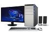
interior and exterior components. Front Panel 9 1 8 7 2 6 3 4 5 No. Component 1 USB 2.0 ports 2 Acer logo 3 Optical drive button 4 Optical drive button (Removable HDD bay for AM551 bezel) 5 Removable HDD bay 6 Power button 7 16 in 1 Card Reader 8 Headphone/Speaker-out/line-out jack - Acer Aspire M5400 | Service Guide - Page 14
Rear Panel 1 14 2 13 3 12 4 5 11 10 6 9 7 8 No. Component 1 Power connector 2 PS2 keyboard port 3 HDMI port 4 VGA port 5 USB 2.0 ports 6 Mic-in 7 Line-out 8 Expansion slot (graphics card and TV tuner card and Mode card) 9 Line-in 10 USB 2.0 ports 11 LAN connector - Acer Aspire M5400 | Service Guide - Page 15
Clock in Sleep State in BIOS Setup is set to Enabled.) BIOS Item Specification BIOS code programer AMI Kernel with Acer skin BIOS version P01-A0 BIOS ROM type SPI ROM BIOS ROM size 8Mb Support protocol SMBIOS(DMI)2.4/DMI2.0 Device Boot Support Support BBS spec 1st priority: HDD 2nd - Acer Aspire M5400 | Service Guide - Page 16
~4GB 1G~16GB System Memory Item Specification Memory slot number 4 slot Support Memory size per socket 1GB/2GB/4GB Support memory type DDRIII Support memory interface DDRIII 1066/1333MHz Support memory voltage 1.5V Support memory module package 240-pin DDRIII Support to parity check - Acer Aspire M5400 | Service Guide - Page 17
Support mode Specification RS880P SATA X 6 RAID/AHCI/IDE mode option USB Port Item Universal HCI USB Class USB Connectors Quantity Specification USB 2.0/1.1 Support random, 1 hour per axis in all 3 axes. Power Management Devices S1 S3 S4 Power Button V V V USB Keyboard/Mouse V V N/A - Acer Aspire M5400 | Service Guide - Page 18
keyboard an mouse for APM mode. • Resume recovery time :7-10sec Suspend Mode • Independent power management timer(2-120minutes,time step=10minute)or pushing • ACPI specification 1.0b • S0,S1,S2 and S5 sleep state support. • On board device power management support. • On board device configuration - Acer Aspire M5400 | Service Guide - Page 19
nonvolatile memory called CMOS RAM. This memory area is not part of the system RAM which allows configuration data to be retained when power is be simply referred to as "BIOS", "Setup", or "Setup utility" in this guide. The screenshots used in this guide display default system values. These values - Acer Aspire M5400 | Service Guide - Page 20
• End - Move the cursor to the last page of a multiple page menu. • + and - keys - Select a value for the currently selected field (only if it is user-configurable). Press these keys repeatedly to display each possible entry, or the Enter key to choose from a pop-up menu. NOTE: Grayed-out fields are - Acer Aspire M5400 | Service Guide - Page 21
following main setup categories. Parameter Product Information Standard CMOS Features Advanced BIOS Features Advanced Chipset Features Integrated Peripherals Power Management Setup PC Health Status Frequency/Voltage Control BIOS Security Features Load Default Setting Save & Exit Setup Exit Without - Acer Aspire M5400 | Service Guide - Page 22
about the system. These entries are for your reference only and are not user-configurable. Parameter Processor Type Processor Speed System Memory Product Name System Serial Number System BIOS Version BIOS Release Date Asset Tag Number Description Type of CPU installed on the system. Speed - Acer Aspire M5400 | Service Guide - Page 23
Standard CMOS Features Parameter System Date System Time Halt On Description Set the date following the weekday-month-day-year format. Set the system time following the hour-minute-second format. Determines whether the system will stop for an error during the POST. Option All, But Keyboard No - Acer Aspire M5400 | Service Guide - Page 24
to access the Removable Device Priority submenu and specify the boot device priority sequence from available removable drives. Selects power on state for Num Lock. On Off Enables or disables BIOS to display error beeps or messages during USB device enumeration. Disabled Enabled 17 Chapter 2 - Acer Aspire M5400 | Service Guide - Page 25
Surround view Description When enabled, this feature allows the OS to reduce power consumption. When disabled, the system operates at maximum CPU speed. Enables to change the setting. Enables or disables ASF Select a Video memory size Select a Frame buffe size Enables or disables Surrande view - Acer Aspire M5400 | Service Guide - Page 26
. Select an operating mode for the onboard SATA. Enables or disables the onboard USB controller. Enables or disables support for legacy USB devices. Enables or disables support for legacy USB devices. Enables or disables the onboard USB controller. select a mode of the onboard graphics Enables - Acer Aspire M5400 | Service Guide - Page 27
Parameter ACPI Suspend Mode Deep power off mode Power On by RTC Alarm Power On by PCIE Devices Power On by PCI Devices Power On by Modem Ring Wake Up by PS/2 KB/ Mouse Wake Up by USB KB/ Mouse Restore On AC Power Loss Description Select an ACPI state. Select the Deep power off Mode Enables or - Acer Aspire M5400 | Service Guide - Page 28
PC Health Status Parameter system Shutdown Temperature Description Select the system Shutdown Temperature CPU Shutdown Temperature Select the system Shutdown Temperature Smart FAN Enables or disables - Acer Aspire M5400 | Service Guide - Page 29
Frequency/Voltage Control Parameter Spread Spectrum Description Enables or disables the reduction of the mainboard's EMI. Note: Remember to disable the Spread Spectrum feature if you are overclocking. A slight jitter can introduce a temporary boost in clock speed causing the overclocked - Acer Aspire M5400 | Service Guide - Page 30
Change Supervisor Password Description Indicates the status of the supervisor password. Indicates the status of the user password. Supervisor password prevents unauthorized access to the BIOS Setup Utility. Press Enter to change the Supervisor password. Setting a supervisor password 1. Use the up - Acer Aspire M5400 | Service Guide - Page 31
Settings The Load Default Settings menu allows you to load the default settings for all BIOS setup parameters. Setup defaults are quite demanding in terms of resources consumption. If you are using low-speed memory chips or other kinds of low-performance components and you choose to load these - Acer Aspire M5400 | Service Guide - Page 32
Save & Exit Setup The Save & Exit Setup menu allows you to save changes made and close the Setup Utility. 25 Chapter 2 - Acer Aspire M5400 | Service Guide - Page 33
Exit Without Saving The Exit Without Saving menu allows you to discard changes made and close the Setup Utility. Chapter 2 26 - Acer Aspire M5400 | Service Guide - Page 34
Chapter 3 System Disassembly This chapter contains step-by-step procedures on how to disassemble the desktop computer for maintenance and troubleshooting. Disassembly Requirements To disassemble the computer, you need the following tools: • Wrist grounding strap and conductive mat for preventing - Acer Aspire M5400 | Service Guide - Page 35
procedure, perform the steps listed below: 1. Turn off the system and all the peripherals connected to it. 2. Unplug the power cord from the power outlets. 3. Unplug the power cord from the system. 4. Unplug all peripheral cables from the system. 5. Place the system unit on a flat, stable surface - Acer Aspire M5400 | Service Guide - Page 36
rear edge of the side panel. 2. Slide the side panel toward the back of the chassis until the tabs on the cover disengage with the slots on the chassis. 3. Lift the side panel away from the server and put it aside for reinstallation later. Chapter 3 29 - Acer Aspire M5400 | Service Guide - Page 37
very hot when the system is on. NEVER touch the heat sink with any metal or with your hands. 1. Disconnect the fan cable from the mainboard. 2. Use a long-nosed screwdriver to loosen the four screws on the heat sink, in the order as shown below. 30 Chapter 3 - Acer Aspire M5400 | Service Guide - Page 38
3. Lift the heat sink fan assembly away from the mainboard. 4. Use an alcohol pad to wipe off the thermal grease from both the heat sink and the processor. Chapter 3 31 - Acer Aspire M5400 | Service Guide - Page 39
Removing the Processor IMPORTANT:Before removing a processor from the mainboard, make sure to create a backup file of all important data. WARNING:The processor becomes very hot when the system is on. Allow it to cool - Acer Aspire M5400 | Service Guide - Page 40
Modules IMPORTANT:Before removing any DIMM from the memory board, make sure to create a backup file of all important data. 1. Press the holding clips on both sides of the DIMM slot outward to release the DIMM(1,2). 2. Gently pull the DIMM upward to pull it away from the M/B(3). 3 1 2 Chapter - Acer Aspire M5400 | Service Guide - Page 41
Removing the VGA Card 1. Release the Slot cover lock. 2. Remove the screw from chassis. 3. Disconnect the power cables from the VGA card. 4. One finger Press the clip and the same time Gently pull the card to remove it from the mainboard. 34 Chapter 3 - Acer Aspire M5400 | Service Guide - Page 42
Removing the Mode Card 1. Gently pull the Mode card to remove it from the mainboard. Chapter 3 35 - Acer Aspire M5400 | Service Guide - Page 43
Removing the Front Bezel 1. Remove the side panel. Refer to the previous section for instructions. 2. Disconnect the LED cable. 3. Release the front bezel from the chassis interior. 4. Pull the bezel away from the chassis. 36 Chapter 3 - Acer Aspire M5400 | Service Guide - Page 44
Removing Rear USB Board 1. Remove USB cable 2. Release the screw of rear usb. 3. Remove the rear usb board. Chapter 3 37 - Acer Aspire M5400 | Service Guide - Page 45
Removing the Hard Disk Drive 1. Disconnect the data and power cables from the rear of the optical drive and the mainboard. 2. Remove the HDD bracket a. Remove the screw that secures the HDD bracket to the ODD bracket. b. Lift the bracket up and turn it over. 38 Chapter 3 - Acer Aspire M5400 | Service Guide - Page 46
3. Remove the HDD module a. Remove the eight screws secure the HDD module to the HDD bracket. b. Slide the HDD out of the bracket. Chapter 3 39 - Acer Aspire M5400 | Service Guide - Page 47
Removing the Optical Drive 1. Disconnect the data and power cables from the rear of the optical drive. 2. Remove screw from the optical drive. 3. Pull the drive out of the drive. 40 Chapter 3 - Acer Aspire M5400 | Service Guide - Page 48
Removing Cables 1. Remove power switch and LED cables from slot of M/B 2. Remove HDD Data and ODD Data cables from slot of M/B. 3. Remove USB1/2/3 cable from M/B. 4. Remove FIO cable and Audio cable from M/B Chapter 3 41 - Acer Aspire M5400 | Service Guide - Page 49
Removing the removable HDD bay 1. Remove the HDD rail 2. Remove the screws that secure the HDD bay. 3. Remove the HDD bay. 42 Chapter 3 - Acer Aspire M5400 | Service Guide - Page 50
Removing the Power Supply 1. Disconnect the 24-pin and 4-pin power supply cables from the mainboard. 2. Remove the four screw that secures the power supply to the chassis. Chapter 3 43 - Acer Aspire M5400 | Service Guide - Page 51
3. Lift the power supply module out of the chassis. 44 Chapter 3 - Acer Aspire M5400 | Service Guide - Page 52
1. Remove the eight screws that secure the mainboard to the chassis. 7 2 4 6 8 1 3 6 Note:Circuit boards >10 cm² has been highlighted with the yellow rectangle as above image shows. Please detach the Circuit boards and - Acer Aspire M5400 | Service Guide - Page 53
3. Punching in IO Shield then you can remove it. 4. Remove the RTC battery. Note:RTC battery has been highlighted with the yellow circle as above image shows.Please detach the RTC battery and follow local regulations for disposal. 46 Chapter 3 - Acer Aspire M5400 | Service Guide - Page 54
Troubleshooting This chapter provides instructions on how to troubleshoot system hardware problems. Hardware Diagnostic Procedure IMPORTANT:The diagnostic tests described in this chapter are only intended to test Acer the diagnostic tests or repeating thesame operation. 3. Refer to "Power System - Acer Aspire M5400 | Service Guide - Page 55
their appropriate connectors. 9. Verify that all components are Acer-qualified and supported. 10. Replace the system covers. 11. Power on the system. 12. If the problem with the system is not evident, you can try viewing the POST messages and BIOS event logs during the system startup. 48 Chapter 4 - Acer Aspire M5400 | Service Guide - Page 56
codes are used by the BIOS to indicate a serious or fatal error to the end user. Beep codes are used when an error occurs before the system video has been initialized. Beep codes will be generated by the system board speaker, commonly referred to as the PC speaker. AMIBIOS displays the checkpoints - Acer Aspire M5400 | Service Guide - Page 57
to memory in right segments. Copies BIOS from ROM to RAM for faster access. Performs main BIOS checksum and updates recovery status accordingly. Both key sequence and OEM specific method is checked to determine if BIOSrecovery is forced. Main BIOS checksum is tested. If BIOS recovery is necessary - Acer Aspire M5400 | Service Guide - Page 58
Checkpoint DA DC E1-E8 ECEE Description Restore CPUID value back into register. Give control to BIOS POST (ExecutePOSTKernel). See POST Code Checkpoints section of document for more information. System is waking from ACPI S3 state. OEM memory detection/configuration error. This range is reserved - Acer Aspire M5400 | Service Guide - Page 59
code gets control when the BIOS determines that a BIOS recovery needs to occur because the user has forced the update or the BIOS checksum is corrupt. The following table describes the type of checkpoints that may occur during the Bootblock recovery portion of the BIOS. NOTE: Checkpoints may differ - Acer Aspire M5400 | Service Guide - Page 60
USB disk to computer that you want to recovery the system BIOS. 2. Power on the system, BIOS recovery will be done. Wait for about 3 minutes the system will reboot automatically after flash update completed successfully. 3. Press "Del" Key to enter BIOS Setup. 4. Choose " Load Default Settings " and - Acer Aspire M5400 | Service Guide - Page 61
Jumper and Connector Information M/B Placement Chapter 5 Chapter 5 54 - Acer Aspire M5400 | Service Guide - Page 62
?13 HBIOS_WP 15 SPDIF_OUT 17 PCI1 19 PCIE_1X Description AM3 938 socket for CPU CPU fan power header GPIO connector SATA data transfe connector Card reader USB headers SYS fan header BIOS write protect header SPDIF out header PCI socket PCIE_1x socket No Label 2 PWR2 4 DIMM 6 PWR1 - Acer Aspire M5400 | Service Guide - Page 63
set jumper for correct configuration of the mainboard. Setting Jumper Use the motherboard jumpers to set system configuration options. Jumpers Function CPU FAN HEADER Definition 1: SENSE 2: POWER 3: GND SYS_FAN (3 PIN) SYS FAN HEADER 1: SENSE 2: POWER 3: GND CLR_CMOS (3 PIN) Yellow is symbol - Acer Aspire M5400 | Service Guide - Page 64
Jumper/Header Name OBR Function System Recover HEADER Definition 1:SYS_RECOVER 2: GND F_USB1, F_USB2, F_USB3, F_USB4 Yellow is symbol, Red is Pin 1 of symbol. FRONT USB HEADER (2X5) 1. VCC5 2. VCC5 3. D14. D05. D1+ 6. D0+ 7. GND 8. GND 9. KEY 10. GND Yellow is symbol, Red is Pin 1 of symbol. - Acer Aspire M5400 | Service Guide - Page 65
Jumper/Header Name F_1394 F_PANEL Function FRONT 1394 HEADER Yellow is symbol, Red is Pin 1 of symbol. Front panel header Definition 1. 1394_TPA0P_C 2. 1394_TPA0N_C 3. GND 4. GND 5. 1394_TPB0P_C 6. 1394_TPB0N_C 7. 1394_POW_CON_A 8. 1394_POW_CON_A 9. KEY 10. GND 1: HDD+ (PU 5V_S0) 2: PWRLED_PN2(PU - Acer Aspire M5400 | Service Guide - Page 66
Jumper/Header Name LPT SPEAKER Function Printer Header Yellow is symbol, Red is Pin 1 of symbol. Audio internal speaker header Definition 1: STRBJ 2: AFDJ 3: PRP_D0 4: PRERRJ 5:PRP_D1 6: INITJ 7: PRP_D2 8: SLINJ 9: PRP_D3 10: GND 11: PRP_D4 12: GND 13: PRP_D5 14: GND 15: PRP_D6 16: GND 17: PRP_D7 - Acer Aspire M5400 | Service Guide - Page 67
Jumper/Header Name SPDIF_OUT, SPDIF_OUT1 Function Definition 1: VCC (5V_SYS) 2: KEY 3: A_SPDIF_OUT1 4: GND COM2 COM2 1 2 3 4 5 6 7 8 9 X Header_2X5_K10 @Commercial Yellow is symbol, Red is Pin 1 of symbol. Yellow is symbol, Red is Pin 1 of symbol. 1. JDCD2J 2. JSIN2 3. JSOUT2 4. - Acer Aspire M5400 | Service Guide - Page 68
USB CONNECTORS (Stacked)(Black) USB_X4 Pin "11,21,31,41" 12 13 14 22 23 24 32 33 34 42 43 44 "45,46,47,48, 49,50" Signal Name VCC_USB1 USBP3N_R USBP3P_R Ground USBP2N_R USBP2P_R Ground USBP5N_R USBP5P_R Ground USBP4N_R USBP4P_R Ground Ground 61 Chapter 5 - Acer Aspire M5400 | Service Guide - Page 69
11.2.2LAN-USB_X2 Pin "1, 5" 2 3 "4, 8" 6 7 "23,24,25,26, 27,28,29,30" 9 10 11 12 13 14 15 16 17 18 19 20 21 22 Signal Name VCC_USB0 (5V) USBP7N_R USBP6N_R GND USBP6N_R USBP6P_R Ground AVDD18 MDI0+ MDI0MDI1+ MDI1MDI2+ MDI2MDI3+ MDI3GND ACT_LED LAN_LINK_LED 100_LED 1G_LED NOTE: Pins 9-18 for RJ-45 - Acer Aspire M5400 | Service Guide - Page 70
Audio Back Panel Connectors AUDIO1A (MIC) Pin 1 2 3 4 5 Signal Name GND_AUDIO A_MIC1_L A_MIC1_JD GND_AUDIO A_MIC1_R AUDIO1B (Line in) Pin 31 32 33 34 35 Signal Name GND_AUDIO A_LOUT_L A_LOUT_JD GND_AUDIO A_LOUT_R AUDIO1C (Line out) Pin 21 22 23 24 25 Signal Name GND_AUDIO A_LINE1_L A_LINE1_JD - Acer Aspire M5400 | Service Guide - Page 71
PIDE_CS3J Ground VGA Pin 1 2 3 4 5 6 7 8 9 10 11 12 13 14 15 Signal Name R G B ID0 GND GND GND GND NC (5V_VGA) GND ID1 SDA HSYNC VSYNC SCL HDMI Pin 1 2 Signal Name HDMI_TXDP2_C GND Chapter 5 64 - Acer Aspire M5400 | Service Guide - Page 72
Pin 3 4 5 6 7 8 9 10 11 12 13 14 15 16 17 18 19 20 21 DVI-D Pin 1 2 3 4 5 6 7 8 9 10 11 12 PS2 Pin 1 2 3 4 5 6 65 Signal Name HDMI_TXDN2_C HDMI_TXDP1_C GND HDMI_TXDN1_C HDMI_TXDP0_C GND HDMI_TXDN0_C HDMI_TXCP_C GND HDMI_TXCN_C NC NC HDMI_DDCCLK_C HDMI_DDCDATA_C GND 5V_HDMI_C HP_DET_C GND GND - Acer Aspire M5400 | Service Guide - Page 73
Pin 7 8 9 COM Pin 1 2 3 4 5,10,11 6 7 8 9 Signal Name MS_DA NC GND Signal Name JDCD1J JSIN1 JSOUT1 JDTR1J GND JDSR1J JRTS1J JCTS1J JRI1J Pin 16 17 Signal Name GND GND Chapter 5 66 - Acer Aspire M5400 | Service Guide - Page 74
(Field Replaceable Unit) list in global configuration of the Aspire M5400(G) desktop computer. Refer to this chapter whenever ordering the parts to , it will NOT be noted on the printed Service Guide. For Acer authorized service providers, your Acer office may have a different part number code from - Acer Aspire M5400 | Service Guide - Page 75
Aspire M5400(G) Exploded Diagram(AM551 ASSY) NOTE: This section will be updated when more information becomes available. ITEM 1 2 3 4 NAME CHASSIS ASM TOP-COVER ODD REMOVABLE HDD CARRIER Q'TY 1 1 1 2 ITEM 5 6 7 8 NAME FRONT BEZEL HDD COVER SIDE COVER POWER Q'TY 1 1 1 1 68 Chapter 6 - Acer Aspire M5400 | Service Guide - Page 76
Aspire M5400(G) Exploded Diagram(AM550 ASSY) NOTE: This section will be updated when more information becomes available. ITEM 1 2 3 4 NAME CHASSIS ASM TOP-COVER ODD REMOVABLE HDD CARRIER Q'TY 1 1 1 2 ITEM 5 6 7 8 NAME FRONT BEZEL HDD COVER SIDE COVER POWER Q'TY 1 1 1 1 Chapter 6 69 - Acer Aspire M5400 | Service Guide - Page 77
Aspire M5400(G) FRU List MB Kit Category Part Number Mainboard FRS880F consumer Mainboard FRS880F consumer Support 140W CPU Acer P/N MB.SE109.001 MB.SE109.003 IO Shielding Chassis Bezel CPU Cooler System Fan CPU 70 Rear I/O Shielding for MB Micro-Tower chassis HM090H for - Acer Aspire M5400 | Service Guide - Page 78
Category Memory Chapter 6 Part Number AMD Phenom II 555 AMD Phenom II 550 AMD Phenom 1333MHz 2GB DDRIII 1333MHz 2GB DDRIII 1333MHz 2GB DDRIII 1333MHz 4GB DDRIII 1333MHz 4GB DDRIII 1333MHz 4GB DDRIII 1333MHz 4GB Acer P/N KC.PH202.555 KC.PM202.550 KC.PH202.B55 KC.AM202.640 KC.AM202.635 KC.AE202.605 - Acer Aspire M5400 | Service Guide - Page 79
Category HDD ODD 72 Part Number Acer P/N HDD HGST 3.5" 7200rpm 160GB HDT721016SLA380 Saturn SATA II LF F/W:31B HDD HGST 3.5" 7200rpm 160GB Jupiter HDD HGST 3.5" 7200rpm 320GB HDT721032SLA380 Saturn SATA II LF F/W:31B - Acer Aspire M5400 | Service Guide - Page 80
HF +Win7 ODD HLDS BD RW HH 6X BH20F Black Bezel SATA (Win7 FW) Acer P/N KU.01601.007 KV.0040F.002 KO.0060D.005 KO.0060F.002 KU.0060D VGA DVI HDMI ATX BRACKET ROHS HD5750 1GB GDDR 5 (128BITS) HYNIX DVI DVI HDMI DP W/ATX BKT ROHS 288-1E160-000AC HD5750 1GB GDDR 5 (128BITS) SAMSUNG DVI HDMI VGA W/ATX - Acer Aspire M5400 | Service Guide - Page 81
HDMI VGA W/ATX BKT ROHS 288-1E145-101AC HD5450 512MB SDDR 3 (64BITS) HYNIX DVI HDMI VGA W/ATX BKT ROHS AMD RADEON HD5450 512MB (64BIT) DDR3 DVI HDMI VGA ATX BRACKET ROHS Acer V.92 - Pinball (P40) FX.10100.004 WLAN 74 WN7600R, WLAN PCI-Ex1 card 802.11 b/g/n 1T x 2R, Ralink 1T x 2R, - Acer Aspire M5400 | Service Guide - Page 82
Category Power Supply Mouse Speaker Remote control Chapter 6 Part Number Acer P/N Non-PFC 250W (30L) EuP Non-PFC 250W (30L) EuP MS.11200.017 MS.11200.018 MS.11200.048 MS.11200.015 RV.11000.010 Neosonica Speaker Acer logo /LF /0810 / 9M-20A200-000 Neosonica Speaker USB with new color AC-MT-018 - Acer Aspire M5400 | Service Guide - Page 83
Number SMK Remote Controller Japan RRS9003-3407EC Quatro Pulse Acer P/N RT.11300.026 Keyboard CHICONY KG-0766 RF2.4 Standard 104KS Black US w/o Aspire logo Keyboard CHICONY KG-0766 RF2.4 Standard 104KS Black Traditional Chinese w/o Aspire logo Keyboard CHICONY KG-0766 RF2.4 Standard 104KS Black - Acer Aspire M5400 | Service Guide - Page 84
logo Keyboard CHICONY KG-0766 RF2.4 Standard 105KS Black Kazakh w/o Aspire logo Keyboard CHICONY KG-0766 RF2.4 Standard 104KS Black Turkmen w/o Aspire logo Keyboard CHICONY KG-0766 RF2.4 Standard 109KS Japanese with J1 layout Acer P/N KB.RF403.083 KB.RF403.084 KB.RF403.085 KB.RF403.086 KB.RF403 - Acer Aspire M5400 | Service Guide - Page 85
/2 Standard 105KS Black Slovak w/o eKey Keyboard CHICONY KB-0759 PS/2 Standard 104KS Black Russian w/o eKey Keyboard CHICONY KB-0759 PS/2 Standard 105KS Black Hungarian w/o eKey Acer P/N KB.PS203.287 KB.PS203.288 KB.PS203.289 KB.PS203.290 KB.PS203.291 KB.PS203.292 KB.PS203.293 KB.PS203.295 KB - Acer Aspire M5400 | Service Guide - Page 86
w/o eKey , w/i farmer PC label Keyboard CHICONY KB-0759 PS/2 Standard 104KS Black US w/o eKey , w/i farmer PC label Keyboard CHICONY KB-0759 Thailand w/o eKey Keyboard LITE-ON SK-9620 PS/2 Standard 105KS Black Spanish w/o eKey Acer P/N KB.PS203.311 KB.PS203.312 KB.PS203.313 KB.PS203.314 KB.PS203.315 - Acer Aspire M5400 | Service Guide - Page 87
Black Danish w/o eKey Keyboard LITE-ON SK-9620 PS/2 Standard 104KS Black Czech w/o eKey Keyboard LITE-ON SK-9620 PS/2 Standard 105KS Black Romanian w/o eKey Acer P/N KB.PS20B.076 KB.PS20B.077 KB.PS20B.078 KB.PS20B.080 KB.PS20B.081 KB.PS20B.082 KB.PS20B.083 KB.PS20B.084 KB - Acer Aspire M5400 | Service Guide - Page 88
107KS Black Brazilian Portuguese w/o eKey Keyboard CHICONY KU-0760 USB Standard 109KS Black Japanese w/o eKey Keyboard CHICONY KU-0760 USB Standard 105KS Black German w/o eKey Acer P/N KB.PS20B.100 KB.PS20B.101 KB.PS20B.102 KB.PS20B.103 KB.PS20B.104 KB.PS20B.105 KB.PS20B.106 KB.PS20B.108 KB - Acer Aspire M5400 | Service Guide - Page 89
Black Spanish Latin w/o eKey Keyboard CHICONY KU-0760 USB Standard 105KS Black Turkish-Q w/o eKey Keyboard CHICONY KU-0760 USB Standard 105KS Black Arabic/French w/o eKey Acer P/N KB.USB03.204 KB.USB03.205 KB.USB03.206 KB.USB03.207 KB.USB03.208 KB.USB03.209 KB.USB03.210 KB.USB03.211 KB - Acer Aspire M5400 | Service Guide - Page 90
Standard 104KS Black US w/o eKey; w/i farmer PC label Keyboard CHICONY KU-0760 USB Standard 105KS Black English/Canadian French Keyboard CHICONY KU-0760 USB Standard 105KS Black Czech/Slovak Keyboard CHICONY KU-0760 USB Standard 109KS Japanese with J1 layout Acer P/N KB.USB03.227 KB.USB03.228 KB - Acer Aspire M5400 | Service Guide - Page 91
Arabic/French w/o eKey Keyboard LITE-ON SK-9625 USB Standard 104KS Black Kazakh w/o eKey Keyboard LITE-ON SK-9625 USB Standard 104KS Black Turkmen w/o eKey Acer P/N KB.USB0B.172 KB.USB0B.173 KB.USB0B.174 KB.USB0B.175 KB.USB0B.176 KB.USB0B.177 KB.USB0B.178 KB.USB0B.179 KB - Acer Aspire M5400 | Service Guide - Page 92
English/Canadian French Keyboard LITE-ON SK-9625 USB Standard 105KS Black Macedonian Keyboard LITE-ON SK-9625 USB Standard 109KS Japanese with J1 layout Acer P/N KB.USB0B.195 KB.USB0B.196 KB.USB0B.198 KB.USB0B.202 KB.USB0B.199 Keyboard LITE-ON SK-9625S USB Standard 104KS Black US - Acer Aspire M5400 | Service Guide - Page 93
Czech/Slovak with new color AC-MT-018 Keyboard LITE-ON SK-9625S USB Standard 109KS Japanese with J1 layout & new color AC-MT-018 Acer P/N KB.USB0B.100 KB.USB0B.101 KB.USB0B.102 KB.USB0B.103 KB.USB0B.104 KB.USB0B.105 KB.USB0B.106 KB.USB0B.107 KB - Acer Aspire M5400 | Service Guide - Page 94
CHICONY KG-0766 RF2.4 Standard 105KS Black Polish with new silver color Keyboard CHICONY KG-0766 RF2.4 Standard 105KS Black Slovenian with new silver color Acer P/N KB.RF403.135 KB.RF403.136 KB.RF403.137 KB.RF403.138 KB.RF403.139 KB.RF403.140 KB.RF403.141 KB.RF403.142 KB - Acer Aspire M5400 | Service Guide - Page 95
CHICONY KG-0766 RF2.4 Standard 105KS Czech/Slovak with new silver color Keyboard CHICONY KG-0766 RF2.4 Standard 109KS Japanese with J1 layout & silver color Acer P/N KB.RF403.159 KB.RF403.160 KB.RF403.161 KB.RF403.162 KB.RF403.163 KB.RF403.164 KB.RF403.165 KB.RF403.166 KB