Acer Aspire M7720 Aspire M7720 Service Guide
Acer Aspire M7720 Manual
 |
View all Acer Aspire M7720 manuals
Add to My Manuals
Save this manual to your list of manuals |
Acer Aspire M7720 manual content summary:
- Acer Aspire M7720 | Aspire M7720 Service Guide - Page 1
Aspire ASM7720 Service Guide Service guide files and updates are available on the AIPG/CSD web; for more information please refer to http://csd.acer.com.tw PRINTED IN TAIWAN 1 - Acer Aspire M7720 | Aspire M7720 Service Guide - Page 2
Revision History Please refer to the table below for the updates made on aBulldog ASM7720 Service Guide. Date Chapter Updates 2 - Acer Aspire M7720 | Aspire M7720 Service Guide - Page 3
, manual or otherwise, without the prior written permission of Acer Incorporated Disclaimer The information in this guide is subject to change without notice. Acer Incorporated makes no representations or warranties, either expressed or implied, with respect to the contents hereof and specifically - Acer Aspire M7720 | Aspire M7720 Service Guide - Page 4
to the current topic. WARNING Alerts you to any damage that might result from doing or not doing specific actions. CAUTION Gives precautionary measures to avoid possible hardware or software problems. IMPORTANT Remind you to do specific actions relevant to the accomplishment of procedures. IV - Acer Aspire M7720 | Aspire M7720 Service Guide - Page 5
supports, please read the following general information. 1. This Service Guide provides you with all technical information relating to the BASIC CONFIGURATION decided for Acer modem, or extra memory capability). These LOCALIZED FEATURES will NOT be covered in this generic service guide. In such cases - Acer Aspire M7720 | Aspire M7720 Service Guide - Page 6
Panel 8 Hardware Specifications and Configurations 9 Power Management Function (ACPI support function 16 Chapter 2 System Utilities 17 Entering Setup 18 Product Information 20 Standard CMOS Features 21 Advanced BIOS Features 23 Integrated Peripherals 25 Power Management 27 PC Health Status - Acer Aspire M7720 | Aspire M7720 Service Guide - Page 7
Specifications Features Operating System … Microsoft Windows Vista Premium 64-bit Processor … Socket Type: Intel® Socket T LGA 1366 pin … Processor Type: … Intel Bloomfield i7 CPUs … FSB 1600 MHz CPUs Chipset … Intel X58 + ICH10R PCB … Form Factor: Micro ATX … Dimension/Layer: 244mm x244mm Memory - Acer Aspire M7720 | Aspire M7720 Service Guide - Page 8
audio codec … Audio Channel: 7.1 channel … Audio Controller /Codec: ALC888S-VE 7.1 … Connectors support: … Rear 6 jack follow HD audio definition, … Audio jacks color coding: should meet Microsoft Windows Logo Program Device Requirements: Audio-0002 … 1 front panel audio header (2*5) … S/N ratio: 90 - Acer Aspire M7720 | Aspire M7720 Service Guide - Page 9
be built in with default and RPL function is optional by service BIOS) … BIOS shall auto detect FDD to avoid checksum error when boot I/O Connector … Controller: Super I/O ITE8720 (F stepping or after; must full support Intel platform) Rear I/O Connector … 1 PS/2 Keyboard port, … 1 PS/2 Mouse port - Acer Aspire M7720 | Aspire M7720 Service Guide - Page 10
… 1 CPU socket … 6 DDR-3 memory sockets … 2 PCI Express x16 slot … 1 PCI Express x 4 slots … 1 PCI Express x 1 slots … 6 SATA connectors(Need to confirm no interfere with gfx card) … 3 2*5 pin Intel FPIO specification USB pin connectors (follow Intel FPIO standard Specification) … 1 2*5 pin - Acer Aspire M7720 | Aspire M7720 Service Guide - Page 11
capability) … Demand for both PFC/Non-PFC solutions (two different quotations are needed) … Minimum 6 Serial ATA power connector solution should be included (by default) … Minimum 3 6-pin graphic card connector included … Minimum 2 big 4-pin power connector included … Full Range PSU … PS2 style 5 - Acer Aspire M7720 | Aspire M7720 Service Guide - Page 12
Block Diagram 6 - Acer Aspire M7720 | Aspire M7720 Service Guide - Page 13
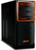
Aspire ASM7720 Front Panel The computer's front panel consists of the following: Label 1 2 3 4 5 6 Description Media Control Center Optical drive Speaker /Microphone jack Gateway Logo Card reader Power button 7 - Acer Aspire M7720 | Aspire M7720 Service Guide - Page 14
4 7 Label Description 1 Voltage selector switch 2 Power card socket 3 PS/2 keyboard connecter 4 Serial port 5 ESATA port 6 USB 2.0 connector 7 Audio connector 8 9 10 11 12 13 Label Description 8 Fan aperture 9 PS/2 mouse connecter 10 System FAN 11 1394 connector 12 LAN - Acer Aspire M7720 | Aspire M7720 Service Guide - Page 15
(If Stop CPU Clock in Sleep State in BIOS Setup is set to Enabled.) BIOS Item BIOS code programmer BIOS version BIOS ROM type BIOS ROM size Support protocol Device Boot Support Support to LS-120 drive Support to BIOS boot block feature Specification Phoenix Award or AMI Kernel with Acer skin R01 - Acer Aspire M7720 | Aspire M7720 Service Guide - Page 16
Setup Utility Press while the system is booting to enter BIOS Setup Utility. Main Board Major Chips Item Specification North Bridge South Bridge APG controller Super I/O controller Audio controller LAN controller -lay with ALC888) Intel 82567LF Boazman Gbe Ethernet LAN PHY ICH 10R ITE 8720 10 - Acer Aspire M7720 | Aspire M7720 Service Guide - Page 17
System Memory Supported System Memory Total Memory 1GB ~2GB 1GB ~2GB 1GB ~2GB 1GB ~2GB 1GB ~2GB 1GB ~2GB 1GB ~12GB Item Specification Memory slot number Support Memory size per socket Support memory type Support memory interface Support memory voltage Support memory module package Support to - Acer Aspire M7720 | Aspire M7720 Service Guide - Page 18
Sampling rate MPU-401 UART support Microphone jack Headphone jack Specification Intel ICH 10R ALC888S-VE codec 7.1 Enable/disable by BIOS Setup Stereo Sound Blaster Pro Integrated dual game port Meets AC'97and WHQL specifications Yes, internal FM synthesizer 48 KHz (max.) Yes Supported Supported 12 - Acer Aspire M7720 | Aspire M7720 Service Guide - Page 19
SATA controller SATA controller resident bus Number of SATA channel Support bootable CD-ROM Specification Intel ICH 10R PCI bus SATA X 6 YES USB Port Item Universal HCI USB Class USB Connectors Quantity Specification USB 2.0/1.1 Support legacy keyboard for legacy mode 6 back panel ports 4 ports - Acer Aspire M7720 | Aspire M7720 Service Guide - Page 20
Environmental Requirements Item Specification Temperature Operating Non-operating +5°C ~ +35°C -20 ~ +60°C (Storage package) Humidity Operating Non-operating 15% to 80% RH 10% to 90% RH Vibration Operating (unpacked) 5 ~ 500 Hz: 2.20g RMS random, 10 minutes per axis in all 3 axes 5 ~500 - Acer Aspire M7720 | Aspire M7720 Service Guide - Page 21
S4 S5 Power Button V V V V USB V V N/A N/A Keyboard/Mouse PME Disabled Disabled Disabled Disabled RCT Disabled Disabled Disabled Disabled WOR Disabled Disabled Disabled Disabled … Devices wake up from S3 should be less than … Devices wake up from S5 should be less than 10 seconds - Acer Aspire M7720 | Aspire M7720 Service Guide - Page 22
16 - Acer Aspire M7720 | Aspire M7720 Service Guide - Page 23
the computer unless you get a Run Setup message. The Setup program loads configuration values into the battery-backed nonvolatile memory called CMOS RAM. This memory area is not part of the system RAM. NOTE: If you repeatedly receive Run Setup messages, the battery may be bad/flat. In this case, the - Acer Aspire M7720 | Aspire M7720 Service Guide - Page 24
the computer and the system will start POST (Power On Self Test) process. When the message of "Press DEL to enter SETUP" CMOS Features Advance BIOS Features CMOS Advanced Chipset Features Integrated Peripherals Power Management Setup PC Health Status Frequency/VoltageControl BIOS Security Features - Acer Aspire M7720 | Aspire M7720 Service Guide - Page 25
board This setup page includes all the items in standard compatible BIOS This setup page includes all the items of Award special enhanced Integrated Peripherals This setup page includes all onboard peripherals Power Management Setup PC Health Status Frequency/Voltage Control This setup page - Acer Aspire M7720 | Aspire M7720 Service Guide - Page 26
. Product Information Processor Type : Intel(R) Core(TM)2 i7 CPU 920 ﹫2.67GHz Processor Speed : 2.66GHz System Memory : 4047MB System Manufacture : Acer Product Name : Asprie M7720 System Serial Number : System BIOS Version : R01-A1 BIOS Release Date : 10/28/2008 Asset Tag Number - Acer Aspire M7720 | Aspire M7720 Service Guide - Page 27
Help 8AHCI Port0 8AHCI Port1 8AHCI Port2 8AHCI Port3 8AHCI Port4 8AHCI Port5 [Not Detected] [Not Detected] [Not Detected] [ATAPI CDROM] [Not Detected] [Hard Disk] Use [ENTER], [TAB] or [SHIFT-TAB] to select A field . Use [+] or [-] to configure system Time. Halt on Setting [All, But Keyboard - Acer Aspire M7720 | Aspire M7720 Service Guide - Page 28
the time following the hour-minute-second format This item enables use to select the situation if the BIOS stops the POST process and the notification Options Week: From [Sun.] to [Sat.]. determined by BIOS and is display only Day: from [1] to [31] (or the maximum allowed in the month. Year: from - Acer Aspire M7720 | Aspire M7720 Service Guide - Page 29
tests while [Enabled], booting. This will decrease the time needed [Disabled] to boot the system The item allows you to see the sequence of boot device where BIOS attempts to load the disk operation system. Specifies the boot device. Priority sequence from available Hard Drives Select Power - Acer Aspire M7720 | Aspire M7720 Service Guide - Page 30
Advanced Chipset Setup CMOS Setup Utiliyt - Copyright (c) 1985-2008,American Megatrends, Inc Advanced Chipset Features Intel EIST Intel XD Bit Intel VT Intel VT-d Enabled Enabled Enabled Enabled Item Help Disable: Disable GV3 Enable: Enable GV3 KLIJ: Move Enter: Select F1: General Help +/-/: - Acer Aspire M7720 | Aspire M7720 Service Guide - Page 31
- Copyright (c) 1985-2008, American Megatrends, Inc. Integrated Peripherals Onboard SATA Mode Onboard ESATA Controller Onboard USB Controller Legacy USB Support Onboard LAN Controller Onboard LAN Option ROM Onboard Audio Controller Onboard 1394 Controller Serial Port1 Address [AHCI] [AHCI Mode - Acer Aspire M7720 | Aspire M7720 Service Guide - Page 32
Onboard SATA Mode Onboard ESATA Mode Onboard USB Controller Legacy USB Support Onboard Audio Controller Onboard LAN Controller Onboard LAN Option ROM This item is only available when onboard LAN controller is enabled Allows BIOS to select serial port1 base addresses Options AHCI Disabled / AHCI - Acer Aspire M7720 | Aspire M7720 Service Guide - Page 33
Wake Up by USB KB//Mouse Restore On AC Power Loss [Yes] [S3 (STR)] [Disabled] [Disabled] [Disabled] [Disabled] [Enabled] [Enabled] [Last State] Item Help Yes/ No ACPI support for Operating System. Yes: If OS supports ACPI. No: If OS does not support ACPI. KLIJ: Move Enter: Select F1: General Help - Acer Aspire M7720 | Aspire M7720 Service Guide - Page 34
Status CMOS Setup Utiliyt - Copyright (c) 1985-2008,American Megatrends, Inc. PC Health Status CPU Temperature (PECI Mode) System Temperature CPU Fan Speed System Fan Speed CPU Core +1.1V +3.30V +5.00V +12.0V 5VSB : 35℃/95℉ : 46℃/114℉ : 1383 RPM : 1046 RPM : 1.120V : 1.152V : 3.277V : 4.924V - Acer Aspire M7720 | Aspire M7720 Service Guide - Page 35
Frequency/Voltage Control CMOS Setup Utiliyt - Copyright (c) 1985-2008,American Megatrends, Inc Frequency/Voltage Control Spread Spectrum Enabled Item Help Spread spectrum modulation KLIJ: Move Enter: Select F1: General Help +/-/: Value F10: Save ESC: Exit F9: Optimized Defaults The - Acer Aspire M7720 | Aspire M7720 Service Guide - Page 36
Features CMOS Setup Utiliyt - Copyright (c) 1985-2008,American Megatrends, Inc. BIOS Security Features Supervisor Password User Password Change Supervisor Password : Not installed : Not Installed [Press Enter] Item Help Install or Change the Password KLIJ: Move Enter: - Acer Aspire M7720 | Aspire M7720 Service Guide - Page 37
PC Health Status Standard CMOS Features Frequency/Voltage Control Advance BIOS Features CMOS Load Default Settings? BIOS Security Features Advanced Chipset Features BIOS LLooaabbDDeefafauultltSeStetitntignsgs Integrated Peripherals Power the factory defaults for BIOS and Chipset Features, which - Acer Aspire M7720 | Aspire M7720 Service Guide - Page 38
Save & Exit Setup Highlight this item and press to save the changes that you have made in the Setup Utility and exit the Setup Utility. The following table describes the parameters found in this menu: Parameter Save & Exit Setup Description Press to save the changes that have made - Acer Aspire M7720 | Aspire M7720 Service Guide - Page 39
Exit Without Saving Highlight this item and press to discard any changes that you have made in the Setup Utility and exit the Setup Utility. Parameter Exit Without Saving Description Press to discard any changes and exit the Setup Utility Options 33 - Acer Aspire M7720 | Aspire M7720 Service Guide - Page 40
Chapter 3 Machine Disassembly and Replacement To disassemble the computer, you need the following tools: Wrist grounding strap and conductive mat for preventing electrostatic discharge. Wire cutter. Phillips screwdriver (may require different size). NOTE: The screws for the different components vary - Acer Aspire M7720 | Aspire M7720 Service Guide - Page 41
General Information Before You Begin Before proceeding with the disassembly procedure, make sure that you do the following: 1. Turn off the power to the system and all peripherals. 2. Unplug the AC adapter and all power and signal cables from the system 35 - Acer Aspire M7720 | Aspire M7720 Service Guide - Page 42
Disassembly Procedure This section tells you how to disassemble the system when you need to perform system service. Please also refer to the disassembly video, if available. CAUTION: Before you proceed, make sure you have turned off the system and all peripherals connected to it. 36 - Acer Aspire M7720 | Aspire M7720 Service Guide - Page 43
ASM7720 Standard Disassembly Process Bezel Process: 1. According to the requirement, paste ATI, OS, CPU, HDMI and marketing label by SKU. Remove side cover Process: 1. Put the Computer on the worktable lightly. 2. Release left/right side cover with 4 screws then remove left/right side cover. 37 - Acer Aspire M7720 | Aspire M7720 Service Guide - Page 44
Screw location Screw location Remove CPU fan pipe Process: 1. Release the CPU fan pipe. 2 3 1 4 38 - Acer Aspire M7720 | Aspire M7720 Service Guide - Page 45
Remove Cards Process: 1. Release the slot cover tooless 2. Remove VGA ﹑TV﹑Modem Card,the following list is for your reference about the mutual location relation (Optional by SKU). 39 - Acer Aspire M7720 | Aspire M7720 Service Guide - Page 46
Remove HDD Data Cables Process: 1. Remove master HDD data cable from M/B SATA1/SATA3(Optional by SKU). 2. Remove slave ODD data cable from M/B SATA2/SATA4(Optional by SKU) 40 - Acer Aspire M7720 | Aspire M7720 Service Guide - Page 47
Remove slave HDD cable Remove master HDD cable Remove ODD DATA cable Process: 1. Remove master ODD data/power cable from Master ODD. 41 - Acer Aspire M7720 | Aspire M7720 Service Guide - Page 48
HDD data cable from master HDD. 2. Remove slave HDD data cable from slave HDD. Remove Cables Process: 1. Remove Power SW cable cable from M/B. 2. Remove FI/O USB cable from M/B. 3. Remove MCR USB cable from M/B. 4. Remove Card reader cable from M/B. 5. Remove audio cable from the "AUDIO" port on - Acer Aspire M7720 | Aspire M7720 Service Guide - Page 49
Remove HDD Process: 1. Remove the screws and take out HDD bracket . 2. Remove two sides with 2 screws for each and then remove the master HDD and Slave HDD. 3. Remove Slave HDD from the second HDD location. (Optional by SKU) 43 - Acer Aspire M7720 | Aspire M7720 Service Guide - Page 50
Master HDD location 2 1 Slave HDD location 4 3 Remove ODD Process: 1. Remove bezel of chassis. 2. Remove Master ODD from the location. 3. Remove slave ODD from the location. (Optional by SKU) 44 - Acer Aspire M7720 | Aspire M7720 Service Guide - Page 51
Remove Cables Process: 1. Remove M/B power cable from M/B "ATX1". 2. Remove 12 V power cable from M/B" JPW1" 3. Remove System Fan cable from M/B"SYS-F2". M/B power cable 45 - Acer Aspire M7720 | Aspire M7720 Service Guide - Page 52
12V CPU Power cable SYS_FAN port Remove System FAN Process: 1. Release four screws according to the following picture. 2. Remove Sys Release four screws. FAN (Optional by SKU) 4 1 2 3 46 - Acer Aspire M7720 | Aspire M7720 Service Guide - Page 53
Remove mother board Process: 1. Release 8 pcs screws form the corresponding hole. 2. Release screws according to the following picture in turn. 3. Remove the Mother board from chassis. 47 - Acer Aspire M7720 | Aspire M7720 Service Guide - Page 54
Remove CPU cooler Process: 1. Remove cooler power cable from M/B "CPU-F2". 2. Release screw 1 first, then fixes screw 2, screw 3 & screw 4 (As Picture). Remove Cooler from the Retention module. Remove memory Process: 1. Remove the first Memory from DIMM. 2. Remove the second Memory from DIMM2 ( - Acer Aspire M7720 | Aspire M7720 Service Guide - Page 55
Remove CPU Process: 1. Remove CPU according following the pictures. Lock the Handle Remove I/O shielding Process: 1. Remove I/O Shielding. 49 - Acer Aspire M7720 | Aspire M7720 Service Guide - Page 56
50 - Acer Aspire M7720 | Aspire M7720 Service Guide - Page 57
Chapter 4 Troubleshooting Please refer to generic troubleshooting guide for troubleshooting information relating to following topics: … Power-On Self-Test (POST) … POST Check Points … POST Error Messages List … Error Symptoms List 51 - Acer Aspire M7720 | Aspire M7720 Service Guide - Page 58
Chapter 5 52 - Acer Aspire M7720 | Aspire M7720 Service Guide - Page 59
53 - Acer Aspire M7720 | Aspire M7720 Service Guide - Page 60
ATX_POWER: ATX 24-pin Power Connector 1 2 3 4 5 6 7 8 9 10 11 12 13 14 15 16 17 18 19 20 21 22 23 24 Pin 1 2 3 4 5 6 7 8 9 10 11 12 Signal Name +3.3 +3.3 COM +5V COM +5V COM PWR OK 5VSB +12V +12V +3.3V Pin 13 14 15 16 17 18 19 20 21 - Acer Aspire M7720 | Aspire M7720 Service Guide - Page 61
55 - Acer Aspire M7720 | Aspire M7720 Service Guide - Page 62
56 - Acer Aspire M7720 | Aspire M7720 Service Guide - Page 63
the FRU (Field Replaceable Unit) listing in global configurations of Aspire ASM7720. Refer to this chapter whenever ordering for parts to repair made, it will not be noted in the printed Service Guide. For ACER-AUTHORIZED SERVICE PROVIDERS, your Acer office may have a DIFFERENT part number code to - Acer Aspire M7720 | Aspire M7720 Service Guide - Page 64
4 5 6 7 8 9 10 11 12 13 DESCRIPTION TOP PLASTIC 1-TOP-PLATE SCREW CARD READ ASSY MCI ASSY GEAR-BKT POWER SWITCHWITH CABLE GEAR(PG-08A-45W) STANDOFF-A BASE BEZEL FOR ACER RUBBER-FOOT(FRONT) SCREW RUBBER-FOOT(BACK) GLIP CLAMP CHF-B-3M PLT,BK,I/O,EVT 2-PCI-SHIELD 1-BACK CPU CLAMP FW-IDL-NOW LITEON