Acer Aspire Z1620 Acer Aspire Z1620 Desktop Service Guide
Acer Aspire Z1620 Manual
 |
View all Acer Aspire Z1620 manuals
Add to My Manuals
Save this manual to your list of manuals |
Acer Aspire Z1620 manual content summary:
- Acer Aspire Z1620 | Acer Aspire Z1620 Desktop Service Guide - Page 1
Aspire Z1620 - Acer Aspire Z1620 | Acer Aspire Z1620 Desktop Service Guide - Page 2
guide. Date Chapter Updates Service guide files and updates are available on the ACER/CSD Website. For more information, go on http://csd.acer.com.tw. The information in this guide is subject to change without notice. Copyright Copyright © 2011 by Acer Incorporated. All rights reserved. No part - Acer Aspire Z1620 | Acer Aspire Z1620 Desktop Service Guide - Page 3
, path names, and program/process names are shown in italics. Example: the DRS5 User's Guide /usr/local/bin/fd the /TPH15spool_M program Computer output (text that represents information displayed on a computer screen, such as menus, prompts, responses to input, and error messages) are shown in - Acer Aspire Z1620 | Acer Aspire Z1620 Desktop Service Guide - Page 4
or channel. If, for whatever reason, a part number change is made, it may not be noted in this printed service guide. Acer-authorized Service Providers: Your Acer office may have a different part number code than those given in the FRU list in this service guide. The list provided by your regional - Acer Aspire Z1620 | Acer Aspire Z1620 Desktop Service Guide - Page 5
...6 Power Adapter and Battery 6 I/O Ports ...6 Special Keys and Controls 6 Environment ...6 Warranty...6 Optional Items...7 Software ...7 Web links and utilities ...7 Computer Tour 8 Top View ...8 Front View ...9 Left View...10 Right View ...11 Base View...12 Using the Keyboard ...14 Windows - Acer Aspire Z1620 | Acer Aspire Z1620 Desktop Service Guide - Page 6
21 System Memory...22 Memory Combinations ...22 Video Interface...22 BIOS...23 LAN Interface ...23 Keyboard ...23 Hard Disk Drive (AVL components 24 Super-Multi Drive...25 BD Drive (N/A) ...26 LCD 20"/21.5"...26 LCD PANEL Converter ...28 CMI PANEL Converter ...28 Display Supported Resolution (LCD - Acer Aspire Z1620 | Acer Aspire Z1620 Desktop Service Guide - Page 7
43 Power ...44 Security ...45 Boot Options ...50 Exit ...51 BIOS Flash Utilities 52 DOS Flash Utility...53 CHAPTER 3 Machine Maintenance Procedures Introduction...57 General Information 57 Recommended Equipment 57 Screw Table...58 Maintenance Flowchart 59 Getting Started 60 ODD Module Removal - Acer Aspire Z1620 | Acer Aspire Z1620 Desktop Service Guide - Page 8
Module Installation 77 HDD Module Removal ...78 HDD Module Installation 79 HDD Bracket Removal...80 HDD Bracket Installation 80 Power Supply Removal ...81 Power Supply Installation 82 Thermal Module Removal 83 Thermal Module Installation 84 Fan Module Removal ...85 Fan Module Installation 85 - Acer Aspire Z1620 | Acer Aspire Z1620 Desktop Service Guide - Page 9
Installation 103 Switch _LED& IR Module Removal 104 Power Switch_ LED & IR Module Installation 104 CHAPTER 4 Troubleshooting Introduction 107 General Information 107 Common Problems...108 LCD Failure ...109 Wireless Function Failure 112 Component Failure ...113 Other Functions Failure 115 - Acer Aspire Z1620 | Acer Aspire Z1620 Desktop Service Guide - Page 10
CHAPTER 6 FRU (Field Replaceable Unit) List Exploded Diagram 134 Main Assembly ...134 FRU List ...136 Screw List ...137 CHAPTER 7 Test Compatible Components Microsoft® Windows® 7 Environment Test 140 CHAPTER 8 Online Support Information Introduction 143 X - Acer Aspire Z1620 | Acer Aspire Z1620 Desktop Service Guide - Page 11
CHAPTER 1 Hardware Specifications - Acer Aspire Z1620 | Acer Aspire Z1620 Desktop Service Guide - Page 12
...6 Power Adapter and Battery 6 I/O Ports ...6 Special Keys and Controls 6 Environment ...6 Warranty...6 Optional Items...7 Software ...7 Web links and utilities ...7 Computer Tour 8 Top View ...8 Front View ...9 Left View...10 Right View ...11 Base View...12 Using the Keyboard ...14 Windows - Acer Aspire Z1620 | Acer Aspire Z1620 Desktop Service Guide - Page 13
21 System Memory...22 Memory Combinations ...22 Video Interface...22 BIOS...23 LAN Interface ...23 Keyboard ...23 Hard Disk Drive (AVL components 24 Super-Multi Drive...25 BD Drive (N/A) ...26 LCD 20"/21.5"...26 LCD PANEL Converter ...28 CMI PANEL Converter ...28 Display Supported Resolution (LCD - Acer Aspire Z1620 | Acer Aspire Z1620 Desktop Service Guide - Page 14
System Interrupt Specification 35 System IO Address Map 36 System I/O Address Specifications 37 4 - Acer Aspire Z1620 | Acer Aspire Z1620 Desktop Service Guide - Page 15
the computer's many features: Operating system Windows® 7 Home Premium x86, Windows® 7 Home Basic x86, Windows® 7 Home Premium x86 and x64 Platform Socket Type : Intel LGA1155 pin socket Processor Type: Pentium G620 , Pentium G84x , Core i3-21xx and Core i5-24xx (65W)Processors. System Memory - Acer Aspire Z1620 | Acer Aspire Z1620 Desktop Service Guide - Page 16
VREFOUT All DACs support 96K/48K/44.1KHz sample rate Meets Microsoft WHQL/WLP 3.10 Vista premium and mobile PCs audio requirements Direct Sound Dimensions:522 (H) x 370(D) x 60(W) mm (without bezel) Weight:8.0Kg Power Adapter and Battery I/O Ports P/S2 Keboard P/S2 Mouse LAN USB - Acer Aspire Z1620 | Acer Aspire Z1620 Desktop Service Guide - Page 17
Optional Items Software Productivity Security Multimedia Gaming Communication and ISP Web links and utilities 7 - Acer Aspire Z1620 | Acer Aspire Z1620 Desktop Service Guide - Page 18
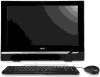
Computer Tour Top View Figure 1-1. Top View Table 1-1. Top View # Icon 1 Item Camera Hinge Description Adjust camera direction 8 - Acer Aspire Z1620 | Acer Aspire Z1620 Desktop Service Guide - Page 19
Front View Figure 1-2. Front View Table 1-2. Front View # Icon 1 2 Camera Item Power button Description Power on or off the system. 9 - Acer Aspire Z1620 | Acer Aspire Z1620 Desktop Service Guide - Page 20
-out Connects to audio line-in 5 port. devices(e.g.,speakers,headphones). 6 Card reader Card reader drive Connects to USB 3.0 devices 7 USB ports. (e.g.,USB mouse, USB camera). 10 - Acer Aspire Z1620 | Acer Aspire Z1620 Desktop Service Guide - Page 21
Right View Figure 1-4. Right View Table 1-4. Right View # Icon 1 Item Optical disk drive Description Accepts ODDs. 11 - Acer Aspire Z1620 | Acer Aspire Z1620 Desktop Service Guide - Page 22
Base View Figure 1-5. Base View Table 1-5. Base View # Icon 1 2 3 4 5 Item ODD door Power cord socket Description Remove ODD Connects power cable devices PS/2 mouse connector PS/2 keyboard connector USB ports. Connects to USB 2.0 devices (e.g.,USB mouse, USB camera). 12 - Acer Aspire Z1620 | Acer Aspire Z1620 Desktop Service Guide - Page 23
# Icon Item Description Lights to indicate the status of 6 Network port wireless LAN communications. 7 King Lock 8 Serial port 9 Printer Port Printer connector 10 TV Tuner Connects the TV cable devices 13 - Acer Aspire Z1620 | Acer Aspire Z1620 Desktop Service Guide - Page 24
screen moves one line up or down when the up or down arrow keys are pressed respectively. Scroll Lock does not work with some applications. The keyboard function Num Lock on Number keys on numeric Type numbers in a normal keypad manner. Num Lock off Navigate the screen by using Home, PgUp - Acer Aspire Z1620 | Acer Aspire Z1620 Desktop Service Guide - Page 25
: Undo minimize all windows + F1 : Show the help window + E : Open Windows Explorer + F : Search for a file or folder + D : Show the desktop Ctrl + + F : Search for computers (if you are on a network) + L : Lock your computer (if you are connected to a network domain), or switch users (if you - Acer Aspire Z1620 | Acer Aspire Z1620 Desktop Service Guide - Page 26
Quick Launch Keys The keyboard contains 11 quick launch keys which can be used to access most of the computer's controls like volume output Key Function Sleep Search Internet Email Play/Pause Description Puts the computer in Sleep mode. Activate the default internet/file search function Use - Acer Aspire Z1620 | Acer Aspire Z1620 Desktop Service Guide - Page 27
Table 1-9. Quick Launch Keys (Continued) Key Function VOL- Volume decrease VOL+ Volume increase Speaker toggle Description Decreases the volume. Increases the volume. Turns the speakers on and off. 17 - Acer Aspire Z1620 | Acer Aspire Z1620 Desktop Service Guide - Page 28
Sandy Bridge Desktop Processor Socket H2 DDR3 SODIMM Channel A DDR3 SODIMM Channel B DDR3 1333MHz/1066MHz Total Max 8GB DMI FDI MINI PCI-EX1 (FULL) MINI PCI-EX1 (HALF) SATA 2.0 3Gbps PORT1 ETRON USB3.0 PORT2 IC PCIE X1 Switch IC PCIE X16 FROM CPU Ext VGA NVRAM has been Remove From PDG - Acer Aspire Z1620 | Acer Aspire Z1620 Desktop Service Guide - Page 29
Specification Tables Computer specifications Item Metric Imperial Dimensions Width 522 mm 20.551 in Depth 60 mm 2.3622 in Height 370 mm 14.5632 in Weight: Non-Touch Screen 8.0 kg 17.64 lb Input power Operating voltage 19V (150 W) Operating current 7.89A Temperature - Acer Aspire Z1620 | Acer Aspire Z1620 Desktop Service Guide - Page 30
Port is also implemented in the Ibex Peak Super I/O controller ITE 8728 Bluetooth N/A Wireless Supports Mini PCIE wireless LAN TV Supports Mini PCIE TV PCMCIA N/A Audio codec Realtek ALC887VD Card reader RTS5138 One-LUN USB 2.0 Card Reader Controller SD, SDHC, MMC, MS, MS pros lot 20 - Acer Aspire Z1620 | Acer Aspire Z1620 Desktop Service Guide - Page 31
cores A 32-KB instruction and 32-KB data first-level cache (L1) for each core A 256-KB shared instruction/data second-level cache (L2) for each core 8 MB shared instruction/data Last-Level Cache = 71 °C CPU Tj >= 83 H/W shut down by EC SPL Spec (dBA) 26dBA 28dBA 32dBA 35dBA 38dBA 42dBA 21 - Acer Aspire Z1620 | Acer Aspire Z1620 Desktop Service Guide - Page 32
System Memory Item Memory controller Memory size DIMM socket number Supports memory size per socket Supports maximum memory size Supports DIMM type Supports DIMM Speed Support DIMM voltage Supports DIMM package Memory Combinations Slot 1 (MB) 0 1024 1024 0 2048 2048 4096 0 4096 Video Interface Item - Acer Aspire Z1620 | Acer Aspire Z1620 Desktop Service Guide - Page 33
BIOS Version BIOS ROM type BIOS ROM size Features LAN Interface Item LAN Chipset LAN connector type LAN connector location Features Keyboard Item Type Total number of keypads Windows logo key Internal & external keyboard work simultaneously Features Specification American Megatrends, Inc. 2.10 - Acer Aspire Z1620 | Acer Aspire Z1620 Desktop Service Guide - Page 34
Hard Disk Drive (AVL components) Item Specification Vendor & Model Name HDS723015 WD5000AAKX max) DC Power Requirements Voltage 5V ± 5% tolerance 12V +10% 320 2 1 16 5V +10% / -7.5% 12V +10% / -7.5% 500 2 1 16 5V +10% / -7.5% 12V +10% / -7.5% 500 2 1 16 5V ± 5% 12V ± 10% WD10EADX - - Acer Aspire Z1620 | Acer Aspire Z1620 Desktop Service Guide - Page 35
Memory Sustained Sustained Max 3.6Mbytes/sec Max 10.08Mbytes/sec 2 MB SATA CD: DVD-R (3.9GB, 4.7GB) DVD-R DL, DVD-RW, DVD-RAM, DVD+R, DVD+R DL, DVD+RW CD: CD-DA (Red Book Book) - MPEG1 Video CD-R (Orange Book Part) CD-RW & HSRW (Orange Book Part Volume1 & Volume 2 Super Audio CD (SACD - Acer Aspire Z1620 | Acer Aspire Z1620 Desktop Service Guide - Page 36
Item Vendor & Model name Performance Specification Transfer rate (KB/sec) Buffer Memory Interface Applicable disc format Loading mechanism Power Requirement Input Voltage LCD 20"/21.5" Item Vendor/Model CMI/M200O3 name -LA3 Screen 20 inches Diagonal (mm) Active Area (mm) 442.8 Specification - Acer Aspire Z1620 | Acer Aspire Z1620 Desktop Service Guide - Page 37
Tr: 1.5ms Tf: 3.5ms Time) msec Typical Power Consumption 13.48W (watt) Weight (without 1750g converter) Physical Size (mm) Electrical 30 pins Interface 2ch-LVDS Viewing Angle (degree) 170H 160V CR > 10 (Left) Specification 1920x1080 0.2482 (H) x 0.2482 (V) 1600x900 1920x1080 - Acer Aspire Z1620 | Acer Aspire Z1620 Desktop Service Guide - Page 38
) Output current Vendor & Model name Specification Espower & IV45080/T-LF Duty 20%~100% (3.3V) , F=200Hz 19v ± 10% 0.6A 43.4V 50 mA Espower & IV45080/T-LF Display Supported Resolution (LCD) Resolution 16 bits 32 bits Intel NVIDIA ATI 800x600p/60Hz 16:9 1024x768p/60Hz 16:9 1280x600/60Hz 16 - Acer Aspire Z1620 | Acer Aspire Z1620 Desktop Service Guide - Page 39
Specification Yes Memory Interface Avivo™ Display System Motion Video Acceleration Features Power Management Features Spread-Spectrum Support Internal Thermal Sensor Thermal Diode 3G Card (N/A) Item Features Specification Display Supported Resolution (GPU) Resolution 16 bits - Acer Aspire Z1620 | Acer Aspire Z1620 Desktop Service Guide - Page 40
CNF 9250 Foxlink FO20FF-232H-3 1.3M Mini Card Item Number supported Features 2 WLAN TV Card Specification Audio Interface Internal speaker/quantity Specification ALC272 supports Azalia function Onboard Mono HD audio Interface Sample rate up to 192Khz resolution VSR (Variable Sampling Rate - Acer Aspire Z1620 | Acer Aspire Z1620 Desktop Service Guide - Page 41
Supports EAPD (External Amplifier Power Down) control for external amplifier Supports anti-pop mode when analog power AVDD is on and digital power is off Supports load (5V power is supplied) No external output L-C filter required Speaker amplifier power supplies from 3.3V to 5V 10µA Shut - Acer Aspire Z1620 | Acer Aspire Z1620 Desktop Service Guide - Page 42
Battery Type Pack capacity Number of battery cell Package configuration VRAM (N/A) Item Chipset Memory size Interface USB Port Item USB compliance level EHCI Specification Specification Specification 2.0 The PCH contains seven USB full/low-speed host controllers that support the standard Universal - Acer Aspire Z1620 | Acer Aspire Z1620 Desktop Service Guide - Page 43
of HDMI port(s) Location Specification AC Adapter Item Input rating Maximum input AC current Inrush current Efficiency 135W 1.5A 3.15A Refer to EPA 2.0 Specification System Power Management Item Specification Mech. Off (G3) All devices in the system are turned off completely Soft Off (G2 - Acer Aspire Z1620 | Acer Aspire Z1620 Desktop Service Guide - Page 44
: 2T MS/MS-PRO: 32G 2 in 1 card reader, supporting: Secure Digital™ (SD) Card, MultiMediaCard™ (MMC) Storage cards with adapter: miniSD™ System LED Indicator Item Lock System state HDD access state Wireless state Power button backlight Battery state Specification N/A White color solid on - Acer Aspire Z1620 | Acer Aspire Z1620 Desktop Service Guide - Page 45
System Interrupt Specification Hardware IRQ System Function IRQ0 System timer IRQ1 Standard PS/2 Keyboard IRQ2 IRQ3 Not in use Intel® 6 Series/C200 Series Chipset Family SMBus Controller 1C22 IRQ5* Not in use IRQ6 Not in use IRQ7* Not in - Acer Aspire Z1620 | Acer Aspire Z1620 Desktop Service Guide - Page 46
Standard PS/2 Keyboard Motherboard resources Microsoft ACPI-Compliant Embedded Controller Motherboard resources System CMOS/real time clock Motherboard resources Motherboard resources Direct memory access controller Motherboard resources Direct memory access controller Motherboard resources Direct - Acer Aspire Z1620 | Acer Aspire Z1620 Desktop Service Guide - Page 47
System board 454 - 457 Motherboard resources 458 - 47F System board 4D0 - 4D1 Motherboard resources 500 - 57F Desktop/Workstation/Server Express Chipset SATA AHCI F090 - F097 Controller Intel® Desktop/Workstation/Server Express Chipset SATA AHCI F0A0 - F0A3 Controller Intel® Desktop - Acer Aspire Z1620 | Acer Aspire Z1620 Desktop Service Guide - Page 48
CHAPTER 2 System Utilities - Acer Aspire Z1620 | Acer Aspire Z1620 Desktop Service Guide - Page 49
BIOS Setup Utility 40 Navigating the BIOS Utility 40 BIOS...41 Main ...41 Advanced ...43 Power ...44 Security ...45 Boot Options ...50 Exit ...51 BIOS Flash Utilities 52 DOS Flash Utility...53 39 - Acer Aspire Z1620 | Acer Aspire Z1620 Desktop Service Guide - Page 50
and optimized so most users do not need to run it. If configuration problems occur, the setup utility may need to be run. Refer to Chapter 4, Troubleshooting when a problem arises. To activate the utility, press F2 during POST (power-on self-test) when prompted at the bottom of screen. The default - Acer Aspire Z1620 | Acer Aspire Z1620 Desktop Service Guide - Page 51
to switch between Date elements Memory Size Product Name System Serial Number Asset Tag Number System Date System Time 4096MB Aspire Z1620 [Thu 04/21/2011] [06:24:59] Move Enter:Select +/-/space:Change Opt. F7:Load User Defaults Setting F8:Save as User Default Setting F9:Load Optimized Defaults - Acer Aspire Z1620 | Acer Aspire Z1620 Desktop Service Guide - Page 52
Main Parameter Version Build Date EC Firmware Processor Core Frequency Count Memory Size Product Name System Serial Number Asset Tag Number System Date System Time Description BIOS version Creation date of BIOS System EC version CPU (central processing unit) type Speed of system Amount of cores - Acer Aspire Z1620 | Acer Aspire Z1620 Desktop Service Guide - Page 53
PC Health Status Move Enter:Select +/-/space:Change Opt. F7:Load User Defaults Setting F8:Save as User Default Setting F9:Load Optimized Defaults Setting F10:Save & Exit Setup ECS:Discard Change and Exit Setup Version 2.10.1207. © Copyright 2002-2011, Acer Inc. Figure 2-2. BIOS Advanced - Acer Aspire Z1620 | Acer Aspire Z1620 Desktop Service Guide - Page 54
Version 2.10.1207. © Copyright 2002-2011, Acer Inc. Figure 2-3. BIOS Power Table 2-3 describes the parameters shown in Figure 2-3. Table 2-3. BIOS Power Parameter Deep Power Off Mode Power On RTC Wakeup Support Power On by Onboard LAN Wake Up by USB KB/Mouse Restore On AC Power Loss Description - Acer Aspire Z1620 | Acer Aspire Z1620 Desktop Service Guide - Page 55
Security The Security tab shows parameters that safeguard and protect the computer from unauthorized use. BIOS Setup Utility Main Advanced Power Security Boot Options Exit Supervisor Password User Password Change Supervisor Password Not Installed Not Installed [Press Enter] Valid Keys: (1)a-z - Acer Aspire Z1620 | Acer Aspire Z1620 Desktop Service Guide - Page 56
password, three attempts are allowed before system halts. Resetting BIOS password may require computer be returned to dealer. Password on Boot must be set to Enabled to activate password feature. Passwords are not case sensitive. A password must be alphanumeric (A-Z, a-z, 0-9), not longer than 12 - Acer Aspire Z1620 | Acer Aspire Z1620 Desktop Service Guide - Page 57
new password strings match, the Setup Notice dialog screen is shown (Figure 2-6). If it is not Not Match a. Press Enter to return to the BIOS Setup Utility Security menu. b. The Supervisor Password password again, repeat steps 1 through 3. Removing a Password Perform the following: 1. Use the - Acer Aspire Z1620 | Acer Aspire Z1620 Desktop Service Guide - Page 58
ields. Computer will set Supervisor Password parameter to Clear. 4. Press F10 to save changes and exit the BIOS Setup Utility 10). If it is not shown, go to step 6. Setup Notice Changes have been saved. [Continue] Figure 2-10. Changing a Password: Setup Notice a. Press Enter to return to the BIOS - Acer Aspire Z1620 | Acer Aspire Z1620 Desktop Service Guide - Page 59
Changing a Password: Invalid Password a. Press Enter to return to the BIOS Setup Utility Security menu. b. The Supervisor Password parameter is shown as Password: Passwords Do Not Match a. Press Enter to return to the BIOS Setup Utility Security menu. b. The Supervisor Password parameter is shown as - Acer Aspire Z1620 | Acer Aspire Z1620 Desktop Service Guide - Page 60
All, but Keyboard] Move Enter:Select +/-/space:Change Opt. F7:Load User Defaults Setting F8:Save as User Default Setting F9:Load Optimized Defaults Setting F10:Save & Exit Setup ECS:Discard Change and Exit Setup Version 2.10.1207. © Copyright 2002-2011, Acer Inc. Figure 2-13. BIOS Boot Options - Acer Aspire Z1620 | Acer Aspire Z1620 Desktop Service Guide - Page 61
:Select +/-/space:Change Opt. F7:Load User Defaults Setting F8:Save as User Default Setting F9:Load Optimized Defaults Setting F10:Save & Exit Setup ECS:Discard Change and Exit Setup Version 2.10.1207. © Copyright 2002-2011, Acer Inc. Figure 2-14. BIOS Exit Table 2-4 describes the parameters shown - Acer Aspire Z1620 | Acer Aspire Z1620 Desktop Service Guide - Page 62
utility to update the system BIOS Flash ROM. NOTE: If a Crisis Recovery Disc is not available, create one before BIOS Flash utility is used. Refer to BIOS Recovery by Crisis Disk. NOTE: Do not install memory related drivers (XMS, EMS, DPMI) when BIOS Flash is used. NOTE: Use AC adaptor power supply - Acer Aspire Z1620 | Acer Aspire Z1620 Desktop Service Guide - Page 63
:Discard Change and Exit Setup Version 2.10.1207. © Copyright 2002-2011, Acer Inc. Figure 2-15. Change BIOS Boot priority Order 4. Copy the BIOS file to USB HDD. 5. Insert the USB HDD and reboot computer to DOS mode. 6. Execute A to update BIOS. NOTE: During update, do not press any keys. 7. When - Acer Aspire Z1620 | Acer Aspire Z1620 Desktop Service Guide - Page 64
CHAPTER 3 Machine Maintenance Procedures - Acer Aspire Z1620 | Acer Aspire Z1620 Desktop Service Guide - Page 65
Module Installation 77 HDD Module Removal ...78 HDD Module Installation 79 HDD Bracket Removal...80 HDD Bracket Installation 80 Power Supply Removal ...81 Power Supply Installation 82 Thermal Module Removal 83 Thermal Module Installation 84 Fan Module Removal ...85 Fan Module Installation 85 - Acer Aspire Z1620 | Acer Aspire Z1620 Desktop Service Guide - Page 66
Installation 97 Mainboard Removal ...98 Mainboard Installation ...99 Main frame Removal ...100 Main frame Installation 100 LCD Panel Removal ...101 LCD Panel Installation...102 Speaker Module Removal 103 Speaker Module Installation 103 Switch _LED& IR Module Removal 104 Power Switch_ LED & IR - Acer Aspire Z1620 | Acer Aspire Z1620 Desktop Service Guide - Page 67
, a list of tools needed to perform the required maintenance and step by step procedures on how to remove and install components from the computer. General Information The product previews seen in the following procedures may not represent the final product color or configuration. Cable paths - Acer Aspire Z1620 | Acer Aspire Z1620 Desktop Service Guide - Page 68
the required screws and fasteners required when performing any maintenance on the computer. Table 3-1. Main Screw List Screw M2.0x4.0 M2.2xL4.0mm M3.0xL5.0mm M3.0xL6.0mm 6#32xL5.0mm 6#32xL7.5mm M4.0xL6.0mm M4.0xL12.0mm 4-40xL6.0mm &NUT#4-40xL5.0mm Quantity 6 6 38 4 9 8 2 3 4 Acer Part Number 58 - Acer Aspire Z1620 | Acer Aspire Z1620 Desktop Service Guide - Page 69
and installation sequences. It provides information on what components need to be removed and installed during servicing. ODD HOLE COVER Stand ODD Module Rear IO Cover Rear Cover VESA Bracket Mainboard Cover Thermal Module FAN Power Supply Converter Module HDD Module Wlan Module Camera - Acer Aspire Z1620 | Acer Aspire Z1620 Desktop Service Guide - Page 70
order of the sequence to avoid damage to any of the hardware components. Perform the following prior to performing any maintenance procedures: 1. Remove power (A) from the system and peripherals. (Figure 3-2-1/2) 2. Remove all cables from system. 3. Place system on a stable work surface. A Figure - Acer Aspire Z1620 | Acer Aspire Z1620 Desktop Service Guide - Page 71
3-3) A B Figure 3-3. Rear Cover and Odd hole cover 2. Press ODD hole cover button. (Figure 3-4) Figure 3-4. ODD hole cover 3. Rotation ODD hole cover in an angle, and remove it. as shown in Figure 3-5. Figure 3-5. Remove ODD hole cover 61 - Acer Aspire Z1620 | Acer Aspire Z1620 Desktop Service Guide - Page 72
screw (C) from rear cover. (Figure 3-6) C Figure 3-6. Remove screw from rear cover 5. Push slim ODD bracket with tool that diameter less than 3.0mm. (Figure 3-7) D Figure 3-7. Push ODD bracket 6. Slide and remove ODD module through ODD slot (D) on rear cover. 7. Press ODD tray release button on - Acer Aspire Z1620 | Acer Aspire Z1620 Desktop Service Guide - Page 73
8. Slide ODD tray (E) from ODD module. (Figure 3-9) F G E Figure 3-9. Remove ODD bezel 9. Unlock latch (F) to separate ODD bezel (G) from tray. 10.Remove ODD bezel. 11.Remove screws (H) from ODD slim bracket (I) and ODD module. (Figure 3-10) H I Figure 3-10. Remove ODD slim bracket screw. 63 - Acer Aspire Z1620 | Acer Aspire Z1620 Desktop Service Guide - Page 74
ODD Module Installation 1. Install ODD slim bracket (H) to ODD module. (Figure 3-10) 2. Install and secure screws (I) from ODD slim bracket to ODD module. 3. Install ODD bezel (G) to ODD tray (E). (Figure 3-9) 4. Install and secure latch (F) to tray. 5. Install - Acer Aspire Z1620 | Acer Aspire Z1620 Desktop Service Guide - Page 75
. (Figure 3-12) B Figure 3-12. Remove stand screws. 3. Remove rear stand. Rear Stand Installation 1. Install rear stand (A) to rear cover. (Figure 3-12) 2. Install and secure screws (B) from stand to rear cover. 3. Push rear stand(A) until operating angle of 10 degrees. (Figure 3-11) ID Size - Acer Aspire Z1620 | Acer Aspire Z1620 Desktop Service Guide - Page 76
Rear IO Cover Removal 1. Lift rear IO cover (A) from slot (B) to unlock and separate from rear cover. (Figure 3-13) A B Figure 3-13. Unlock rear IO cover 2. Rotation rear IO cover in an angle, as shown in Figure 3-14. 3. Remove rear IO cover. Figure 3-14. Remove rear IO cover 66 - Acer Aspire Z1620 | Acer Aspire Z1620 Desktop Service Guide - Page 77
Rear IO Cover Installation 1. Locate flanges (C) on rear IO cover. (Figure 3-15) Figure 3-15. Rear IO cover 2. Install rear IO cover flanges into slots (D) on rear cover. (Figure 3-16) D Figure 3-15. Push rear IO cover 3. Install rear IO cover to rear cover. 4. Press along edges until rear IO cover - Acer Aspire Z1620 | Acer Aspire Z1620 Desktop Service Guide - Page 78
Rear Cover Removal Prerequisite: ODD Module Removal Rear Stand Removal Rear IO Cover Removal 1. Remove screws (A) from rear cover(B) and front cover(C). (Figure 3-17) B C A Figure 3-17. Remove rear cover screws. 2. Push rear cover from front cover that the distance is 5.0mm(B). (Figure 3-18) B - Acer Aspire Z1620 | Acer Aspire Z1620 Desktop Service Guide - Page 79
3. Lift rear cover from front cover. (Figure 3-19) Figure 3-19. Open rear cover 4. Remove rear cover. 69 - Acer Aspire Z1620 | Acer Aspire Z1620 Desktop Service Guide - Page 80
Rear Cover Installation 1. Install rear cover to front cover. (Figure 3-18) 2. Pull rear cover to front cover until coincide. (Figure 3-20) Figure 3-20. Pull rear cover 3. Install and secure screws (A) to front cover. (Figure 3-17) 4. Install rear IO cover. 5. Install rear stand. 6. Install ODD - Acer Aspire Z1620 | Acer Aspire Z1620 Desktop Service Guide - Page 81
VESA Bracket Removal Prerequisite: Rear Cover Removal 1. Remove screws (C) from VESA Bracket (A) and Main frame (B).(Figure 3-21) A B C Figure 3-21. Remove VESA Bracket screws. 2. Slide and remove VESA Bracket. (Figure 3-22) Figure 3-22. Slide VESA Bracket. 71 - Acer Aspire Z1620 | Acer Aspire Z1620 Desktop Service Guide - Page 82
VESA Bracket Installation 1. Install VESA bracket to main frame. (Figure 3-21) 2. Install and secure screws (C) from VESA bracket to main frame. 3. Install rear cover. ID Size Quantity Screw Type A M4.0x6.0 2 72 - Acer Aspire Z1620 | Acer Aspire Z1620 Desktop Service Guide - Page 83
Bracket Removal Prerequisite: VESA Bracket Removal 1. Remove screws (C) from EMI top Bracket (A) and EMI side (B).(Figure 3-23) A B C Figure 3-23. Remove EMI top Bracket screws. 2. Rotation EMI Top Bracket in an angle, as shown in Figure 3-24. Figure 3-24. Rotation EMI top Bracket. 3. Removal EMI - Acer Aspire Z1620 | Acer Aspire Z1620 Desktop Service Guide - Page 84
EMI Top Bracket Installation 1. Locate flanges (D) on EMI Top Bracket. (Figure 3-25) D Figure 3-25. EMI top Bracket. 2. Install EMI Top Bracket flanges into slots (E) on EMI side. (Figure 3-26) E Figure 3-26. Install EMI Top Bracket 3. Install and secure screws (C) from EMI top Bracket to EMI side - Acer Aspire Z1620 | Acer Aspire Z1620 Desktop Service Guide - Page 85
the following cable. Converter to mainboard cable (D) from converter board connector (C). Remove Converter cable (D) from guide (E). Converter to mainboard cable (D) from mainboard connector (F). 3. Remove screws (G) from EMI converter shield (H) and ODD bracket (B).(Figure 3-25) 4. Slide - Acer Aspire Z1620 | Acer Aspire Z1620 Desktop Service Guide - Page 86
5. Disconnect Converter to LCD panel cable (K) from converter board (J ) connector (I) (Figure 3-26-1/2) I K Figure 3-26-1. For LG Panel I K Figure 3-26-2. For CHIMEI Panel 6. Remove converter board from ODD bracket. J J 76 - Acer Aspire Z1620 | Acer Aspire Z1620 Desktop Service Guide - Page 87
: Converter to mainboard cable (D) to Cnverter board connector (C) (Figure 3-24) Converter to mainboard cable (D) to mainboard connector (F) (Figure 3-24) Secure Converter to mainboard cable (D) to guide (E). 6. Install EMI top. ID Size Quantity Screw Type A M3.0x5.0 3 77 - Acer Aspire Z1620 | Acer Aspire Z1620 Desktop Service Guide - Page 88
(B). ODD cable (F) from mainboard connector (C). Power cable (G), HDD cable (E) and ODD cable (F) from guide (H). HDD cable (E) from guide (I). 3. Remove screws (J) from ODD connector (K) on main frame. 4. Remove ODD connector (K). 5. Remove screws (N) from HDD module(A) on main frame - Acer Aspire Z1620 | Acer Aspire Z1620 Desktop Service Guide - Page 89
HDD cable (E) to mainboard connector (B). ODD cable (F) to mainboard connector (C). Secure power cable (G), HDD cable (E) and ODD cable (F) to guide (H) on main frame. Secure HDD cable (E) to guide (I) on AC-IN bracket. 5. Install EMI top. ID Size Quantity Screw Type N M3.0x5.0 2 79 - Acer Aspire Z1620 | Acer Aspire Z1620 Desktop Service Guide - Page 90
from HDD module connector (D). (Figure 3-29) Front Back B C A D E B Figure 3-29. Remove HDD. 2. Remove screws (B) from HDD bracket (E). 3. Peel electricity conductive tape (A) from HDD module and HDD Bracket. 4. Remove HDD carrier (E) from HDD module. HDD Bracket Installation 1. Install HDD - Acer Aspire Z1620 | Acer Aspire Z1620 Desktop Service Guide - Page 91
F IA C D B E Figure 3-30. Remove AC-IN and Power Supply. 2. Remove screws (G) from AC-IN bracket (I)on main frame. 3. Remove AC-IN (A) from AC-IN bracket(I). 4. Remove AC-IN cable (C) from guide (D). 5. Remove screws (H) from power supply on main frame. 6. Disconnect Power supply cable (E) from - Acer Aspire Z1620 | Acer Aspire Z1620 Desktop Service Guide - Page 92
supply (B) to main frame. 3. Install and secure screws (H) to Power supply (B) on main frame. 4. Secure AC-IN cable (C) to guide (D). 5. Install AC-IN (A) to AC-IN bracket(I). 6. Install and secure screws (G) to AC-IN bracket(I). 7. Install HDD module. ID Size Quantity Screw Type G M3.0x5 - Acer Aspire Z1620 | Acer Aspire Z1620 Desktop Service Guide - Page 93
Thermal Module Removal Prerequisite: EMI TOP bracket Removal 1. Locate thermal module (A) on mainboard. (Figure 3-31) C B3 B4 B2 Figure 3-31. Remove thermal module B1 A 2. Loosen captive screws (B/1 - B/4) from mainboard. 3. Remove screws (C) from thermal module on main frame. 4. Remove thermal - Acer Aspire Z1620 | Acer Aspire Z1620 Desktop Service Guide - Page 94
module. The following thermal grease types are approved for use: 1. Remove all traces of thermal grease from CPU using a lint-free cloth (Figure 3-31) 4. Secure captive screws (B/1 - B/4) in numerical order from one (1) to four (4) to mainboard. 5. Install and secure screws (C) to thermal - Acer Aspire Z1620 | Acer Aspire Z1620 Desktop Service Guide - Page 95
Top Removal HDD Module Removal 1. Locate fan module (A) one main frame. (Figure 3-33) A F E D B C Figure 3-33. Remove fan module 2. Disconnect fan cable (B) from mainboard connector (C). 3. Remove cable (B) from guide (D) on EMI SIDE (E). 4. Remove screws (F) from fan module. 5. Remove fan - Acer Aspire Z1620 | Acer Aspire Z1620 Desktop Service Guide - Page 96
3-35) 6. Peel acetate cloth (H) from EMI side. 7. Remove antenna cable (D) from guide (I) on main frame. 8. Remove antenna cables (C,D) from guide (J) on front cover. 9. Peel Acetate Cloth (H) from main frame. 10. Peel AL-foil (G) from main frame. 11. Remove antenna brackets (K, L) from front cover - Acer Aspire Z1620 | Acer Aspire Z1620 Desktop Service Guide - Page 97
cover. 6. Secure antenna cables (D) to guide (I) on front cover. 7. Install acetate cloth (H) from main frame. 8. Secure antenna cables (C, D) to guide (F) on EMI side. 9. Connect WLAN main (C) and auxiliary (D) antenna cables to WLAN module. (Figure 3-34) 10. Install EMI top. ID Size Quantity - Acer Aspire Z1620 | Acer Aspire Z1620 Desktop Service Guide - Page 98
Camera Module Removal Prerequisite: EMI Top bracket Removal 1. Remove screws (A) from front cover. (Figure 3-36) 2. Peel Acetate Cloth (C) from EMI side. 3. Remove camera cable (D) from guide (E) on EMI side. 4. Disconnect camera cable (D) from mainboard connector (F) 5. Remove camera module (G) - Acer Aspire Z1620 | Acer Aspire Z1620 Desktop Service Guide - Page 99
7. Remove screws (A) from camera hinge. (Figure 3-38) 8. Remove camera module (J) from camera hinge. A J Figure 3-38. Remove camera module. 9. Disconnect camera cable (D) from module connector (K). (Figure 3-39) K D Figure 3-39. Disconnect camera cable. 89 - Acer Aspire Z1620 | Acer Aspire Z1620 Desktop Service Guide - Page 100
and secure screws (A) to camera module and front cover. 7. Connect camera cable (D) to mainboard connector (F) 8. Secure camera cable (D) to guide (E) on EMI side. 9. Secure camera cable (D) to guide (C) on EMI side. 10. Install WLAN module. ID Size Quantity Screw Type z A M2.0x4.0 4 90 - Acer Aspire Z1620 | Acer Aspire Z1620 Desktop Service Guide - Page 101
3-40) 2. Disconnect VGA cable (B) from VGA module connector (F). 3. Remove cable (B) from guide (C) on EMI SIDE. 4. Remove screws (E) from main frame. 5. Remove VGA module (A) from mainboard. A B E F C D Figure 3-40. Remove VGA module from mainboard VGA Module Installation 1. Install VGA - Acer Aspire Z1620 | Acer Aspire Z1620 Desktop Service Guide - Page 102
Rear IO Module Removal Prerequisite: Converter Module Removal Fan Module Removal HDD Module Removal 1. Disconnect LPT&COM cable (B) from mainboard connector (D). (Figure 3-41) 2. Remove TV tuner cable (C) and LPT&COM cable (B) from guide (D) on EMI side. 3. Remove screws (E) from main frame. 4. - Acer Aspire Z1620 | Acer Aspire Z1620 Desktop Service Guide - Page 103
slots (L) on main frame. (Figure 3-43) 6. Install and secure screws (E) to main frame. 7. Secure TV tuner cable (C) and LPT&COM cable (B) to guide (D) on EMI side. 8. Connect LPT&COM cable (B) to mainboard connector (D). 9. Install EMI top. L Figure 3-43. Install Rear IO module into slots on main - Acer Aspire Z1620 | Acer Aspire Z1620 Desktop Service Guide - Page 104
CPU Removal Prerequisite: Thermal Module Removal 1. Locate CPU module (A) on mainboard. (Figure 3-44) 2. Release lever (B) from latch (C). A B C Figure 3-44. Locate CPU module on mainboard. 3. Move lever until CPU holder (D) clears guide (E) and lifts open. (Figure 3-45) 4. Remove CPU from socket. G - Acer Aspire Z1620 | Acer Aspire Z1620 Desktop Service Guide - Page 105
CPU Installation 1. Align CPU marker (F) with socket marker (G) and install CPU to socket. (Figure 3-45) 2. Install CPU holder (D) until covering CPU. 3. Move lever (B) until CPU holder is inserted to guide (E). 4. Install and secure lever to latch (C). (Figure 3-44) 5. Install thermal module. 95 - Acer Aspire Z1620 | Acer Aspire Z1620 Desktop Service Guide - Page 106
clips (A) to unlock DIMM. (Figure 3-46) 2. Disconnect DIMM (B) from mainboard connector (D). 3. Disconnect DIMM (C) from mainboard connector (E). 4. Remove DIMM. B C D A A E Figure 3-46. DIMM DIMM Installation 1. Connect DIMM (B) into mainboard connector (D). (Figure 3-46) 2. Connect DIMM - Acer Aspire Z1620 | Acer Aspire Z1620 Desktop Service Guide - Page 107
1. Disconnect KTS Battery cables (C) from mainboard connector (B). (Figure 3-47) 2. Remove KTS Battery (A) from mainboard. A B C Figure 3-47. Remove KTS Battery + IMPORTANT: Follow local regulations for battery disposal. KTS Battery Installation 1. Install KTS Battery (A) to mainboard. (Figure - Acer Aspire Z1620 | Acer Aspire Z1620 Desktop Service Guide - Page 108
Mainboard Removal Prerequisite: DIMM Removal WLAN Module Removal KTS Battery Removal CPU Removal 1. Disconnect the following cables: (Figure 3-48) Speaker cable (A) from mainboard connector (a). IR cable (B) from mainboard connector (b). Power switch cable (C) from mainboard connector (c) - Acer Aspire Z1620 | Acer Aspire Z1620 Desktop Service Guide - Page 109
and secure screws (E) to mainboard. 3. Connect the following cables: Speaker cable (A) to mainboard connector (a). IR cable (B) to mainboard connector (b). Power switch cable (C) to mainboard connector (c) LVDS cable (D) to mainboard connector (d1) LVDS cable (D) to mainboard connector (d2 - Acer Aspire Z1620 | Acer Aspire Z1620 Desktop Service Guide - Page 110
nineteen (19) screws (A) from main frame (B). (Figure 3-50) 2. Remove main frame (B) from guide (D) on front cover (C). 3. Remove main frame(B) from front cover (C). D D B A D A A D A C Figure 3-50. main frame. Main frame Installation 1. Install main frame (B) to front cover (C). (Figure - Acer Aspire Z1620 | Acer Aspire Z1620 Desktop Service Guide - Page 111
LCD Panel Removal Prerequisite: Mainframe Removal 1. Peel acetate cloth (B) from panel. (Figure 3-51-1/2) 2. Disconnect converter cable (E) from LCD panel connector (G). 3. Remove LCD panel (I) from front cover (H). A B D C E Figure 3-51-1. For CHIMEI panel A B D C E Figure 3-51-2. For LG - Acer Aspire Z1620 | Acer Aspire Z1620 Desktop Service Guide - Page 112
Align and install LCD panel (D) to front cover. (Figure 3-51-1/2) 2. Connect converter cable (A) to LCD panel connector (C). 3. Secure converter cable (A) to guide (B) on LCD panel (D). 4. Install main frame. NOTE: The text of FFC cable should be shown outwards for LG panel.(Figure 3-52) Figure 3-52 - Acer Aspire Z1620 | Acer Aspire Z1620 Desktop Service Guide - Page 113
1. Locate left (A) and right (B) speakers on front cover. (Figure 3-52) 2. Remove screws (C) from speakers. 3. Remove speaker cable (D) from guides. 4. Remove Speaker Module from front cover. A B C D C Figure 3-52. For CHIMEI panel Speaker Module Installation 1. Align and install left (A) and - Acer Aspire Z1620 | Acer Aspire Z1620 Desktop Service Guide - Page 114
& LED Module (A) on front cover. (Figure 3-53) 2. Remove screws (B) from speakers. 3. Remove Power Switch _LED(C)& IR (D) cables from guides. 4. Remove Power Switch _LED& IR Module from guide (E, F) on front cover . 5. Remove Power Switch & IR& LED module from front cover. F B C A E D Figure - Acer Aspire Z1620 | Acer Aspire Z1620 Desktop Service Guide - Page 115
CHAPTER 4 Troubleshooting - Acer Aspire Z1620 | Acer Aspire Z1620 Desktop Service Guide - Page 116
Introduction 107 General Information 107 Common Problems...108 LCD Failure ...109 Wireless Function Failure 112 Component Failure ...113 Other Functions Failure 115 Intermittent Problems 121 Undetermined Problems 121 Post Codes ...122 106 - Acer Aspire Z1620 | Acer Aspire Z1620 Desktop Service Guide - Page 117
. General Information The following procedures are a guide for troubleshooting computer problems. The step by step procedures are designed to be performed as described. NOTE: The diagnostic tests are intended for Acer products only. Non-Acer products, prototype cards, or modified options can give - Acer Aspire Z1620 | Acer Aspire Z1620 Desktop Service Guide - Page 118
Use the following procedure as a guide for computer problems. 1. Obtain the failing symptoms in as much detail as possible. 2. Verify the symptoms by attempting to re-create the failure by running the diagnostic test or by repeating the same operation. 3. Use the troubleshooting sections to try and - Acer Aspire Z1620 | Acer Aspire Z1620 Desktop Service Guide - Page 119
LCD Failure If the LCD Display fails, perform the following: LCD Failure Is the LVDS cable properly connected? F Re-Insert the cable OK Fail Close Test the LVDS Cable F Replace the cable OK Close Fail Is the Inverter properly connected? F Re-Insert the cable OK Fail Close Test the - Acer Aspire Z1620 | Acer Aspire Z1620 Desktop Service Guide - Page 120
7. Disconnect power and all external devices including port replicators or docking stations. Remove any memory cards and CD/DVD discs. 8. Start the computer. If the computer boots correctly, add the devices one by one until the failure point is discovered. 9. Reseat the memory modules. 10.Remove the - Acer Aspire Z1620 | Acer Aspire Z1620 Desktop Service Guide - Page 121
, right-click on the desktop and select Personalize Display Settings. Click and drag the Resolution slider to the desired resolution. Click Apply and check the display. Readjust if necessary. 4. Roll back the video driver to the previous version if updated. 5. Remove and reinstall the video - Acer Aspire Z1620 | Acer Aspire Z1620 Desktop Service Guide - Page 122
Wireless Function Failure If the WLAN fails, perform the following: START Wireless function failure Check WLAN cable connection NG Reconnect cable correctly OK OK NG Close Check WLAN module OK NG Replace WLAN module OK NG Close Replace Mainboard OK Close Figure 4-3. Wireless - Acer Aspire Z1620 | Acer Aspire Z1620 Desktop Service Guide - Page 123
the flowchart to perform the following: Component Failure Touch Screen Failure Wireless LAN Failure Speaker Failure Camera Failure ODD Failure Component pass Test component on test bed Change cables Yes Cable connected properly? Component fail Yes NO Replace Mainboard Replace module - Acer Aspire Z1620 | Acer Aspire Z1620 Desktop Service Guide - Page 124
Speaker Setup. Follow the on-screen prompts to configure the speakers. 8. Remove any recently installed hardware or 10. If the issue is remains, repeat step 9, selecting an earlier time and date. 11. Reinstall the Operating System. 12. If the Issue is still not resolved, refer to Online Support - Acer Aspire Z1620 | Acer Aspire Z1620 Desktop Service Guide - Page 125
Repair. NOTE: Startup Repair attempts to locate and resolve issues with the computer. h. When complete, click Finish.If an issue is discovered, follow the on-screen information to resolve the problem. 1. Run the Windows Memory Diagnostic Tool. For more information see Windows Help and Support. 115 - Acer Aspire Z1620 | Acer Aspire Z1620 Desktop Service Guide - Page 126
or not active: Not shown in My Computer or the BIOS setup LED does not flash when the computer starts up The tray does not eject Access failure screen is shown The ODD is noisy Perform the following, one at a time: 1. Boot the computer and retry the operation. 2. Use an different disc - Acer Aspire Z1620 | Acer Aspire Z1620 Desktop Service Guide - Page 127
the selected media: +IMPORTANT: Region can only be changed a limited number of times. After Changes remaining reaches zero, the region cannot be changed even when Windows is reinstalled or the drive is moved to another computer. Navigate to StartControl PanelSystem and MaintenanceSystemDevice - Acer Aspire Z1620 | Acer Aspire Z1620 Desktop Service Guide - Page 128
the computer and press F2 to enter the BIOS Utility. 2. Verify that the drive is detected in the ATAPI Model Name field on the Information page. NOTE: Verify that the entry is identical to one of the ODDs specified in Hardware Specifications and Configurations. Remove power and remove the cover - Acer Aspire Z1620 | Acer Aspire Z1620 Desktop Service Guide - Page 129
discs, the original disc is probably defective and should be replaced. 3. Remove the power and remove the cover to inspect the connections to the ODD. Refer to Online Support Information. Check for broken connectors on the drive, motherboard, and cables. Check for bent or broken pins on the - Acer Aspire Z1620 | Acer Aspire Z1620 Desktop Service Guide - Page 130
10. Run the Event Viewer to check the events log for errors. For more information refer to Windows Help and Support. 11. Roll back the mouse driver to the previous version if updated recently. 12. Remove and reinstall the mouse driver. 13. Check the Device Manager to determine that: The device is - Acer Aspire Z1620 | Acer Aspire Z1620 Desktop Service Guide - Page 131
: Non-Acer devices Printer, mouse, and other external devices Battery pack Hard disk drive DIMM CD-ROM/Diskette drive Module PC Cards 4. Apply power to the computer. 5. Determine if the problem has changed. 6. If the problem does not recur, connect the removed devices one at a time - Acer Aspire Z1620 | Acer Aspire Z1620 Desktop Service Guide - Page 132
7. If the problem remains, replace the following FRUs one at a time. Do not replace a non-defective FRU: System board LCD assembly Post Codes The following are the InsydeH2O™ Functionality POST code tables. The components of the POST code table includes: SEC phase, PEI phase, DXE phase, BDS - Acer Aspire Z1620 | Acer Aspire Z1620 Desktop Service Guide - Page 133
CHAPTER 5 Jumper and Connector Locaions - Acer Aspire Z1620 | Acer Aspire Z1620 Desktop Service Guide - Page 134
Mainboard ...125 Clearing Password and BIOS Recovery 127 Clearing Password...127 BIOS Recovery by Crisis Disk 128 124 - Acer Aspire Z1620 | Acer Aspire Z1620 Desktop Service Guide - Page 135
Jumper and Connector Locations Mainboard 28 27 1 2 3 4 5 6 7 8 9 10 11 12 13 14 15 16 17 18 19 Figure 5-1. Mainboard Top 26 25 24 23 22 21 20 125 - Acer Aspire Z1620 | Acer Aspire Z1620 Desktop Service Guide - Page 136
Top Item Description 1 Camera Connector 3 LVDS 5 COM/Parallel Connector 7 CPU Fan Connector 9 SATA Power Connector 11 Logo Connector 13 Converter Connector 15 AC-DC Connector 17 P/S 2 Keyboard Connector 19 LAN Connector 21 Speaker Connector 23 Line-Out Connector 25 USB - Acer Aspire Z1620 | Acer Aspire Z1620 Desktop Service Guide - Page 137
Password and User Password). Clearing BIOS Password If a BIOS password (Supervisor Password and/or User Password) is set, the BIOS will prompt for the password at system POST or upon entering the BIOS setup menu. Clear the password check with the following procedure: 1. Remove AC adapter. 2. Locate - Acer Aspire Z1620 | Acer Aspire Z1620 Desktop Service Guide - Page 138
system with minimum BIOS initialization. Users can enable this feature to restore the BIOS firmware if a previous BIOS flashing process has failed. BIOS Recovery Hotkey To enable the BIOS Recovery process, use the function hotkey, Fn + Esc, during BIOS POST. The AC adapter and battery are required - Acer Aspire Z1620 | Acer Aspire Z1620 Desktop Service Guide - Page 139
.rom file to USB HDD. 5. Press Power button. 6. After several minutes, BIOS Setup Utility screen will appear as shown in Figure 5-4. Figure 5-4. BIOS Recovery Screen 7. Select Proceed with flash update. 8. Press Enter button to initiate BIOS Recovery mode. Flash will begin. (Figure 5-5) Figure - Acer Aspire Z1620 | Acer Aspire Z1620 Desktop Service Guide - Page 140
9. When BIOS Recovery is complete, press F10 to save and exit. 10. Press Del to return to BIOS setup menu. Update the latest BIOS version for this machine by the regular BIOS flashing process. 130 - Acer Aspire Z1620 | Acer Aspire Z1620 Desktop Service Guide - Page 141
CHAPTER 6 FRU (Field Replaceable Unit) List - Acer Aspire Z1620 | Acer Aspire Z1620 Desktop Service Guide - Page 142
Exploded Diagram 134 Main Assembly ...134 FRU List ...136 Screw List ...137 132 - Acer Aspire Z1620 | Acer Aspire Z1620 Desktop Service Guide - Page 143
on the regional web or channel. Part number changes will not be noted on the printed Service Guide. For Acer Authorized Service Providers, the Acer office may have a different part number code from those given in the FRU list of this printed Service Guide. Users MUST use the local FRU list provided - Acer Aspire Z1620 | Acer Aspire Z1620 Desktop Service Guide - Page 144
Exploded Diagram Main Assembly Figure 6-1. Main Assembly Exploded Diagram 134 - Acer Aspire Z1620 | Acer Aspire Z1620 Desktop Service Guide - Page 145
Diagram (Continued) No Description P/N 1 Front Cover Assy 2 Camera Hinge Assy 3 Camera Holder 4 Power switch &IR LED Holder 5 Panel Frame Assy 6 Tcm Bracket 7 ODD Bracket 8 Converter Bracket 9 EMI Top Bracket Assy 10 HDD Bracket Assy 11 Rear IO Bracket 12 VESA Bracket 13 Side IO - Acer Aspire Z1620 | Acer Aspire Z1620 Desktop Service Guide - Page 146
FRU List 136 - Acer Aspire Z1620 | Acer Aspire Z1620 Desktop Service Guide - Page 147
Screw List 137 - Acer Aspire Z1620 | Acer Aspire Z1620 Desktop Service Guide - Page 148
CHAPTER 7 Test Compatible Components - Acer Aspire Z1620 | Acer Aspire Z1620 Desktop Service Guide - Page 149
Microsoft® Windows® 7 Environment Test 140 139 - Acer Aspire Z1620 | Acer Aspire Z1620 Desktop Service Guide - Page 150
Microsoft® Windows® 7 Environment Test 140 - Acer Aspire Z1620 | Acer Aspire Z1620 Desktop Service Guide - Page 151
CHAPTER 8 Online Support Information - Acer Aspire Z1620 | Acer Aspire Z1620 Desktop Service Guide - Page 152
Introduction 143 142 - Acer Aspire Z1620 | Acer Aspire Z1620 Desktop Service Guide - Page 153
offers convenient and valuable support resources. In the Technical Information section users can download information on all of Acer's Notebook, Desktop and Server models including: Service guides for all models Bios updates Software utilities Spare parts lists TABs (Technical Announcement