Acer E191W Service Guide
Acer E191W - eMachines bm - 19" LCD Monitor Manual
 |
UPC - 884483187652
View all Acer E191W manuals
Add to My Manuals
Save this manual to your list of manuals |
Acer E191W manual content summary:
- Acer E191W | Service Guide - Page 1
E-machine E191W E191HQ E181H E161HQ Service Guide 1 - Acer E191W | Service Guide - Page 2
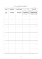
Version A00 Service Guide Version and Revision Release Date Jul.-25-2008 Revision History Initial Release Customer Model E191W E191HQ &E181H E161HQ TPV model T9RMNFH8X7GYAN T9RMNFH8X7GKAN T6RMNFH8X7GYAN 2 - Acer E191W | Service Guide - Page 3
manual or otherwise, without the prior written permission of Emachine Incorporated. Disclaimer The information in this guide is subject to change without notice. Emachine Incorporated makes no representations or warranties or software problems. Remind you to do specific actions relevant to - Acer E191W | Service Guide - Page 4
Preface Before using this information and the product it supports, please read the following general information. 1. This Service Guide provides you with all technical information relating to the BASIC CONFIGURATION decided for Emachine's "global" product offering. To better fit local market - Acer E191W | Service Guide - Page 5
with the monitor. If you mount the monitor on a wall or shelf, uses a mounting kit approved by the manufacturer and follow the kit instructions. z Slots accessible. Special Notes On LCD Monitors The following symptoms are normal with LCD monitor and do not indicate a problem. Notes z Due to the - Acer E191W | Service Guide - Page 6
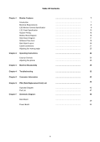
LCD Panel Specification Support Timing Monitor Block Diagram Main Board Diagram Software Flow chart Main Board Layout Cable Connections Adjusting the viewing angle Chapter 2 Operating Instructions External Controls Adjusting the picture Chapter 3 Machine Disassembly Chapter 4 Troubleshooting Chapter - Acer E191W | Service Guide - Page 7
supported high resolution color LCD monitor. This monitor can be directly connected to general 15-pin D-sub VGA connector and 24-pin DVI connector, also supports traditional CRT monitor, it consumes less power and gets less weight in addition MTBF target is 50k hours or more. Chart of E191W &(E181H - Acer E191W | Service Guide - Page 8
cm for LCD performance, 20 cm for LCD failures : >30 minutes : 5 seconds : Chroma 7120 signal generator or equivalent, directly Connected to the monitor under test. Minolta CA100 photometer, or equivalent : Set to Factory preset value (cut off raster) : Set to factory preset value, which - Acer E191W | Service Guide - Page 9
LCD Monitor General Specification 9 - Acer E191W | Service Guide - Page 10
LCD Panel Specification 1.M19PW01(E191W) This specification applies to the 19 inch-wide clor TFT-LCD Module M19PW01. The display supports the WXGA+(1440(H)X 900(V)screen format and 16.7 colors。All input signals are 2 Channel LVDS interface comlatible。 This module does not contain an inverter card - Acer E191W | Service Guide - Page 11
Specifications 2.M185B1-L01(E191HQ/E181H) M185B1-L01 is a 18.5" TFT Liquid Crystal Display module with 4 CCFL Backlight unit and 30pin1ch-LVDS interface. This module supports 1366 x 768 WXGA mode and can display up to 16.7M colors.The inverter module for Backlight is not built in。 LCD Panel Model 11 - Acer E191W | Service Guide - Page 12
Specifications 3. M156B1-L01 (E161HQ) M156B1-L01 is a 15.6" TFT Liquid Crystal Display module with 2 CCFL Backlight unit and 30pin 1ch-LVDS interface. This module supports 1366 x 768 WXGA mode and can display up to 16.7M colors. The inverter module for Backlight is not built in. LCD Panel Model 12 - Acer E191W | Service Guide - Page 13
Optical Specifications 13 - Acer E191W | Service Guide - Page 14
Supported Timing 14 - Acer E191W | Service Guide - Page 15
15 - Acer E191W | Service Guide - Page 16
Block Diagram The LCD MONITOR will contain a main board, a power board and a key board which house the flat panel control logic, brightness control logic and DDC. The Inverter board will - Acer E191W | Service Guide - Page 17
E161HQ Main Board Diagram U402 PM25LV010A LCD Interface CN403(E191W) CN405(E161HQ&E181H/E191HQ) U401 Scalar : NT68167FG QFP64 (Include: MCU, ADC, OSD etc) Crystal 14.318MHZ X401 OSD Control Interface (Key board) CN401 D-SUB Connector (CN101) 17 - Acer E191W | Service Guide - Page 18
Software Flow Chart 1 Y 2 3 N 4 N 5 Y 6 N 7 8 Y 9 N 10 11 Y N 12 N 13 Y Y N 14 15 16 Y 17 N 18 19 Y 18 - Acer E191W | Service Guide - Page 19
Remark: 1) MCU initializes. 2) Is the EEPROM blank? 3) Program the EEPROM by default values. 4) Get the PWM value of brightness from EEPROM. 5) Is the power key pressed? 6) Clear all global flags. 7) Are the AUTO and SELECT keys pressed? 8) Enter factory mode. 9) Save the power key status into - Acer E191W | Service Guide - Page 20
-3L DIODES IC AZC099-04S SOT23-6L IC PM25LV010A-100SCE SOIC-8 Symbol CN404 CN101 CN401 CN403 CN405 Description WAFER 2*6P 2.0MM R/A D-SUB 15PIN WAFER WAFER(E191W) WAFER(E161HQ&E181H/E191HQ) 20 - Acer E191W | Service Guide - Page 21
Cable Connections 21 - Acer E191W | Service Guide - Page 22
22 - Acer E191W | Service Guide - Page 23
it is recommended to look at the full face of the monitor, then adjust the monitor's angle to your own preference. 2、 Hold the stand so you do not topple the monitor when you change the monitor's angle. 3、 You are able to adjust the monitor's angle from -5° to 15°. NOTES 1、 Do not touch the LCD - Acer E191W | Service Guide - Page 24
Operating Instructions Chapter 2 Press the power button to turn the monitor on or off. The other control buttons are located at front panel of the monitor. By changing these settings, the picture can be adjusted to your personal preferences. • The power cord should be connected. • Connect the - Acer E191W | Service Guide - Page 25
Adjusting the Picture 25 - Acer E191W | Service Guide - Page 26
26 - Acer E191W | Service Guide - Page 27
User Press Hot-Key "Auto", will show this message, and the Please Wait monitor do the auto config function. Input Not Supported When the Hsync Frequency, Vsync Frequency or Resolution is out of the monitor support range, will show this message. This message will be flying. Cable Not Analog-Only - Acer E191W | Service Guide - Page 28
will appear to be non-functional if there is no video input signal. In order for this monitor to operate properly, there must be a video input signal. This monitor meets the Green monitor standards as set by the Video Electronics Standards Association (VESA) and/or the United States Environmental - Acer E191W | Service Guide - Page 29
Machine Disassembly Chapter 3 This chapter contains step-by-step procedures on how to assemble the monitor for maintenance. Disassembly Procedure 1. Remove hinge cover, then remove two screws marked A-C to remove base. (Fig 1) A C B 2. Remove the back cover. (Fig 2-3) Fig 1 Fig 2 29 - Acer E191W | Service Guide - Page 30
Fig 3 1. Remove the front bezel,disconnect the connector remarked in green (Fig 4,5) Key board Fig 4 Fig 5 2. 30 - Acer E191W | Service Guide - Page 31
3. Remove the screws marked in red and disconnect lamp connections to remove shield. (Fig 6-9) A Fig 6 C Fig 7 E Fig 8 B D F Fig 9 31 - Acer E191W | Service Guide - Page 32
4. Remove the screws marked in red and the wire connect with power board to remove the boards. (Fig 10,11) Fig 10 6. The monitor disassembly completely. (Fig 12) Fig 11 Fig 12 32 - Acer E191W | Service Guide - Page 33
This chapter provides troubleshooting information for the E191W: 1. No Power Chapter 4 No power Press power key and look if the picture is normal NG Please reinsert and make sure the AC of 100- - Acer E191W | Service Guide - Page 34
2. No Picture (LED is orange) No picture The button if under NG X401 oscillate NG control waveform is normal Replace X401 OK Measure U404 PIN2=3.3V OK OK Check reset circuit of U401 is normal OK Replace U401 NG Check Correspondent component X401 oscillate waveform is normal NG OK NG - Acer E191W | Service Guide - Page 35
3. Panel Power Circuit White screen NG Measure Q404 base X401 oscillate is high level? waveform is normal OK NG OK Check CN403(CN405: E191HQ/ E181H&E161HQ) is broken or Q405 is solder? Check reset circuit of U401 is normal REPLACE X401 Check Correspondent component. NG OK Replace - Acer E191W | Service Guide - Page 36
4. Key Board OSD is unstable or not working Is Key Pad Board connecting normally? Y Is Button Switch normally? Y Is Key Pad Board normally? Y Check Main Board N Connect Key Pad Board N Replace Button Switch N Replace Key Board 36 - Acer E191W | Service Guide - Page 37
5. Power board 715G2824 1C 2(E191W) 1. No Power No power Check to CN902 Pin3, 4 = 5 V OK NG Check AC line volt 120V or 220V OK NG Check the voltage of C905(+) OK - Acer E191W | Service Guide - Page 38
(L) 2. W/LED No Backlight Check R805 =16V OK Check ON/OFF signal NG NG OK Check IC801 PIN12=5V Check adapter circuit Check Interface board Change ON/OFF NG Check IC801 PIN9O,K10 have the output of square wave at short time NG OK Check Q804,Q809 have the output of square wave at short time. - Acer E191W | Service Guide - Page 39
715G2510 1 AO(E191HQ&E181H) 1) No power Check L904 = 12V NG Check AC line volt 110V or 220V NG OK Check the voltage of C905 (+) Check AC input NG OK Check start voltage for the pin3 of IC901 NG OK Check the auxiliary voltage is bigger than 10V and smaller than 20V Change F901, Check BD901, - Acer E191W | Service Guide - Page 40
2.) No Backlight Check F801=12V NG OK Check ON/OFF signal NG OK Check IC801 PIN12=15V NG OK Check adapter and F801 Check Interface board or main board Change on/off circuit Check IC801 PIN5 have triangle wave NG OK Change IC801 Check IC801 PIN9/PIN10 PWM wave NG OK Check IC801 Check Q802, - Acer E191W | Service Guide - Page 41
715G2852 2(E161HQ) 1) No power Check CN902 PIN4,5 = 5V NG Check AC line volt 110V or 220V NG OK Check the voltage of C907 (+) Check AC input NG OK Change F901, Check BD901, IC901 Check start voltage for the pin3 of IC901 NG OK Check R904, R932, R933, Change IC901 Check the auxiliary - Acer E191W | Service Guide - Page 42
2.) No Backlight Check F801=12V NG OK Check ON/OFF signal NG OK Check IC801 PIN12=15V NG OK Check adapter and F801 Check Interface board or main board Change on/off circuit Check IC801 PIN5 have triangle wave NG OK Check IC801 PIN9/PIN10 PWM wave NG OK Change IC801 Check IC801 Check Q802 Drain - Acer E191W | Service Guide - Page 43
Connector Information The following figure shows the connector locations on the monitor: Chapter 5 Pin No. 1. 2. 3. 4. 5. 6. 7. 8. 1 5 6 10 11 15 15 - Pin Color Display Signal Cable (D-sub) Description Red Green Blue RS232 DDC-Return R-Ground G-Ground B-Ground Pin No. 9. - Acer E191W | Service Guide - Page 44
number change is made, it will not be noted in the printed Se rvice Guide. For EMACHINE AUTHORIZED SERVICE PROVIDERS, your Emachine office may have a DIFFERENT part number code from those given in the FRU list of this printed Service Guide. You MUST use the local FRU list provided by your regional - Acer E191W | Service Guide - Page 45
Exploded Diagram 45 - Acer E191W | Service Guide - Page 46
Item 1 2 3 4 5 6 7 8 9 10 Descripiton BEZEL L19WA-8GEM-1 POWER LOGO POWER-LENS FUNCTION-BUTTON-R FUNCTION-BUTTON-L KEPC PANEL PWPC CBPC SPK Item 11 12 13 14 15 16 17 18 19 20 Descripiton SCREW SCREW MAIN FRAME REAR COVER HINGE ASS'Y SCREW SCREW STAND BASE FOOT 46 - Acer E191W | Service Guide - Page 47
Part List Above picture show the description of the following component. Item Picture 1 Description Hinge&base 2 Back Cover 3 bezel 47 - Acer E191W | Service Guide - Page 48
4 Shield 5 Panel 6 Power Board 7 Main board 48 - Acer E191W | Service Guide - Page 49
/16V + C427 100UF25V Chapter 7 T P V ( Top Victory Electronics Co . , Ltd. ) G3213-A-X-X-2-080707 Key Component Date 05.Power Monday , July 07, 2008 OEM MODEL e-Machine TPV MODEL ACER PCB NAME 715G3213-A Sheet 5 of 5 Size B Rev A 称爹 49 - Acer E191W | Service Guide - Page 50
+ VGA_R+ C114 0.1uF/16V T P V ( Top Victory Electronics Co . , Ltd. ) G3213-A-X-X-2-080707 Key Component Date 02.Input Monday , July 07, 2008 OEM MODEL e-Machine TPV MODEL ACER PCB NAME 715G3213-A Sheet 2 of 5 Size B Rev A 称爹 50 - Acer E191W | Service Guide - Page 51
EE_WP MSCL MSDA T P V ( Top Victory Electronics G3213-A-X-X-2-080707 Key Component Date 03. Sc alar Monday , July 07, 2008 Co . , Ltd. ) OEM MODEL e-Machine TPV MODEL ACER PCB NAME 715G3213-A Sheet 3 of 5 Size Rev 称爹 C A 51 - Acer E191W | Service Guide - Page 52
2 T4P 2 T4M 2 T3P 2 T3M 2 TCLK1P 2 TCLK1M 2 T2P 2 T2M 2 T1P 2 T1M 2 T0P 2 T0M channel LVDS E191W CN403 1 2 3 4 5 6 7 8 9 10 11 12 13 14 15 16 17 18 19 20 21 22 23 24 25 Monday , July 07, 2008 OEM MODEL e-Machine TPV MODEL ACER PCB NAME 715G3213-A Sheet 4 of 5 52 Size A Rev A 称爹 - Acer E191W | Service Guide - Page 53
Power board 715G2824 1C 2(E191W) D909 NC/31DQ10FC ! 2 BD901 NC/GBU408 4- +1 ! 33 4 1 - + FB904 BEAD 1 2 BD901A 2A 800V 2 C905 + 100uF/450V FB902 1206 0 ohm 80OHM 1 2 C938 NC/1500pF2KV R904 300K OHM 1/ - Acer E191W | Service Guide - Page 54
+16V ON/OFF DIM R808 10K 1/10W 1% Q802 PD TC 144W K R802 100R 1/8W Q801 PDTA144WK R809 1M 1/10W 5% R813 100R 1/10W 5% C802 1uF/16V D803 LL4148 R816 68K OHM 1% 1/10W C819 1uF / 16V Q803 PMBS3904 R817 1M 1/10W 5% R815 33K 1/10W C804 0.1uF/16V DTC R814 FB 75K 1/10W 1% R805 NC/4K7 1/10W - Acer E191W | Service Guide - Page 55
+5V1 +5V1 VOL R602 10K 1/10W 5% R603 10K 1/10W 5% CN601 PHONEJACK 4 Lin 5 3 2 Rin 1 R604 10K 1/10W 5% R605 10K 1/10W 5% +5V1 R608 0R05 1/8W C610 100pF C611 100pF R606 5.6KOHM +-5% 1/10W + C604 100uF/25V C609 1uF/25V C601 0.47uF/16V C606 0.47uF/16V 10K 1/10W 5% R609 IC601 APA2069JITUL 8 - Acer E191W | Service Guide - Page 56
715G2510 1 AO(E191HQ&E181H) 2 NC SG901 ! 4- BD901 +1 2KBP08M 3 ! L902 1 2 4 3 ! 7.0mH C902 0.001uF/250V C901 0.001uF/250V ! ! 2 L901 3 ! 1 4 4.0mH C903 ! 0.47uF/275V NC SG902 + C905 100uF/450V R904 300K 1/4W C938 1500pF/1KV R932 300K 1/4W R905 NC R906 NC C906 - Acer E191W | Service Guide - Page 57
+12V ON/OFF DIM J810 1 BEAD F801 2 0 1/4W Q805 PDTC144WK C807 0.1uF/25V R804 100 1/8W Q808 PDTA144WK C825 0.1uF/25V R827 100 OHM +-1% 1/10W Q806 PMBS3904 D817 LL4148WP C835 NC C842 0.1uF/25V R851 R802 NC 47KOHM +-1% 1/10W DTC D813 LL4148WP ㄏノ KA7500 癸郸 R859 4.7K 1/10W Q810 RK7002 - Acer E191W | Service Guide - Page 58
+5V C103 0.47uF/16V C102 0.47uF/16V 100pF 100pF CN101 5 4 3 2 1 PHONEJACK R104 10K 1/10W R105 10K 1/10W R108 C110 R106 C111 R107 MUTE VOL 0 OHM 1/4W 6.2K 1/10W 6.2K 1/10W FB102 1 2 BEAD + C104 100uF/25V PVDD 3 9 PVDD VDD 6 U101 TPA6021A4NE4 C101 0.47uF/16V C105 0.47uF/16V - Acer E191W | Service Guide - Page 59
715G2852 2(E161HQ ) +1 ! 2 3 BD901 KBP208G ! C902 1000pF 4- ! C901 1000pF + C907 100uF450V ! C938 NC R904 300K OHM 1/4W R905 NC R932 300K OHM 1/4W R906 NC R908 C906 1500pF2KV 100KOHM +-5% 2WS D900 FR107 ! C904 0.22uF/275V C911 0.1uF ZD906 RLZ22B 2 1 2 1 4 3 L901 ! 30mH ! C908 - Acer E191W | Service Guide - Page 60
+12V ON/OFF DIM F801 0 OHM 1/4W Q805 PDTC144WK C807 0.1uF/25V R804 100R 1/8W Q808 PDTA144WK C825 0.1uF/25V R827 1K 1/10W 1% D817 LL4148 Q806 PMBS3904 C835 NC R851 5K1 1/10W C842 0.01uF R802 10K 1/10W 1% 1 2 3 2 Q801 PMBS3904 Q804 PMBS3906 1 Q811 PMBS3904 Q812 PMBS3906 1 2 D810 NC C802 - Acer E191W | Service Guide - Page 61
+5V1 VOL PHONEJACK 4Lin 5 3 2Rin 1 CN601 MUTE R604 10K 1/10W 5% R605 10K 1/10W 5% R608 1R 1/8W C610 100pF R606 5K6 1/10W C611 100pF R607 5K6 1/10W R602 10K 1/10W 5% R603 10K 1/10W 5% C609 1uF/25V R601 10K 1/10W 5% C601 0.47uF/16V C606 0.47uF/16V + C604 100uF/25V IC601 8 7 SE/BTL
-
 1
1 -
 2
2 -
 3
3 -
 4
4 -
 5
5 -
 6
6 -
 7
7 -
8
-
9
-
10
-
11
-
12
-
13
-
14
-
15
-
16
-
17
-
18
-
19
-
20
-
21
-
22
-
23
-
24
-
25
-
26
-
27
-
28
-
29
-
30
-
31
-
32
-
33
-
34
-
35
-
36
-
37
-
38
-
39
-
40
-
41
-
42
-
43
-
44
-
45
-
46
-
47
-
48
-
49
-
50
-
51
-
52
-
53
-
54
-
55
-
56
-
57
-
58
-
59
-
60
-
61
 |
 |

1
E-machine
E191W
E191HQ
E181H
E161HQ
Service Guide