Acer G195WL User Manual
Acer G195WL Manual
 |
View all Acer G195WL manuals
Add to My Manuals
Save this manual to your list of manuals |
Acer G195WL manual content summary:
- Acer G195WL | User Manual - Page 1
and comfort 2 Unpacking 5 Attaching/Removing the base 6 Screen position adjustment 6 Connecting the power cord 7 Safety precaution 7 Cleaning your monitor 7 Power saving 8 DDC 8 Connector Pin Assignment 9 Standard Timing Table 11 Installation 12 User controls 13 Troubleshooting 19 - Acer G195WL | User Manual - Page 2
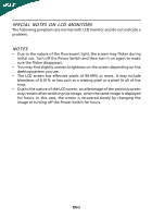
The following symptoms are normal with LCD monitor and do not indicate a problem. NOTES • Due to the nature of the fluorescent light, the screen may flicker during initial use. Turn off the Power Switch and then turn it - Acer G195WL | User Manual - Page 3
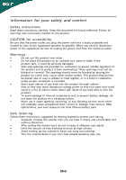
short current or damage rotor devices, HDD, Optical drive, and even exposure risk from lithium battery pack. Safe listening Follow these instructions, suggested by hearing experts,to protect your earing. • Gradually increase the volume until you can hear it clearly and comfortably and - Acer G195WL | User Manual - Page 4
performance, indicating a need for service • the product does not operate normally after following the operating instructions Note: Adjust only those zone Find your comfort zone by adjusting the viewing angle of the monitor, using a footrest, or raising your sitting height to achieve maximum - Acer G195WL | User Manual - Page 5
keyboard and mouse properly and within comfort able reach • if you view your monitor more than your documents, place the display at the center of your desk websites: Worldwide: http://www.acer-group.com/public/Sustainability/sustainability01.htm http://www.acer-group.com/public/Sustainability/ - Acer G195WL | User Manual - Page 6
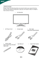
when you unpack the box, and save the packing materials in case you will need to ship or transport the monitor in future. • LCD Monitor • AC Power Cord • D-Sub Cable • DVI Cable (Only Dual-Input Model) • Audio Cable (Only Audio-Input Model) • (Optional) User Manual • Quick Start Guide EN-5 - Acer G195WL | User Manual - Page 7
-- use a cloth to avoid scratching the screen. Install: Remove: Align the release button on the Depress the release button as bottom of the monitor with the indicated first before removing the corresponding base and follow the arrow direction slots on the bottom of the base. to remove it - Acer G195WL | User Manual - Page 8
CONNECTING THE POWER CORD • Check first to make sure that the power cord you use is the correct type required for your area. • This monitor has a universal power supply that allows operation in either 100/120V AC or 220/240 V AC voltage area. No user-adjustment is required. • Plug one - Acer G195WL | User Manual - Page 9
system if your system also supports DDC protocol. The DDC (Display Data Channel) is a communication protocol through which the monitor automatically informs the host system about its capabilities, for example, supported resolutions and corresponding timing. The monitor supports DDC2B standard. EN-8 - Acer G195WL | User Manual - Page 10
1 10 6 15 11 15-Pin Color Display Signal Cable PIN NO. 1. 2. 3. 4. 5. 6. 7. 8. DESCRIPTION Red Green Blue Monitor Ground Self Test R-Ground G-Ground B-Ground PIN NO. 9. 10. 11. 12. 13. 14. 15. DESCRIPTION +5V Logic Ground Monitor Ground DDC-Serial Data H-Sync V-Sync DDC-Serial Clock EN-9 - Acer G195WL | User Manual - Page 11
24-Pin Color Display Signal Cable* PIN Meaning PIN 1. TMDS Data2- 13. 2. TMDS Data2+ 14. 3. TMDS Data 2/4 Shield 15. 4. NC 16. 5. NC 17. 6. DDC Clock 18. 7. DDC Data 19. 8. NC 20. 9. TMDS Data1- 21. 10. TMDS Data1+ 22. 11. TMDS Data 1/3 Shield 23. 12. NC 24. - Acer G195WL | User Manual - Page 12
Standard Timing Table Mode 1 Resolution 640 x 480 60 Hz 2 640 x 480 72 Hz 3 4 MAC 5 VESA 6 SVGA 7 SVGA 640 x 480 640 x 480 720x400 800 x 600 800 x 600 75 Hz 66.66 - Acer G195WL | User Manual - Page 13
to the monitor, then to a properly grounded AC outlet. 4. Power-ON Monitor and Computer Power-ON the monitor first, then power-ON the computer. This sequence is very important. 5. If the monitor still does not function properly, please refer to the troubleshooting section to diagnose the problem. EN - Acer G195WL | User Manual - Page 14
accessed settings. Empowering: Press the Empowering Key to open the Acer eColor Management OSD and access the scenario modes. AUTO Auto Adjust select from different video sources that may be connected to your monitor. (a) VGA input (b) DVI input (c) HDMI input As you cycle through the sources you - Acer G195WL | User Manual - Page 15
eColor Management Operation instructions Step 1: Press " " Key to open the Acer eColor Management OSD and access the scenario modes Step 2: Press " " or " " to select the mode Step 3: Press " Adjust/Exit " Key to confirm the mode and - Acer G195WL | User Manual - Page 16
: The following content is for general reference only. Actual product specifications may vary. The OSD can be used for adjusting the settings of your LCD Monitor. Press the MENU key to open the OSD. You can use the OSD to adjust the picture quality, OSD Timeout and general settings. For advanced - Acer G195WL | User Manual - Page 17
Adjusting the OSD Timeout 1 Press the MENU key to bring up the OSD. 2 Using the directional keys, select OSD from the on screen display. Then navigate to the feature you wish to adjust. EN-16 - Acer G195WL | User Manual - Page 18
Adjusting the setting 1 Press the MENU key to bring up the OSD. 2 Using the / keys, select Setting from the OSD. Then navigate to the feature you wish to adjust. Use the to Enter to the item page. 3 The Setting menu can be used to adjust the screen Menu Language and other important settings. EN-17 - Acer G195WL | User Manual - Page 19
Product information 1440 x 900 H: 67KHz V: 60Hz VGA Input S/N:ETL53091326350380B3742 1 Press the MENU key to bring up the OSD. 2 Using the / keys, select Information from the OSD. Then the basic information of LCD monitor will show up for current input. EN-18 - Acer G195WL | User Manual - Page 20
LCD monitor for servicing, please check the troubleshooting list below to see if you can self-diagnose the problem. (VGA Mode) Problems Current OSD, in case of missing full-screen size image, please select other resolution or other vertical refresh timing. · Wait for a few seconds after - Acer G195WL | User Manual - Page 21
(DVI Mode) Problems Current Status Remedy LED ON · Using OSD, adjust brightness and contrast to maximum or reset to their default settings. LED OFF · Check the power switch. No Picture · Check if AC power cord is properly connected to the monitor. LED displays amber color · Check if video - Acer G195WL | User Manual - Page 22
SA Via Cantonale, Centro Galleria 2 6928 Manno Switzerland Hereby declare that: Product: Trade Name: Model Number: SKU Number: LCD Monitor Acer G195WL G195WL xxxxxx ("x" = 0~9, a ~ z, A ~ Z or Blank) Is compliant with the essential requirements and other relevant provisions of the following EC - Acer G195WL | User Manual - Page 23
/Importer is responsible for this declaration: Product: Trade Name: Model Number: SKU Number: LCD Monitor Acer G195WL G195WL xxxxxx ("x" = 0~9, a ~ z, A ~ Z or Blank) Name of Responsible Party: Acer America Corporation Address of Responsible Party: 333 West San Carlos St. San Jose, CA 95110
-
 1
1 -
 2
2 -
 3
3 -
 4
4 -
 5
5 -
 6
6 -
 7
7 -
8
-
9
-
10
-
11
-
12
-
13
-
14
-
15
-
16
-
17
-
18
-
19
-
20
-
21
-
22
-
23
 |
 |

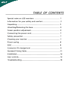
TABLE OF CONTENTS
Special notes on LCD monitors
..................................................
1
Information for your safety and
comfort
..................................
2
Unpacking
...................................................................................
5
Attaching/Removing the base
....................................................
6
Screen position adjustment
........................................................
6
Connecting the power cord
........................................................
7
Safety precaution
.......................................................................
7
Cleaning your monitor
...............................................................
7
Power saving
...............................................................................
8
DDC
..............................................................................................
8
Connector Pin Assignment
.........................................................
9
Standard Timing Table
..................................................................
11
Installation
.....................................................................................
12
User controls
..................................................................................
13
Troubleshooting
............................................................................
19