Acer P215 User Manual
Acer P215 Manual
 |
View all Acer P215 manuals
Add to My Manuals
Save this manual to your list of manuals |
Acer P215 manual content summary:
- Acer P215 | User Manual - Page 1
and comfort 2 Unpacking 5 Attaching/Removing the base 6 Screen position adjustment 6 Connecting the power cord 7 Safety precaution 7 Cleaning your monitor 7 Power saving 8 DDC 8 Connector Pin Assignment 9 Standard Timing Table 11 Installation 12 User controls 13 Troubleshooting 19 - Acer P215 | User Manual - Page 2
SPECIAL NOTES ON LCD MONITORS The following symptoms are normal with LCD monitor and do not indicate a problem. NOTES · Due to the nature of the fluorescent light, the screen may flicker during initial use. Turn off the Power Switch and then turn it - Acer P215 | User Manual - Page 3
Do not place this product on an unstable cart, stand or table. If the product falls, it could be as they may touch dangerous voltage points or short-out parts that could result in a fire or electric shock. battery pack. Safe listening Follow these instructions, suggested by hearing experts,to - Acer P215 | User Manual - Page 4
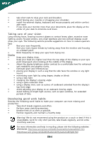
angle of the monitor, using a footrest, or raising your sitting height to achieve maximum comfort. Observe the following tips: • refrain from staying too long in one fixed posture • avoid slouching forward and/or leaning backward • stand up and walk around regularly to remove the strain on - Acer P215 | User Manual - Page 5
and within comfort able reach • if you view your monitor more than your documents, place the display at to an awkward viewing angle. • Avoid looking at bright light sources, such as open windows, for extended acer-group.com/public/Sustainability/sustainability01.htm http://www.acer-group.com - Acer P215 | User Manual - Page 6
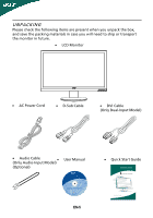
case you will need to ship or transport the monitor in future. · LCD Monitor · AC Power Cord · D-Sub Cable · DVI Cable (Only Dual-Input Model) · Audio Cable (Only Audio-Input Model) · (Optional) User Manual P/N:MU.LHR00.001 P215H 2009 EN-5 · Quick Start Guide P215H LCD monitor Quick Start - Acer P215 | User Manual - Page 7
: Align the base with the stand and push the base towards the top of the monitor. Remove: Depress the release hooks as indicated first before removing the base and follow the arrow direction to remove it. SCREEN POSITION ADJUSTMENT In oder to optimize the best viewing position, you can adjust the - Acer P215 | User Manual - Page 8
. · This monitor has a universal power supply that allows operation in either 100/120V AC or 220/240 V AC voltage area. No user-adjustment is required wire and plug rated 10 A/125 V. · For unit using at 220/240 V AC (outside of U.S.): Use a Cord Set consisting of H05VV-F cord and plug rated 10 A, 250 - Acer P215 | User Manual - Page 9
system if your system also supports DDC protocol. The DDC (Display Data Channel) is a communication protocol through which the monitor automatically informs the host system about its capabilities, for example, supported resolutions and corresponding timing. The monitor supports DDC2B standard. EN-8 - Acer P215 | User Manual - Page 10
. 9. 10. 11. 12. 13. 14. 15. DESCRIPTION +5V Logic Ground Monitor Ground DDC-Serial Data H-Sync V-Sync DDC-Serial Clock 19-pin color display signal cable* 1917151311 9 7 5 3 1 1816141210 8 6 4 2 PIN No. Clock- 14 Reserved (N.C. on device) 16 SDA 18 +5V Power * only for certain models EN-9 - Acer P215 | User Manual - Page 11
24-Pin Color Display Signal Cable* PIN Meaning PIN Meaning 1. TMDS Data2- 13. NC 2. TMDS Clock 18. TMDS Data0+ 7. DDC Data 19. TMDS Data 0/5 Shield 8. NC 20. NC 9. TMDS Data1- 21. NC 10. TMDS Data1+ 22. TMDS Clock Shield 11. TMDS Data 1/3 Shield 23. TMDS Clock+ 12. - Acer P215 | User Manual - Page 12
Standard Timing Table Mode Resolution 1 VGA 640x480 60 Hz 2 MAC 640x480 66.66 Hz 3 VESA 720x400 70 Hz 4 SVGA 800x600 56 Hz 5 SVGA 800x600 60 Hz 6 XGA 1024x768 60 Hz 7 - Acer P215 | User Manual - Page 13
grounded AC outlet. 4. Power-ON Monitor and Computer Power-ON the monitor first, then power-ON the computer. This sequence is very important. 5. If the monitor still does not function properly, please refer to the troubleshooting section to diagnose the problem. HDMI (optional) HDMI (optional) EN-12 - Acer P215 | User Manual - Page 14
the OSD menu. Volume Up / Down Press to adjust volume (Only Audio-Input Model)(Optional) INPUT Input Key Use Input key to select from different video sources that may be connected to your monitor. (a) VGA input (b) DVI input (c) HDMI input As you cycle through the sources you will see the following - Acer P215 | User Manual - Page 15
eColor Management Operation instructions Step 1: Press " " Key to open the Acer eColor Management OSD and access the scenario lay mode capability N/A Grahpic mode Enhances colors and emphasize fine detail. Pictures and photographs appear in vibrant colors with sharp detail. N/A Movie mode - Acer P215 | User Manual - Page 16
Note: The following content is for general reference only. Actual product specifications may vary. The OSD can be used for adjusting the settings of your LCD Monitor. Press the MENU key to open the OSD. You can use the OSD to adjust the picture quality, OSD position and general settings. For - Acer P215 | User Manual - Page 17
Adjusting the OSD position 1 Press the MENU key to bring up the OSD. 2 Using the directional keys, select OSD from the on screen display. Then navigate to the feature you wish to adjust. EN-16 - Acer P215 | User Manual - Page 18
Adjusting the setting 1 Press the MENU key to bring up the OSD. 2 Using the / keys, select Setting from the OSD. Then navigate to the feature you wish to adjust. 3 The Setting menu can be used to adjust the screen Menu Language and other important settings. EN-17 - Acer P215 | User Manual - Page 19
Product information 1 Press the MENU key to bring up the OSD. 2 Using the / keys, select Information from the OSD. Then the basic information of LCD monitor will show up for current input. EN-18 - Acer P215 | User Manual - Page 20
LCD monitor for servicing, please check the troubleshooting list below to see if you can self-diagnose the problem. (VGA Mode) Problems is properly connected to the monitor. LED displays amber color · Check if video signal cable is properly connected at the back of monitor. · Check if the power - Acer P215 | User Manual - Page 21
/HDMI mode) Problems Current Status Remedy LED ON · Using OSD, adjust brightness and contrast to maximum or reset to their default settings. LED OFF · Check the power switch. No Picture · Check if AC power cord is properly connected to the monitor. LED displays amber color · Check if video - Acer P215 | User Manual - Page 22
: [email protected] And, Acer Europe SA Via Cantonale, Centro Galleria 2 6928 Manno Switzerland Hereby declare that: Product: Trade Name: Model Number: Series Model Type: SKU Number: LCD Monitor Acer P215H P215Hxxxx 2009. Easy Lai /Manager Regulation, Acer Inc. EN-21 Aug. 7, 2009 Date - Acer P215 | User Manual - Page 23
www.acer.com Federal Communications Commission Declaration of Conformity This device complies with Part 15 of the FCC Rules. Operation : Product Name: Main Model Number: Series Model Number: 21.5"W LCD Monitor P215Hxxxx P215Hxxxx Name of Responsible Party: Acer America Corporation Address of
-
 1
1 -
 2
2 -
 3
3 -
 4
4 -
 5
5 -
 6
6 -
 7
7 -
8
-
9
-
10
-
11
-
12
-
13
-
14
-
15
-
16
-
17
-
18
-
19
-
20
-
21
-
22
-
23
 |
 |

TABLE OF CONTENTS
Special notes on LCD monitors
..................................................
1
Information for your safety and
comfort
..................................
2
Unpacking
...................................................................................
5
Attaching/Removing the base
....................................................
6
Screen position adjustment
........................................................
6
Connecting the power cord
.......................................................
7
Safety precaution
.......................................................................
7
Cleaning your monitor
...............................................................
7
Power saving
...............................................................................
8
DDC
..............................................................................................
8
Connector Pin Assignment
.........................................................
9
Standard Timing Table
..................................................................
11
Installation
.....................................................................................
12
User controls
..................................................................................
13
Troubleshooting
............................................................................
19