Acer TravelMate 2000 TravelMate 2000/2500 Service Guide
Acer TravelMate 2000 Manual
 |
View all Acer TravelMate 2000 manuals
Add to My Manuals
Save this manual to your list of manuals |
Acer TravelMate 2000 manual content summary:
- Acer TravelMate 2000 | TravelMate 2000/2500 Service Guide - Page 1
Acer TravelMate 2000/2500 Series Service Guide PRINTED IN TAIWAN - Acer TravelMate 2000 | TravelMate 2000/2500 Service Guide - Page 2
Revision History Please refer to the table below for the updates made on TravelMate 2000/2500 service guide. Date 2004/04/21 Chapter Chapter 1 Updates Add description about modem chipset on page 21 II - Acer TravelMate 2000 | TravelMate 2000/2500 Service Guide - Page 3
, manual or otherwise, without the prior written permission of Acer Incorporated. Disclaimer The information in this guide is subject to change without notice. Acer Incorporated makes no representations or warranties, either expressed or implied, with respect to the contents hereof and specifically - Acer TravelMate 2000 | TravelMate 2000/2500 Service Guide - Page 4
additional information related to the current topic. Alerts you to any damage that might result from doing or not doing specific actions. Gives precautionary measures to avoid possible hardware or software problems. Reminds you to do specific actions relevant to the accomplishment of procedures. IV - Acer TravelMate 2000 | TravelMate 2000/2500 Service Guide - Page 5
card, modem, or extra memory capability). These LOCALIZED FEATURES will NOT be covered in this generic service guide. In such cases, please part number change is made, it will not be noted in the printed Service Guide. For ACER AUTHORIZED SERVICE PROVIDERS, your Acer office may have a DIFFERENT part - Acer TravelMate 2000 | TravelMate 2000/2500 Service Guide - Page 6
VI - Acer TravelMate 2000 | TravelMate 2000/2500 Service Guide - Page 7
46 BIOS Flash Utility 47 Chapter 3 Machine Disassembly and Replacement 48 General Information 49 Before You Begin 49 Disassembly Procedure Flowchart 50 Removing the Battery 52 Removing the Memory Module 53 Removing the Wireless LAN Board and the Modem Board 54 Removing the Hard Disk Drive - Acer TravelMate 2000 | TravelMate 2000/2500 Service Guide - Page 8
75 Memory check 76 Power System Check 76 Touchpad Check 78 Power-On Self-Test (POST) Error Message 79 Index of Error Messages 80 Index of Symptom-to-FRU Error Message 83 Intermittent Problems 86 Undetermined Problems 87 How to Build NAPP Master Hard Disc Drive 88 CD to Disk Recovery 88 - Acer TravelMate 2000 | TravelMate 2000/2500 Service Guide - Page 9
2500) and Intel® Celeron® (for TravelMate 2000) processor, 2.40 GHz or above T Intel® Hyper-ThreadingTM technology T 256/512 MB of DDR333 SDRAM standard, upgradeable to 2048MB with dual soDIMM modules T 30 GB and above high-capacity, Enhanced-IDE hard disc drive T Advanced Configuration Power - Acer TravelMate 2000 | TravelMate 2000/2500 Service Guide - Page 10
T Upgrageable memory modules I/O Ports T T T T T T T T T T One Type III or two Type II PC Card slot One RJ-11 modem jack (V.92, 56K) One RJ-45 network jack One - Acer TravelMate 2000 | TravelMate 2000/2500 Service Guide - Page 11
BAT CONN 43 AD CONN 43 INVERTER 14 Power Button 35 E SYSTEM DC/DC TPS51020DBT 38 +VCC_CORE 1.3V 44A +VID 1.2V 0.3A MAXIM CHARGER MAX1909 41 INPUTS OUTPUTS BT+ 18V 4.0A DCBATOUT 2 PS/2 Debug 33 con 33 D L5: GND L6: Signal 4 1 Acer Inc. 8F, 88, Sec.1, Hsin Tai Wu Rd., Hsichih, Taipei - Acer TravelMate 2000 | TravelMate 2000/2500 Service Guide - Page 12
Bridge 17 Fan Connector 18 Second Fan Connector 19 Touchpad Cable Connector 20 HDD Connector 21 Keyboard Connector 22 Speaker Cable Connector 23 Optical Drive Connector 24 South Bridge 25 RTC Battery Connector 26 Launch Board Cable Connector 27 SW5 (Please see Chapter 5 for its settings) 28 PCMCIA - Acer TravelMate 2000 | TravelMate 2000/2500 Service Guide - Page 13
Bottom View 1 Wireless LAN Card Connector 2 Modem Board Connector 3 Modem Cable Connector 4 IEEE 1394 Port 5 FIR Port 6 DIMM Socket 1 7 DIMM Socket 2 8 Chapter 1 5 - Acer TravelMate 2000 | TravelMate 2000/2500 Service Guide - Page 14
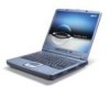
Display screen Status indicators Power button Launch Keys Palmrest Click buttons (left, center and right) Touchpad Keyboard Ventilation Slot Description Also and components. Turns on the computer power. Buttons for launching frequently used programs. Comfortable support area for your hands when you - Acer TravelMate 2000 | TravelMate 2000/2500 Service Guide - Page 15
from teh drive. Lights up when the optical drive is active. Ejects the optical drive tray when the computer is turned off. There is a mechancial eject button on the CD-ROM or DVD-ROM drive. Simply insert the tip of a pen or paperclip and push to eject the tray. Delivers stereo audio output. Chapter - Acer TravelMate 2000 | TravelMate 2000/2500 Service Guide - Page 16
Right Panel # 1 2 3 Icon Item/ Port Speaker Ventilation slots Security keylock Description Delivers stereo audio output. Enable the computer to stay cool, even after prolonged use. Connects to a Kensington-compatible computer security lock. 8 Chapter 1 - Acer TravelMate 2000 | TravelMate 2000/2500 Service Guide - Page 17
l # 1 2 3 4 5 6 7 8 9 Icon Port Power Jack Description Connects to an AC adapter Parallel port Connects to a parallel device (e.g., parallel printer). Ventilation slot /Line-Out/ Headphone jack Connects to audio line-out devices (e.g., speakers, headphone). Line-in/Mic-in jack Accepts - Acer TravelMate 2000 | TravelMate 2000/2500 Service Guide - Page 18
Bottom Panel # 1 2 3 Item Battery bay Battery release latch Memory compartment Description Houses the computer's battery pack. Unlatches the battery to remove the battery pack. Houses the computer's main memory. 10 Chapter 1 - Acer TravelMate 2000 | TravelMate 2000/2500 Service Guide - Page 19
2 Power Lights when the computer is on. 3 Sleep Lights when the computer enters Standby mode and blinks when it enters into or resumes from hibernation mode. 4 Media Activity Lights when the floppy drive, hard disk or optical drive is active. 5 Battery Charge Lights when the battery is - Acer TravelMate 2000 | TravelMate 2000/2500 Service Guide - Page 20
of your computer is closed, 2 easy-to-read icons are shown, indicating which state or feature is enabled or disabled. # Icon Function Description 1 Power Lights up when the computer is on. 2 Sleep Lights when the computer enters Standby mode and blinks when it enters into or resumes from - Acer TravelMate 2000 | TravelMate 2000/2500 Service Guide - Page 21
has full-sized keys and an embedded keypad, separate cursor keys, two Windows keys and twelve function keys. Special keys Lock keys The keyboard has three lock keys which you can toggle on and off. Lock key Caps Lock @ Num Lock (Fn-F11) ] Scroll Lock (Fn-F12) [ Description When @ - Acer TravelMate 2000 | TravelMate 2000/2500 Service Guide - Page 22
, cursor-control key symbols are not printed on the keys. Desired access Number keys on embedded keypad Cursor-control keys on embedded keypad Main keyboard keys Num lock on Type numbers in a normal manner. Hold Shift while using cursor-control keys. Hold Fn while typing letters on embedded keypad - Acer TravelMate 2000 | TravelMate 2000/2500 Service Guide - Page 23
keys The keyboard has two keys that perform Windows-specific functions. Keys Windows logo key Application key Description Start button. Combinations with this key perform shortcut functions. Below are a few examples: + Tab (Activates next taskbar button) + E (Explores My - Acer TravelMate 2000 | TravelMate 2000/2500 Service Guide - Page 24
and brightness, volume output and the BIOS Utility. To activate hot keys, press notebook configuration utility. Power Management Scheme Toggle Sleep Switches between the power management scheme used by the computer (function available if supported backlight off to save power. Press any key to return - Acer TravelMate 2000 | TravelMate 2000/2500 Service Guide - Page 25
-International or United Kingdom or if you have a keyboard with a European layout, you can type the Euro symbol on your keyboard. NOTE: for US keyboard users: The keyboard layout is set when you first set up Windows. For the Euro symbol to work, the keyboard layout has to be set to United States - Acer TravelMate 2000 | TravelMate 2000/2500 Service Guide - Page 26
the top of the keyboard are six buttons. These buttons are called lauch keys. They are designated as mail button, Web browser button, P1, P2, Bluetooth and Wireless buttons. The Wireless and Bluetooth buttons cannot be set by the user. To set the other four launch keys, run the Acer Launch Manager - Acer TravelMate 2000 | TravelMate 2000/2500 Service Guide - Page 27
Specifications and Configurations System Board Major Chips Item System core logic Super I/O controller Audio controller Video controller Hard disk drive controller Keyboard Processor (for TravelMate 2500) CPU type Item CPU package CPU core voltage CPU I/O voltage Specification Intel® Pentium® - Acer TravelMate 2000 | TravelMate 2000/2500 Service Guide - Page 28
Supported protocols BIOS password control Second Level Cache Item Cache controller Cache size 1st level cache control 2nd level cache control Cache scheme control Specification ACPI 1.0b, SMBIOS 2.3, PCI 2.2, Boot Block, PXE 2.0, Mobile PC2001, Hard Disk Password, INT 13h Extensions, PCI Bus Power - Acer TravelMate 2000 | TravelMate 2000/2500 Service Guide - Page 29
56K V.90/V.92MDC RJ11 Rear side Floppy Disk Drive Interface Item Vendor & model name Floppy Disk Specifications Media recognition Sectors/track Tracks Data transfer rate (Kbit/s) Rotational speed (RPM) Read/write heads Encoding method Power Requirement Input Voltage (V) Mitsumi D353G 4515 MCI JU - Acer TravelMate 2000 | TravelMate 2000/2500 Service Guide - Page 30
. Hard Disk Drive Interface Item Vendor & Model Name HGST Moraga IC25N030ATMR04 Fujitsu s) 100 MB/Sec DC Power Requirements Voltage tolerance 5 +/- 5% 350 100 MB/Sec 5 +/- 5% 350 100MB/Sec CD-ROM Interface Items Vendor & Model Name Performance Specification Brust Data Transfer rate Access - Acer TravelMate 2000 | TravelMate 2000/2500 Service Guide - Page 31
CD-ROM Interface Items Rotation speed Data Buffer Capacity Interface Applicable disc format Loading mechanism Power Requirement Input Voltage Specification 5100 rpm for QSI 5400 rpm for Mitsumi 24X CAV mode 128 KB (built-in) Compliant to ATA/ATAPI-6 QSI: CD-DA, CD-ROM Mode-1, - Acer TravelMate 2000 | TravelMate 2000/2500 Service Guide - Page 32
Power Requirement Input Voltage Combo Drive Interface Item Vendor & model name Performance Specification Specification average max 512 kBytes IDE DVD: DVD-5, DVD-9, DVD-10, DVD-R (3.95G), DVD-RAM (2.6G), DVDRAM (4.7G) CD: CD-Audio, CD-ROM (mode 1 and mode 2), CD-ROM XA (mode 2, form 1 and - Acer TravelMate 2000 | TravelMate 2000/2500 Service Guide - Page 33
Combo Drive Interface Item Transfer rate (KB/sec) Buffer rate , DVD-R, DVD-RW (Ver.1.1), DVD-VIDEO, DVD-RAM (2.6GB, 4.7GB) 15 degree (Any direction) 128X129X12.7mm (WXDXH) (except protrusion) 200g+- 10g Soft Eject (with emergency eject hole) Specification Liteon DVD-Dual SDW-431S CD-DA, CD-TEXT, - Acer TravelMate 2000 | TravelMate 2000/2500 Service Guide - Page 34
Item Specification Disc Diameter MHz or above) OS MS-Windows 90/ME/2000/XP/NT 4.0 Memory Min. 128MB required Hard Disk Empty Storage Capacity:100 RW: DPP Wave length: CD: 785+/- 5 nm DVD: 650+/- 15 nm Output power: Read CD: 1.5 mw max@objective lens DVD: 1.0 mw max Write CD: 65 - Acer TravelMate 2000 | TravelMate 2000/2500 Service Guide - Page 35
Item Loading mechanism Audio Interface Item Audio Controller Audio onboard or optional Mono or Stereo Resolution Compatibility Mixed sound source Voice channel Sampling rate Internal microphone Internal speaker / Quantity Supports PnP DMA channel Supports PnP IRQ Specification Manual load/DC - Acer TravelMate 2000 | TravelMate 2000/2500 Service Guide - Page 36
Yes Yes (IRQ17) Specification Keyboard Item Keyboard controller Keyboard vendor & model name Total number of keypads Windows 95 keys Internal & external keyboard work simultaneously Specification Mitsubishi LPC keyboard controller M38857 API 84-/85-/88- key Yes Yes Battery Item Vendor & model - Acer TravelMate 2000 | TravelMate 2000/2500 Service Guide - Page 37
Nominal Input Voltage VDD Typical Power Consumption (watt) Weight Physical Size(mm) Electrical Interface Support Color Viewing Angle (degree) 550 317.3x242.0x6.0 1 channel LVDS 2 channel LVDS 262K colors (RGB 6bit data driver) N/A 250 6/17 +3.3V Typ. 4.4 505 317.3x242.0x5.7 N/A 262,144 colors LG: - Acer TravelMate 2000 | TravelMate 2000/2500 Service Guide - Page 38
Input Voltage VDD Typical Power Consumption (watt) Weight Physical Size(mm) Electrical Interface Support Color Hannstar HSD150PX14 14.1 inches 285.7x214.3 1024x768 XGA 0.279x0.279 R.G.B. Vertical Stripe Normally White 150 N/A 250 20/30 3.3V 3.96 445 298.5x226.7x5.2 1 channel LVDS 262,144 CMO - Acer TravelMate 2000 | TravelMate 2000/2500 Service Guide - Page 39
50 -20 to +60 45/45 15/35 0 to +50 -20 to +60 AC Adapter Item Vendor & model name Input Voltage Low Range High Range Input current Nominal frequency (Hz) Voltage Primary to secondary Ground leakage current Liton, 135W power supply Specification 90(min.)/137(max.)/100-127(nominal) 180(min.)/265 - Acer TravelMate 2000 | TravelMate 2000/2500 Service Guide - Page 40
mode. Display Standby Mode Keyboard, built-in touchpad, and an external PS/2 pointing device are idle for a specified period. Hard Disk Standby Mode Hard disk is idle within a specified period of time. Phenomenon T All power shuts off T The display shuts off T Hard disk drive is in standby mode - Acer TravelMate 2000 | TravelMate 2000/2500 Service Guide - Page 41
Chapter 1 33 - Acer TravelMate 2000 | TravelMate 2000/2500 Service Guide - Page 42
, and you do not need to run this utility. However, if you encounter configuration problems, you may need to run Setup. Please also refer to Chapter 4 Troubleshooting when problem arises. To activate the BIOS Utility, press m during POST (when "Press to enter Setup" message is prompted on - Acer TravelMate 2000 | TravelMate 2000/2500 Service Guide - Page 43
any changes made and exit the BIOS Setup Utility. NOTE: You can change the value of a parameter if it is enclosed in square brackets. Navigation keys for a particular menu are shown on the bottom of the screen. Help for parameters are found in the Item Specific Help part of the screen. Read this - Acer TravelMate 2000 | TravelMate 2000/2500 Service Guide - Page 44
Number Serial Number UUID Number Description Shows floppy drive type informaiton. Note: Aspre 1620, Extensa 2700, TravelMate 2500 and Extnesa 2500 series products do not have floppy disk drive; Extensa 2000 and TravelMate 2000 series have floppy disk drive. This field shows the model name of HDD - Acer TravelMate 2000 | TravelMate 2000/2500 Service Guide - Page 45
Main The Main screen displays a summary of your computer hardware information, and also includes basic setup parameters. It allows the user to specify standard IBM PC AT system parameters. NOTE: The screen above is for reference only. Actual values may differ. 37 Chapter 2 - Acer TravelMate 2000 | TravelMate 2000/2500 Service Guide - Page 46
Date System Memory Extended Memory VGA Memory Fast Boot Power on display power when AC is not present. The system will support an automatic dimming of the LCD backlight when the AC power is NOT available (running on battery power BIOS Setup Utility, this item will be disappeared. Chapter 2 38 - Acer TravelMate 2000 | TravelMate 2000/2500 Service Guide - Page 47
or above. The system will automatically hide this selection when detecting the CPU frequency is below 3.06G or the CPU does not support Hyper-Threading Technoloty. Enabled/Disabled Enables, disables or auto detects the infrared port. Disabled/Disabled/Auto Enables, disables or auto detects the - Acer TravelMate 2000 | TravelMate 2000/2500 Service Guide - Page 48
Parameter DMA channel Legacy USB Support Hard Disk Recovery Description Sets a DMA channel for the printer to operate in ECP mode. This parameter is enabled only if Mode is set to ECP. Enables, disables USB interface devices support. (Enable for use with a non-USB aware Operating System such as DOS - Acer TravelMate 2000 | TravelMate 2000/2500 Service Guide - Page 49
Security The Security screen contains parameters that help safeguard and protect your computer from unauthorized use. 41 Chapter 2 - Acer TravelMate 2000 | TravelMate 2000/2500 Service Guide - Page 50
or Enabled NOTE: When you are prompted to enter a password, you have three tries before the system halts. Don't forget your password. If you forget your password, you may have to return your notebook computer to your dealer to reset it. Setting a Password Follow these steps as you set the user or - Acer TravelMate 2000 | TravelMate 2000/2500 Service Guide - Page 51
the BIOS Setup Utility. Changing a Password 1. Use the w and y keys to highlight the Set Supervisor Password parameter and press the e key. The Set Password box appears: 2. Type the current password in the Enter Current Password field and press e. 3. Type a password in the Enter New Password field - Acer TravelMate 2000 | TravelMate 2000/2500 Service Guide - Page 52
If the current password entered does not match the actual current password, the screen will show you the Setup Warning. If the new password and confirm new password strings do not match, the screen will display the following message. Chapter 2 44 - Acer TravelMate 2000 | TravelMate 2000/2500 Service Guide - Page 53
Boot This menu allows the user to decide the order of boot devices to load the operating system. Bootable devices includes the distette drive in module bay, the onboard hard disk drive and the CD-ROM in module bay. 45 Chapter 2 - Acer TravelMate 2000 | TravelMate 2000/2500 Service Guide - Page 54
Exit The Exit screen contains parameters that help safeguard and protect your computer from unauthorized use. The table below describes the parameters in this screen. Parameter Exit Saving Changes Exit Discarding Changes Load Setup Default Discard Changes Save Changes Description Exit System - Acer TravelMate 2000 | TravelMate 2000/2500 Service Guide - Page 55
a Crisis Recovery Diskette before you use the Phlash utility. NOTE: Do not install memory-related drivers (XMS, EMS, DPMI) when you use the Phlash. NOTE: Please use the AC adaptor power supply when you run the Phlash utility. If the battery pack does not contain enough power to finish BIOS flash - Acer TravelMate 2000 | TravelMate 2000/2500 Service Guide - Page 56
on how to disassemble the notebook computer for maintenance and troubleshooting. To disassemble the computer, TravelMate 240/250). Please refer to the disassembling procedures instead of the images. Some of the images below contain the parts used in TravelMate 240/250, but not in TravelMate 2000/2500 - Acer TravelMate 2000 | TravelMate 2000/2500 Service Guide - Page 57
General Information Before You Begin Before proceeding with the disassembly procedure, make sure that you do the following: 1. Turn off the power to the system and all peripherals. 2. Unplug the AC adapter and all power and signal cables from the system. 49 Chapter 3 - Acer TravelMate 2000 | TravelMate 2000/2500 Service Guide - Page 58
sequence and instructs you on the components that need to be removed during servicing. For example, if you want to remove the main board, you must first remove the keyboard, then disassemble the inside assembly frame in that order. Start Battery HDD Module G*2 HDD HDD Holder *2 DIMM Cover Memory - Acer TravelMate 2000 | TravelMate 2000/2500 Service Guide - Page 59
LCD Module 4 LCD Cushions E*4 LCD Bezel L*1 Inverter L*4 LCD LCD Panel LCD Coaxial Cable H*8 for 14.1" H*6 for 15.0" LCD Brackets Screw List Item A B C D E F G H I J Description SCREW MAC FLAT M2.5*L4 NI NYLOK (86.00123.630) SCREW M2.0*L10 NYLOK(86.9A352.100) SCREW M2*3 NYLON 1JMCPC420325(86 - Acer TravelMate 2000 | TravelMate 2000/2500 Service Guide - Page 60
Removing the Battery 1. To remove the battery, push the battery release latch. 2. Then slide the battery out from the machine. Chapter 3 52 - Acer TravelMate 2000 | TravelMate 2000/2500 Service Guide - Page 61
Removing the Memory Module 1. See "Removing the Battery" on page 52. 2. To remove the memory module from the machine, first remove the two screws holding the dimm cover. 3. Remove the dimm cover. 4. Pop up the memory. 5. Then remove the memory. 53 Chapter 3 - Acer TravelMate 2000 | TravelMate 2000/2500 Service Guide - Page 62
Removing the Wireless LAN Board and the Modem Board 1. See "Removing the Battery" on page 52. 2. To remove the wireless LAN board, first remove the two screws holding the modem cover. 3. Remove the modem cover from the machine. 4. - Acer TravelMate 2000 | TravelMate 2000/2500 Service Guide - Page 63
" on page 52. 2. To remove the hard disk drive, pull the hard disk dirve carefully. 3. Then take the hard disk drive out of the main unit. Disassembling the Hard Disk Drive Module 1. See "Removing the Battery" on page 52. 2. See "Removing the Hard Disk Drive Module" on page 55. 3. Remove the two - Acer TravelMate 2000 | TravelMate 2000/2500 Service Guide - Page 64
Removing the LCD Module Removing the Middle Cover 1. See "Removing the Battery" on page 52. 2. To remove the middle cover, first use a plastic cover off the main unit. . Removing the Launch Board 1. See "Removing the Battery" on page 52. 2. See "Removing the Middle Cover" on page 56. Chapter 3 56 - Acer TravelMate 2000 | TravelMate 2000/2500 Service Guide - Page 65
3. Remove the two screws and then detach the launch board from the middle cover. Removing the LCD Module 1. See "Removing the Battery" on page 52. 2. See "Removing the Middle Cover" on page 56. 3. See "Removing the Launch Board" on page 56. 4. Remove the screw that fastens the - Acer TravelMate 2000 | TravelMate 2000/2500 Service Guide - Page 66
Chapter 3 58 - Acer TravelMate 2000 | TravelMate 2000/2500 Service Guide - Page 67
the LCD bezel from the LCD module. Removing the Inverter Board (15" LCD) 1. See "Removing the Battery" on page 52. 2. See "Removing the Middle Cover" on page 56. 3. See "Removing the board. 7. Disconnect the LCD power cable then disconnect the inverter cable from the inverter board. 59 Chapter 3 - Acer TravelMate 2000 | TravelMate 2000/2500 Service Guide - Page 68
cable well to the LCD panel as the picture below shows when you reassemble the LCD module. Removing the 15" TFT LCD 1. See "Removing the Battery" on page 52. 2. See "Removing the Middle Cover" on page 56. 3. See "Removing the Launch Board" on page 56. 4. See "Removing the LCD Module" on - Acer TravelMate 2000 | TravelMate 2000/2500 Service Guide - Page 69
right bracket. 9. Remove the four screws holding the left LCD bracket. Then remove the left bracket.. Removing the LCD Coaxial Cable 1. See "Removing the Battery" on page 52. 2. See "Removing the Middle Cover" on page 56. 3. See "Removing the Launch Board" on page 56. 4. See "Removing the LCD Module - Acer TravelMate 2000 | TravelMate 2000/2500 Service Guide - Page 70
2. See "Removing the Middle Cover" on page 56. 3. See "Removing the Launch Board" on page 56. 4. See "Removing the LCD Module" on page 57. 5. See "Removing the LCD Bezel" on page 59. 6. See "Removing the Inverter Board (15" LCD)" on page 59. 7. See "Removing the 15" TFT LCD" on page 60. 8. Remove - Acer TravelMate 2000 | TravelMate 2000/2500 Service Guide - Page 71
as the pticute shows. 4. Use a plastic tweezers or a plastic flat screwdriver to disconnect the keyboard cable from the main board carefully, then remove the keyboard. Removing the RTC Battery 1. See "Removing the Battery" on page 52. 2. See "Removing the Middle Cover" on page 56. 3. See "Removing - Acer TravelMate 2000 | TravelMate 2000/2500 Service Guide - Page 72
module. 6. Then remove the thermal module. Removing the Processor 1. See "Removing the Battery" on page 52. 2. See "Removing the Middle Cover" on page 56. 3. See "Removing the Keyboard" on page 63. 4. See "Removing the RTC Battery" on page 63. 5. See "Removing the Fan" on page 63. 6. See "Removing - Acer TravelMate 2000 | TravelMate 2000/2500 Service Guide - Page 73
Middle Cover" on page 56. 3. See "Removing the Keyboard" on page 63. 4. See "Removing the RTC Battery" on page 63. 5. See "Removing the Fan" on back to the socket. Removing the Upper Case Assemly 1. See "Removing the Keyboard" on page 63. 2. Disconnect the touchpad cable. 3. Remove the 5 screws - Acer TravelMate 2000 | TravelMate 2000/2500 Service Guide - Page 74
4. Then take the upper case assembly off the main unit. Removing the Touchpad Board 1. See "Removing the Battery" on page 52. 2. See "Removing the Middle Cover" on page 56. 3. See "Removing the Keyboard" on page 63. 4. See "Removing the Upper Case Assemly" on page 65. 5. To detach the touch pad - Acer TravelMate 2000 | TravelMate 2000/2500 Service Guide - Page 75
screws holding the VGA thermal plate then remove it. Removing the CPU Heatsink Plate 1. See "Removing the Battery" on page 52. 2. See "Removing the Middle Cover" on page 56. 3. See "Removing the Keyboard" on page 63. 4. See "Removing the Fan" on page 63. 5. See "Removing the Thermal Module" on page - Acer TravelMate 2000 | TravelMate 2000/2500 Service Guide - Page 76
hard.Then remove the ODD module from the lower case. NOTE: If you need to replace the ODD module only, you can remove the ODD module as the steps above. Removing the ODD Module(2) 1. See "Removing the Battery" on page 52. 2. See "Removing the Middle Cover" on page 56. 3. See "Removing the Keyboard - Acer TravelMate 2000 | TravelMate 2000/2500 Service Guide - Page 77
screws holding the HDD bracket, then remove the HDD bracket. Removing the Main Board 1. See "Removing the Battery" on page 52. 2. See "Removing the Middle Cover" on page 56. 3. See "Removing the Keyboard" on page 63. 4. See "Removing the Upper Case Assemly" on page 65. 5. See "Removing the Fan" on - Acer TravelMate 2000 | TravelMate 2000/2500 Service Guide - Page 78
board. Then detach the main board from the lower case carefully. Removing the DC Board 1. See "Removing the Battery" on page 52. 2. See "Removing the Middle Cover" on page 56. 3. See "Removing the Keyboard" on page 63. 4. See "Removing the Upper Case Assemly" on page 65. 5. See "Removing the Fan" on - Acer TravelMate 2000 | TravelMate 2000/2500 Service Guide - Page 79
screws to detach the I/O port bracket from the main board. Removing the PCMCIA Slot 1. See "Removing the Battery" on page 52. 2. See "Removing the Middle Cover" on page 56. 3. See "Removing the Keyboard" on page 63. 4. See "Removing the Upper Case Assemly" on page 65. 5. See "Removing the Fan" on - Acer TravelMate 2000 | TravelMate 2000/2500 Service Guide - Page 80
Removing the Speaker Set 1. See "Removing the Battery" on page 52. 2. See "Removing the Middle Cover" on page 56. 3. See "Removing the Keyboard" on page 63. 4. See "Removing the Upper Case Assemly" on page 65. 5. See "Removing the Fan" on page 63. 6. See "Removing the Thermal Module" on - Acer TravelMate 2000 | TravelMate 2000/2500 Service Guide - Page 81
System Upgrade Procedure Base Unit to Wireless Unit 1. Turn out the two screws fastening the modem cover then open the cover. 2. Connect the wirless antennae. 3. Insert the wireless LAN board to the wireless socket on the main board. 4. Close the modem cover and fasten the cover with the two screws. - Acer TravelMate 2000 | TravelMate 2000/2500 Service Guide - Page 82
Troubleshooting Use the following procedure as a guide for computer problems. NOTE: The diagnostic tests are intended to test only Acer products. Non-Acer symptom to determine which page to go to. Symptoms (Verified) Power failure. (The power indicator does not go on or stay on.) POST does not - Acer TravelMate 2000 | TravelMate 2000/2500 Service Guide - Page 83
Follow the instructions in the message window. If an error occurs, reconnect the connector on the System board. If the error still remains: 1. Reconnect the external diskette drive/CD-ROM module. 2. Replace the external diskette drive/CD-ROM module. 3. Replace the main board. Keyboard or Auxiliary - Acer TravelMate 2000 | TravelMate 2000/2500 Service Guide - Page 84
the power adapter and check that power is supplied. 3. Disconnect the power adapter and install the charged battery pack; then check that power is supplied by the battery pack. If you suspect a power problem, see the appropriate power supply check in the following list: T "Check the Power Adapter - Acer TravelMate 2000 | TravelMate 2000/2500 Service Guide - Page 85
+20.5V Pin 2: 0V, Ground 1. If the voltage is not correct, replace the power adapter. 2. If the voltage is within the range, do the following: T Replace the System board. T If the problem is not corrected, see "Undetermined Problems" on page 87. T If the voltage is not correct, go to the next step - Acer TravelMate 2000 | TravelMate 2000/2500 Service Guide - Page 86
Power Source and Total Battery Power Remaining are correct. 3. Repeat the steps 1 and 2, for both battery and adapter. 4. This helps you identify first the problem is on recharging or discharging. From Hardware: 1. Power off the computer. 2. Remove the battery problem. No service actions are necessary if - Acer TravelMate 2000 | TravelMate 2000/2500 Service Guide - Page 87
information about a hardware device, e.g., the amount of memory installed. Others may indicate a problem with a device, such as the way it has been configured. NOTE: If the system fails after you make changes in the BIOS Setup Utility menus, reset the computer, enter Setup and install Setup defaults - Acer TravelMate 2000 | TravelMate 2000/2500 Service Guide - Page 88
1. CPU BIOS Update Code Mismatch 2. IDE Primary Channel Master Drive Error (THe causes will be shown before "Equipment Configuration Error") Memory Error at xxxx:xxxx:xxxxh (R:xxxxh, W:xxxxh) Real Time Clock Error CMOS Battery Bad CMOS Checksum Error System disabled. Incorrect password is specified - Acer TravelMate 2000 | TravelMate 2000/2500 Service Guide - Page 89
configuration used Run "Load Default Settings" in BIOS Setup Utility. RTC battery System board Memory size found by POST differed from CMOS Run "Load Default Settings" in BIOS Setup Utility. DIMM System board Diskette drive A error Check the drive is defined with the proper diskette type in - Acer TravelMate 2000 | TravelMate 2000/2500 Service Guide - Page 90
correctly. Reconnect the DIMM. LED board. System board. No beep, power-on indicator turns on and LCD is blank. Power source (battery pack and power adapter). See "Power System Check" on page 76. Reconnect the LCD connector Hard disk drive LCD inverter ID LCD cable LCD Inverter LCD System board No - Acer TravelMate 2000 | TravelMate 2000/2500 Service Guide - Page 91
. Battery pack Power adapter Hard drive & battery connection board System board Power source (battery pack and power adapter). See "Power System Check" on page 76. Battery pack Power adapter Hard drive & battery connection board System board Power source (battery pack and power adapter). See "Power - Acer TravelMate 2000 | TravelMate 2000/2500 Service Guide - Page 92
make noise or emit no sound. Audio driver Speaker System board Speaker System board Action in Sequence Power Management-Related Symptoms Symptom / Error Action in Sequence The system will not enter hibernation Keyboard (if control is from the keyboard) Hard disk drive System board The system - Acer TravelMate 2000 | TravelMate 2000/2500 Service Guide - Page 93
not work correctly. USB does not work correctly Print problems. Serial or parallel port device problems. Action in Sequence Enter BIOS Setup Utility to execute "Load Default Settings", then reboot system. Reconnect hard disk/CD-ROM/diskette drives. Press Fn+F5, LCD/CRT/Both display switching System - Acer TravelMate 2000 | TravelMate 2000/2500 Service Guide - Page 94
defect, such as: cosmic radiation, electrostatic discharge, or software errors. FRU replacement should be considered only when a recurring problem exists. When analyzing an intermittent problem, do the following: 1. Run the advanced diagnostic test for the system board in loop mode at least 10 times - Acer TravelMate 2000 | TravelMate 2000/2500 Service Guide - Page 95
all of the following devices: T Non-Acer devices T Printer, mouse, and other external devices T Battery pack T Hard disk drive T DIMM T CD-ROM/Diskette drive Module T PC Cards 4. Power-on the computer. 5. Determine if the problem has changed. 6. If the problem does not recur, reconnect the removed - Acer TravelMate 2000 | TravelMate 2000/2500 Service Guide - Page 96
How to Build NAPP Master Hard Disc Drive CD to Disk Recovery 1. Prepare NAPP CD, Recovery CD and System CD. 2. Put NAPP CD into the optical drive. Then boot up the system. 3. The system will ask you if you want to build NAPP Master HDD. Please press any key to continue. 4. NAPP - Acer TravelMate 2000 | TravelMate 2000/2500 Service Guide - Page 97
is to create image files to the system, you do not have to put the Recovery CD to the optical drive in order. Place one Recovery CD to the drive at one time till you finish all Recovery CDs. After you place the Recovery CD to the optical drive, you will see the display below. 89 Chapter 4 - Acer TravelMate 2000 | TravelMate 2000/2500 Service Guide - Page 98
7. Then insert the System CD to the optical drive. 8. You will see the screen displaying "PASS" when the system has buit NAPP Master hard disc drive. Chapter 4 90 - Acer TravelMate 2000 | TravelMate 2000/2500 Service Guide - Page 99
Disk to Disk Recovery 1. Prepare NAPP CD, Recovery CD and System CD. 2. Put NAPP CD into the optical drive. Then boot up the system. 3. The system will ask you if you want to build NAPP Master HDD. Please press any key to continue. 4. NAPP - Acer TravelMate 2000 | TravelMate 2000/2500 Service Guide - Page 100
than five languages could be loaded to the system. 6. Put the Recovery CD to the optical drive. This step is to create image files to the system, you do not have to put the Recovery CD to the optical drive in order. Place one Recovery CD to the drive at one time till you finish all - Acer TravelMate 2000 | TravelMate 2000/2500 Service Guide - Page 101
After you place the Recovery CD to the optical drive, you will see the display below. 7. Then insert the System CD to the optical drive. 93 Chapter 4 - Acer TravelMate 2000 | TravelMate 2000/2500 Service Guide - Page 102
8. You will see the screen displaying "PASS" when the system has buit NAPP Master hard disc drive. Chapter 4 94 - Acer TravelMate 2000 | TravelMate 2000/2500 Service Guide - Page 103
95 Chapter 4 - Acer TravelMate 2000 | TravelMate 2000/2500 Service Guide - Page 104
Bridge 17 Fan Connector 18 Second Fan Connector 19 Touchpad Cable Connector 20 HDD Connector 21 Keyboard Connector 22 Speaker Cable Connector 23 Optical Drive Connector 24 South Bridge 25 RTC Battery Connector 26 Launch Board Cable Connector 27 SW5 (Please see Chapter 5 for its settings) 28 PCMCIA - Acer TravelMate 2000 | TravelMate 2000/2500 Service Guide - Page 105
Bottom View 1 Wireless LAN Card Connector 2 Modem Board Connector 3 Modem Cable Connector 4 IEEE 1394 Port 5 FIR Port 6 DIMM Socket 1 7 DIMM Socket 2 8 SW Settings Chkpw Enable Bootblock Enable SW1-8 ON X SW2-7 X ON SW3-6 97 Chapter 5 - Acer TravelMate 2000 | TravelMate 2000/2500 Service Guide - Page 106
information available on your regional web or channel. For whatever reasons a part number change is made, it will not be noted on the printed Service Guide. For ACER AUTHORIZED SERVICE PROVIDERS, your Acer office may have a DIFFERENT part number code from those given in the FRU list of this printed - Acer TravelMate 2000 | TravelMate 2000/2500 Service Guide - Page 107
TravelMate 2000/2500 Exploded Diagram 99 Chapter 6 - Acer TravelMate 2000 | TravelMate 2000/2500 Service Guide - Page 108
No. Partname And Description Part Number ADAPTER 135W 19V 3PIN LITEON AP.13503.001 PA-1131-08AC ADAPTER 135W 19V 3PIN LSE 0317A19135 ADAPTER 135W 19V 3PIN HIPRO OW135F13 TBD TBD RTC BATTERY LONGTRUM 23.T30V1.001 18 BATTERY MODULE LI-ON 8CELL 6M.A20V1.001 SIMPLO BATTERY LI-ON 8CELL 2.0MAH - Acer TravelMate 2000 | TravelMate 2000/2500 Service Guide - Page 109
.02 REV.03 WIRELESS LAN BOARD 802.11G WNC RM8 Part Number 54.03096.022 54.A16V1.001 MODEM BOARD AMBIT .00 54.09011.544 54.09061.001 PCMCIA MULTI CARD 4 IN 1 ADAPTER (SDMCA) LAUNCH BOARD LC.T2807.001 55.A20V1.002 Cables TOUCHPAD CABLE POWER CORD 3 PIN 125V 27.01618.051 101 Chapter 6 - Acer TravelMate 2000 | TravelMate 2000/2500 Service Guide - Page 110
Picture No. 3 Partname And Description MINI PCI CARD PLATE W/RTC HOLDER Part Number 60.T30V1.003 6 HINGE CAP RIGHT 42.T30V1.002 8 HINGE CAP LEFT 42.T30V1.003 10 OPTICAL DRIVE SUPPORT BRACKET 33.T30V1.001 15 HDD BRACKET 33.A20V1.001 TOUCHPAD COVER 2ND FAN BRACKET 42.T30V1.006 33. - Acer TravelMate 2000 | TravelMate 2000/2500 Service Guide - Page 111
Picture No. Partname And Description UPPER CASE W/COVERSWITCH CABLE & TOUCHPAD CABLE & SCROLL KEY Part Number 60.A20V1.002 LOWER CASE W/DIMM COVER& SPEAKER W/O MDC COVER 60.A20V1.002 Communication Module CPU DIMM COVER 42.A20V1.002 MIDDLE COVER W/LAUNCH - Acer TravelMate 2000 | TravelMate 2000/2500 Service Guide - Page 112
HDD/ Hard Disk Drive No. Partname And Description CPU 3.0GMHZ 800FSB INTEL CPU 2.8GMHZ 800FSB INTEL CPU 2.6GMHZ 400FSB INTEL CPU 2.8GMHZ 800FSB INTEL CPU 2.8GMHZ 800FSB INTEL CPU 2.8GMHZ 800FSB INTEL CPU 2.8GMHZ 800FSB INTEL CPU 2.8GMHZ 800FSB INTEL CPU 2.8GMHZ 800FSB INTEL Part Number - Acer TravelMate 2000 | TravelMate 2000/2500 Service Guide - Page 113
PLATE Part Number 34.A20V1.001 CPU HEATSINK 34.A20V1.002 Keyboard 105 2 KEYBOARD DARFON NSK-ACY1D KB.A2007.001 USI KEYBOARD DARFON NSK-ACY0U UK KEYBOARD DARFON NSK-ACY0J JPN KEYBOARD DARFON NSK-ACY06 PORTUGUE KEYBOARD DARFON NSK-ACY0A ARABIC KEYBOARD DARFON NSK-ACY1A BELGIAN KEYBOARD DARFON - Acer TravelMate 2000 | TravelMate 2000/2500 Service Guide - Page 114
Picture LCD No. Partname And Description Part Number KEYBOARD DARFON NSK-ACY0E KB.A2007.021 ITALY KEYBOARD DARFON NSK-ACY0F KB.A2007.022 FRENCH KEYBOARD DARFON NSK-ACY0K KB.A2007.023 KOREAN KEYBOARD DARFON NSK-ACY00 KB.A2007.024 SWISS 7 LCD MODULE 14.1" XGA AU B141XN04 TBD LCD MODULE 15" - Acer TravelMate 2000 | TravelMate 2000/2500 Service Guide - Page 115
No. Partname And Description LCD COAXIAL CABLE 14" Part Number 50.A20V1.003 LCD COAXIAL CABLE 15" W/LAUNCH TBD BOARD CABLE & MODEM CABLE & RTC BATTERY (Discreet VGA-M11P) MAINBAORD YUHINA 4 W/LAUNCH TBD BOARD CABLE & MODEM CABLE & RTC BATTERY (UMA VGA) LOGO 31.42S08.001 ICON LABEL TOUCHPAD - Acer TravelMate 2000 | TravelMate 2000/2500 Service Guide - Page 116
Picture No. Partname And Description TOUCHPAD KNOB Part Number 42.T30V1.008 Memory Optical Drive Chapter 6 LCD SCREW CAP LOWER LCD 2X PANASONIC UJ-820B-A DVD-RW MODULE 2X PIONEER DVR-K12D CD-ROM DRIVE 24X MITSUMI SR244W1 CD-ROM DRIVE 24X QSI SCR-242 6M.A20V1.003 6M.A20V1.004 6M.A20V1.005 - Acer TravelMate 2000 | TravelMate 2000/2500 Service Guide - Page 117
Picture No. Partname And Description OPTICAL BRACKET Part Number 33.T30V1.004 PCMCIA slot/PC card slot PCMCIA SLOT 22.T30V1.001 Pointing Device NS TOUCHPAD BOARD 56.17001.001 Speaker Screws SPEAKER - Acer TravelMate 2000 | TravelMate 2000/2500 Service Guide - Page 118
N N/Y for AAP region N/Y for AAP region N Wireless LAN N N N N Y N N N N TravelMate 2500 Model Number 2501XC 2501LC 2501LMi 2502LMi 2501X 2501L 2502L LCD 14" XGA 15" XGA 15" XGA 15" XGA 14 P4 2.8G P4 2.8G P4 3.06G P4 2.8G P4 2.8G P4 3.0G Memory 256 MB 256 MB 256 MB 256 MB 512 MB 256 MB 256 MB - Acer TravelMate 2000 | TravelMate 2000/2500 Service Guide - Page 119
111 TravelMate 2000/2500 - Acer TravelMate 2000 | TravelMate 2000/2500 Service Guide - Page 120
Appendix B Test Compatible Components This computer's compatibility is a test plan released by Acer Internal Testing Department. Once the final report is available, this chapter will be revised accordingly. Appendix B 112 - Acer TravelMate 2000 | TravelMate 2000/2500 Service Guide - Page 121
Microsoft Windows XP Environment Test Processor Item Memory LCD Hard Disk Drive DVD-ROM Drive 8X CD-ROM Drive 24X DVD/CD-RW Combo Specifications Northwood 2.60GHz/.13m/512K L2/400Mhz FSB Northwood 2.80GHz/.13m/512K L2 SR-224W1 QSI SCR242 KME UJDA750 QSI SBW-242B 113 TravelMate 2000/2500 - Acer TravelMate 2000 | TravelMate 2000/2500 Service Guide - Page 122
DVD-dual Item DVD-RW DVD-Super Multi AC Adapter (3 pin) Power Cord Battery Li-Ion, 8 cells Network Adapters LAN Ethernet/10baseT/100baseT Multifunction Card (Combo) LAN Token Ring Wireless LAN Card Modem Adapters Modem (up to 56K) ISDN I/O Peripheral I/O - Display I/O - Projector I/O - Legacy ( - Acer TravelMate 2000 | TravelMate 2000/2500 Service Guide - Page 123
- USB (Speaker/Joystick)) I/O - USB Camera I/O - USB Storage Drive I/O-USB Flash Drive I/O - USB Hub I/O - Access Point (802.11b) I/O Acess Point (802.11a/b) I/O Acess Point (802.11a) Specifications Chicony USB Keyboard KU-8933 Microsoft Natural Keyboard Pro Acer Aspire USB mouse Logicool US Mouse - Acer TravelMate 2000 | TravelMate 2000/2500 Service Guide - Page 124
Item PCMCIA PCMCIA - ATA PCMCIA - USB 2.0 PCMCIA - 1394 PCMCIA-SCSI PCMCIA - Bluetooth Specifications IBM Microdrive 340MB IBM Microdrive 1G Iomega Click! 40MB Sony Memory Stick 64MB Sandisk Flash Card 20MB Apacer SD Flash Card 128MB Apacer SD Flash Card 256MB Transcend SD Card 32MB Transcend SD - Acer TravelMate 2000 | TravelMate 2000/2500 Service Guide - Page 125
117 TravelMate 2000/2500 - Acer TravelMate 2000 | TravelMate 2000/2500 Service Guide - Page 126
valuable support resources whenever you need them. In the Technical Information section you can download information on all of Acer's Notebook, Desktop and Server models including: T Service guides T User's manuals T Training materials T Main manuals T Bios updates T Software utilities T Spare parts - Acer TravelMate 2000 | TravelMate 2000/2500 Service Guide - Page 127
119 Appendix C - Acer TravelMate 2000 | TravelMate 2000/2500 Service Guide - Page 128
Chapter 1 120 - Acer TravelMate 2000 | TravelMate 2000/2500 Service Guide - Page 129
Disk Drive Module Disassembly 11 Hard Disk Standby Mode 32 HDD 19, 22 Hibernation Mode 32 Hibernation mode hotkey 16 I Indicators 11 Intermittent Problems 42 K Keyboard 19, 28 Keyboard or Auxiliary Input Device Check 31 L L2 cache 20 M Mechanical Specification 32 media access on indicator 11 Memory - Acer TravelMate 2000 | TravelMate 2000/2500 Service Guide - Page 130
I/O 19 System Check Procedures 31 System Memory 20 System Utilities 34 T Temperature 32 Test Compatible Components 68 touchpad hotkey 16 Touchpad Check 34 Troubleshooting 30 U Undetermined Problems 43 USB 28 utility BIOS 34 V 122 Video 27 Video controller 19 W Windows XP Environment Test 69 Index