Alpine INA-W900BT Owner's Manual (English) - Page 95
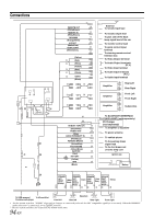
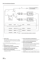
Foot Brake Lead / Parking Brake Lead Connection, Connection Diagram of SPST Switch sold separately - antenna
 |
UPC - 793276100276
View all Alpine INA-W900BT manuals
Add to My Manuals
Save this manual to your list of manuals |
Page 95 highlights
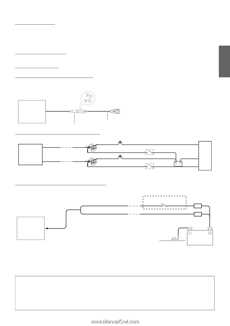
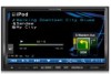
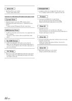
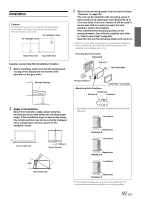
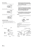
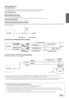
Install the GPS antenna 1. Stick the ground pad at the center of dash board and close to windshield with one inch distance. 2. Attach GPS antenna to the center of ground pad. (the cable side faces the back of vehicle) At the front or back of vehicle roof. Wiring the GPS antenna cable Do not bend or fold the GPS antenna cable. • When installing the INA-W900 to the vehicle, make sure the back of unit and the cable must not be bent. Connect the GPS antenna Securely connect the GPS antenna connector to INA-W900. Connection of USB extension cable (included) Connect the USB extension cable to the USB connector of the unit, and then secure the connection using the lock case supplied with USB extension cable as shown below. INA-W900 USB Connector Cable (Supplied) Foot Brake Lead / Parking Brake Lead Connection INA-W900 FOOT BRAKE (Yellow/Black) Pinch Connector (sold separately) PARKING BRAKE (Yellow/Blue) Pinch Connector (sold separately) Foot brake lamp Foot brake lead Parking brake lamp Parking brake lead Foot brake switch Chassis Battery Parking brake switch Connection Diagram of SPST Switch (sold separately) (If the ACC power supply is not available) INA-W900 IGNITION (Red) BATTERY (Yellow) SPST SW (Optional) FUSE (5A) (Optional) FUSE (20A) (Optional) Battery • If your vehicle has no ACC power supply, add an SPST (Single-Pole, Single-Throw) switch (sold separately) and fuse (sold separately). • The diagram and the fuse amperage shown above are in the case when INA-W900 is used individually. • If the switched power (ignition) lead of the INA-W900 is connected directly to the positive (+) post of the vehicle's battery, the INA-W900 draws some current (several hundred milliamperes) even when its switch is placed in the OFF position and the battery may be discharged. To prevent external noise from entering the audio system. • Locate the unit and route the leads at least 10 cm away from the car harness. • Keep the battery power leads as far away from other leads as possible. • Connect the ground lead securely to a bare metal spot (remove any paint, dirt or grease if necessary) of the car chassis. • If you add an optional noise suppressor, connect it as far away from the unit as possible. Your Alpine dealer carries various noise suppressors, contact them for further information. • Your Alpine dealer knows best about noise prevention measures so consult your dealer for further information. 93-EN
-
 1
1 -
2
-
3
-
4
-
5
-
6
-
7
-
8
-
9
-
10
-
11
-
12
-
13
-
14
-
15
-
16
-
17
-
18
-
19
-
20
-
21
-
22
-
23
-
24
-
25
-
26
-
27
-
28
-
29
-
30
-
31
-
32
-
33
-
34
-
35
-
36
-
37
-
38
-
39
-
40
-
41
-
42
-
43
-
44
-
45
-
46
-
47
-
48
-
49
-
50
-
51
-
52
-
53
-
54
-
55
-
56
-
57
-
58
-
59
-
60
-
61
-
62
-
63
-
64
-
65
-
66
-
67
-
68
-
69
-
70
-
71
-
72
-
73
-
74
-
75
-
76
-
77
-
78
-
79
-
80
-
81
-
82
-
83
-
84
-
85
-
86
-
87
-
88
-
89
-
 90
90 -
 91
91 -
 92
92 -
 93
93 -
 94
94 -
 95
95 -
 96
96 -
 97
97 -
 98
98 -
 99
99 -
 100
100 -
101
 |
 |