Alpine INA-W900BT Owner's Manual (English) - Page 97
Audio Interrupt In Lead Pink/Black, Video Output Connector AUX OUTPUT Yellow - bluetooth update
 |
UPC - 793276100276
View all Alpine INA-W900BT manuals
Add to My Manuals
Save this manual to your list of manuals |
Page 97 highlights
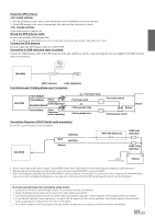
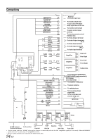
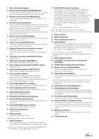
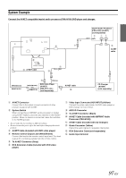
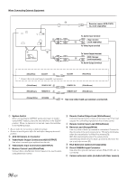
Radio Antenna Receptacle Remote Control Output Lead (White/Brown) Connect this lead to the remote control input lead. This lead outputs the controlling signals from the remote control. Remote Control Input Lead (White/Brown) Connect the external Alpine product to the remote control output lead. Reverse Lead (Orange/White) Use only when a back-up camera is connected. Connect to the plus side of the car's reverse lamp. This lamp illuminates when the transmission is shifted into reverse (R). With this lead properly wired, the video picture automatically switches to the back-up camera whenever the car is put into reverse (R). Monitor Control Lead (White/Pink) Connect this to the Monitor Control Lead of the touch panelcompatible rear monitor. Guide Control Lead (White/Green) Use when an optional External Audio Processor with guide control input terminal is connected. Steering Remote Control Interface Connector To steering remote control interface box. For details about connections, consult your nearest Alpine dealer. Video Input Connector (AUX INPUT) (Yellow) Input the video. Audio Input Connectors (AUX INPUT) RED is right and WHITE is left input the audio. Video Output Connector (AUX OUTPUT) (Yellow) Output the video. Audio Output Connectors (AUX OUTPUT) RED is right and WHITE is left output the audio. Guide Connector (Black) Output the audio signal of navigation interruption. When connecting an IMPRINT Audio processor (PXA-H100), connect this lead to the Guide Input terminal with an optional RCA Extension cable. Rear Output/Input RCA Connectors It can be used as Rear Output or Input RCA Connectors. Front Output/Input RCA Connectors It can be used as Front Output or Input RCA Connectors. Subwoofer RCA Connectors RED is right and WHITE is left. RCA Extension Cable (sold separately) Direct CAMERA Input Connector Use when the optional rearview camera HCE-C107D, etc. is connected. iPod AUDIO/VIDEO Input Connector Connect this to the AV extension cable. GPS Antenna Receptacle To GPS Antenna. MSN Connector To MSN Direct Box HCE-900m. • MSN Direct feature is ready on future update. Ai-NET Connector Connect this to the output or input connector of another device (CD Changer, Equalizer, etc.) equipped with Ai-NET. • Be sure to set "Setting the Connected Head Unit (MODEL SETUP)" to "DVD CHG", when the DHA-S690 is connected. BLUETOOTH interface Connector Connect this to an optional BLUETOOTH INTERFACE (KCE-400BT). To use a hands-free mobile phone, an optional BLUETOOTH INTERFACE (KCE-400BT) connection is required. For details on connection, refer to the Owner's Manual of the BLUETOOTH INTERFACE (KCE-400BT). You can also connect this to an external device (such as a portable player) by using conversion cable (KCE-237B) for building up the AUX IN (sold separately). • Refer to "Setting the AUX+ Mode" (page 55). AUX+ ON: When the external device is connected. AUX+ OFF: When set to OFF, AUX+ source cannot be selected. USB Connector AUX I/O Connector RCA Output/Input Connector System Switch When connecting an IMPRINT Audio Processor (PXA-H100) or divider using Ai-NET feature, place the two switches in the EQ/DIV position. When no device is connected, leave the switches in the NORM position. • Do not make the two switches to different settings. • Be sure to turn the power off to the unit before changing the switch position. Power Supply Connector KCE-400BT Connection Cable (Included with KCE-400BT) Ai-NET Cable (Included with CD Changer) Remote Turn-On Lead (Blue/White) Connect this lead to the remote turn-on lead of your amplifier or signal processor. Power Antenna Lead (Blue) Connect this lead to the +B terminal of your power antenna, if applicable. • This lead should be used only for controlling the vehicle's power antenna. Do not use this lead to turn on an amplifier or a signal processor, etc. Audio Interrupt In Lead (Pink/Black) Parking Brake Lead (Yellow/Blue) Connect this lead to the power supply side of the parking brake switch to transmit the parking brake status signals to the INA-W900. Foot Brake Lead (Yellow/Black) Connect to the vehicle's foot brake lead or brake lamp lead. Switched Power Lead (Ignition) (Red) Connect this lead to an open terminal on the vehicle's fuse box or another unused power source which provides (+) 12V only when the ignition is turned on or in the accessory position. Battery Lead (Yellow) Connect this lead to the positive (+) post of the vehicle's battery. Fuse Holder (10A) 95-EN
-
 1
1 -
2
-
3
-
4
-
5
-
6
-
7
-
8
-
9
-
10
-
11
-
12
-
13
-
14
-
15
-
16
-
17
-
18
-
19
-
20
-
21
-
22
-
23
-
24
-
25
-
26
-
27
-
28
-
29
-
30
-
31
-
32
-
33
-
34
-
35
-
36
-
37
-
38
-
39
-
40
-
41
-
42
-
43
-
44
-
45
-
46
-
47
-
48
-
49
-
50
-
51
-
52
-
53
-
54
-
55
-
56
-
57
-
58
-
59
-
60
-
61
-
62
-
63
-
64
-
65
-
66
-
67
-
68
-
69
-
70
-
71
-
72
-
73
-
74
-
75
-
76
-
77
-
78
-
79
-
80
-
81
-
82
-
83
-
84
-
85
-
86
-
87
-
88
-
89
-
90
-
91
-
 92
92 -
 93
93 -
 94
94 -
 95
95 -
 96
96 -
 97
97 -
 98
98 -
 99
99 -
 100
100 -
 101
101
 |
 |