Alpine IVA W205 Owners Manual - Page 73
Installation
 |
UPC - 093276200588
View all Alpine IVA W205 manuals
Add to My Manuals
Save this manual to your list of manuals |
Page 73 highlights
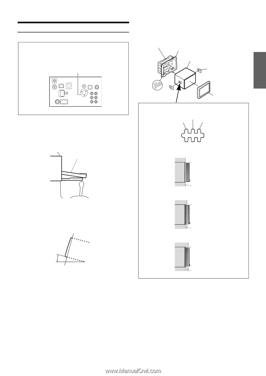
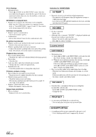
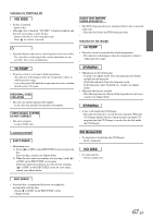
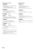
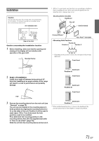
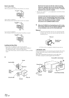
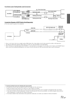
Installation Caution Do not block the unit's fan or heat sink, thus preventing air circulation. If blocked, heat will accumulate inside the unit and may cause a fire. Air ventilation hole • If B or C is used, make sure that there is a enough space depthwise before installing the unit. If the unit is forcibly pushed into the mounting sleeve, damage may occur. Mounting Sleeve (Included) Dashboard this unit Seal (Included) Rear of the Unit Caution concerning the installation location 1 Before installing, make sure that the opening and closing of the display will not interfere with operation of the gear shift. Movable Display Pressure Plates*1 Face Plate*2 (Included) Position B Position A Position C • Depending on the position chosen, the front panel will protrude differently. Front Panel 2 Angle of installation Install at an angle of between horizontal and 30°. Note that installing at an angle outside of this range will result in a loss of performance and possibly damage. Dashboard Position A Front Panel Dashboard Position B 0-30° Front Panel 3 Remove the mounting sleeve from the main unit (see "Removal" on page 72). The unit can be installed in the mounting sleeve in three positions by aligning its mounting holes (A to C) on the sides of the unit. Position A will be used in most cases. If B or C are to be used, the hole positions need to be modified. First, determine the mounting position in the mounting sleeve, then affix the supplied seal (refer to "How to use a Seal" (page 72)). Slide the unit into the mounting sleeve and secure it. Dashboard Position C *1 If the installed mounting sleeve is loose in the dashboard, the pressure plates may be bent slightly to remedy the problem. 71-EN
-
 1
1 -
2
-
3
-
4
-
5
-
6
-
7
-
8
-
9
-
10
-
11
-
12
-
13
-
14
-
15
-
16
-
17
-
18
-
19
-
20
-
21
-
22
-
23
-
24
-
25
-
26
-
27
-
28
-
29
-
30
-
31
-
32
-
33
-
34
-
35
-
36
-
37
-
38
-
39
-
40
-
41
-
42
-
43
-
44
-
45
-
46
-
47
-
48
-
49
-
50
-
51
-
52
-
53
-
54
-
55
-
56
-
57
-
58
-
59
-
60
-
61
-
62
-
63
-
64
-
65
-
66
-
67
-
 68
68 -
 69
69 -
 70
70 -
 71
71 -
 72
72 -
 73
73 -
 74
74 -
 75
75 -
 76
76 -
 77
77 -
 78
78 -
79
-
80
-
81
-
82
-
83
-
84
-
85
-
86
-
87
-
88
-
89
-
90
-
91
-
92
-
93
-
94
-
95
-
96
-
97
-
98
-
99
-
100
-
101
-
102
-
103
-
104
-
105
-
106
-
107
-
108
-
109
-
110
-
111
-
112
-
113
-
114
-
115
-
116
-
117
-
118
-
119
-
120
-
121
-
122
-
123
-
124
-
125
-
126
-
127
-
128
-
129
-
130
-
131
-
132
-
133
-
134
-
135
-
136
-
137
-
138
-
139
-
140
-
141
-
142
-
143
-
144
-
145
-
146
-
147
-
148
-
149
-
150
-
151
-
152
-
153
-
154
-
155
-
156
-
157
-
158
-
159
-
160
-
161
-
162
-
163
-
164
-
165
-
166
-
167
-
168
-
169
-
170
-
171
-
172
-
173
-
174
-
175
-
176
-
177
-
178
-
179
-
180
-
181
-
182
-
183
-
184
-
185
-
186
-
187
-
188
-
189
-
190
-
191
-
192
-
193
-
194
-
195
-
196
-
197
-
198
-
199
-
200
-
201
-
202
-
203
-
204
-
205
-
206
-
207
-
208
-
209
-
210
-
211
-
212
-
213
-
214
-
215
-
216
-
217
-
218
-
219
-
220
-
221
-
222
-
223
-
224
-
225
-
226
-
227
-
228
-
229
-
230
-
231
-
232
-
233
-
234
-
235
-
236
-
237
-
238
 |
 |