Alpine IVA W205 Owners Manual - Page 77
Right Front - Speaker Output Lead Gray/Black - camera
 |
UPC - 093276200588
View all Alpine IVA W205 manuals
Add to My Manuals
Save this manual to your list of manuals |
Page 77 highlights
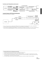
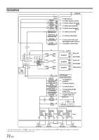
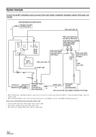
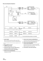
Radio Antenna Receptacle MIC Input Connector To Microphone (sold separately). Video Input Connector (AUX INPUT) (Yellow) Input the video. Audio Input Connectors (AUX INPUT) RED is right and WHITE is left input the audio. Video Output Connector (AUX OUTPUT) (Yellow) Output the video. Audio Output Connectors (AUX OUTPUT) RED is right and WHITE is left output the audio. Remote Control Output Lead (White/Brown) Connect this lead to the remote control input lead. This lead outputs the controlling signals from the remote control. Remote Control Input Lead (White/Brown) Connect the external Alpine product to the remote control output lead. Reverse Lead (Orange/White) Use only when a back-up camera is connected. Connect to the plus side of the car's reverse lamp that lights when the transmission is shifted into reverse (R). Switches the video picture to the back-up camera. This is linked with putting the car into reverse (R). Monitor Control Lead (White/Pink) Connect this to the Monitor Control Lead of the touch panelcompatible rear monitor. RCA Extension Cable (sold separately) Remote IN/OUT Connector FULL SPEED™ Connection Cable (KCE-422i) (sold separately) GPS Antenna Receptacle To GPS Antenna (sold separately). Steering Remote Control Interface Connector To steering remote control interface box. For details about connections, consult your nearest Alpine dealer. iPod Direct Connector iPod control signals. Connect this to an iPod or an optional Bluetooth Box, using the FULL SPEED™ Connection Cable (KCE-422i) (sold separately). To use a hands-free mobile phone, an optional Bluetooth Box connection is required. For details on connection, refer to the Owner's Manual of the Bluetooth Box. CAMERA Input Terminal Use when connecting a back-up camera. RGB Input Terminal Connect this to the RGB output terminal of the Navigation System. TMC Antenna Receptacle To TMC Antenna (sold separately). Digital Output Terminal (Optical) Use when combining fiber optic digital input compatible products. Ai-NET Connector Connect this to the output or input connector of another device (CD Changer, Equalizer, HD Radio™ TUNER MODULE, etc.) equipped with Ai-NET. • You can input TV/video sound by connecting an optional Ai-NET/RCA Interface cable (KCA-121B) to this component. Rear Output RCA Connectors RED is right and WHITE is left. Front Output RCA Connectors RED is right and WHITE is left. Subwoofer RCA Connectors RED is right and WHITE is left. System Switch When connecting an equalizer or divider using Ai-NET feature, place this switch in the EQ/DIV position. When no device is connected, leave the switch in the NORM position. • Be sure to turn the power off to the unit before changing the switch position. Power Supply Connector Ai-NET Cable (Included with CD Changer) Remote Turn-On Lead (Blue/White) Connect this lead to the remote turn-on lead of your amplifier or signal processor. Power Antenna Lead (Blue) Connect this lead to the +B terminal of your power antenna, if applicable. • This lead should be used only for controlling the vehicle's power antenna. Do not use this lead to turn on an amplifier or a signal processor, etc. Audio Interrupt In Lead (Pink/Black) Parking Brake Lead (Yellow/Blue) Connect this lead to the power supply side of the parking brake switch to transmit the parking brake status signals to the IVA-W205. Foot Brake Lead (Yellow/Black) Connect to the vehicle's foot brake lead or brake lamp lead. Switched Power Lead (Ignition) (Red) Connect this lead to an open terminal on the vehicle's fuse box or another unused power source which provides (+) 12V only when the ignition is turned on or in the accessory position. Battery Lead (Yellow) Connect this lead to the positive (+) post of the vehicle's battery. Fuse Holder (10A) Ground Lead (Black) Connect this lead to a good chassis ground on the vehicle. Make sure the connection is made to bare metal and is securely fastened using the sheet metal screw provided. Right Front (+) Speaker Output Lead (Gray) Right Front (-) Speaker Output Lead (Gray/Black) Right Rear (-) Speaker Output Lead (Violet/Black) Right Rear (+) Speaker Output Lead (Violet) Left Rear (+) Speaker Output Lead (Green) Left Rear (-) Speaker Output Lead (Green/Black) Left Front (-) Speaker Output Lead (White/Black) Left Front (+) Speaker Output Lead (White) 75-EN
-
 1
1 -
2
-
3
-
4
-
5
-
6
-
7
-
8
-
9
-
10
-
11
-
12
-
13
-
14
-
15
-
16
-
17
-
18
-
19
-
20
-
21
-
22
-
23
-
24
-
25
-
26
-
27
-
28
-
29
-
30
-
31
-
32
-
33
-
34
-
35
-
36
-
37
-
38
-
39
-
40
-
41
-
42
-
43
-
44
-
45
-
46
-
47
-
48
-
49
-
50
-
51
-
52
-
53
-
54
-
55
-
56
-
57
-
58
-
59
-
60
-
61
-
62
-
63
-
64
-
65
-
66
-
67
-
68
-
69
-
70
-
71
-
 72
72 -
 73
73 -
 74
74 -
 75
75 -
 76
76 -
 77
77 -
 78
78 -
 79
79 -
 80
80 -
 81
81 -
 82
82 -
83
-
84
-
85
-
86
-
87
-
88
-
89
-
90
-
91
-
92
-
93
-
94
-
95
-
96
-
97
-
98
-
99
-
100
-
101
-
102
-
103
-
104
-
105
-
106
-
107
-
108
-
109
-
110
-
111
-
112
-
113
-
114
-
115
-
116
-
117
-
118
-
119
-
120
-
121
-
122
-
123
-
124
-
125
-
126
-
127
-
128
-
129
-
130
-
131
-
132
-
133
-
134
-
135
-
136
-
137
-
138
-
139
-
140
-
141
-
142
-
143
-
144
-
145
-
146
-
147
-
148
-
149
-
150
-
151
-
152
-
153
-
154
-
155
-
156
-
157
-
158
-
159
-
160
-
161
-
162
-
163
-
164
-
165
-
166
-
167
-
168
-
169
-
170
-
171
-
172
-
173
-
174
-
175
-
176
-
177
-
178
-
179
-
180
-
181
-
182
-
183
-
184
-
185
-
186
-
187
-
188
-
189
-
190
-
191
-
192
-
193
-
194
-
195
-
196
-
197
-
198
-
199
-
200
-
201
-
202
-
203
-
204
-
205
-
206
-
207
-
208
-
209
-
210
-
211
-
212
-
213
-
214
-
215
-
216
-
217
-
218
-
219
-
220
-
221
-
222
-
223
-
224
-
225
-
226
-
227
-
228
-
229
-
230
-
231
-
232
-
233
-
234
-
235
-
236
-
237
-
238
 |
 |