Alpine M450 User Manual
Alpine M450 - V-Power MRP Amplifier Manual
 |
UPC - 793276300782
View all Alpine M450 manuals
Add to My Manuals
Save this manual to your list of manuals |
Alpine M450 manual content summary:
- Alpine M450 | User Manual - Page 1
MRP-M650/MRP-M450 MONO POWER AMPLIFIER • OWNER'S MANUAL Please read this manual to maximize your enjoyment of the outstanding performance and feature capabilities of the equipment, then retain the manual DIAGRAMS 10 SPECIFICATIONS 12 TABLE DES MATIERES AVERTISSEMENT 2 ATTENTION 3 INSTALLATION - Alpine M450 | User Manual - Page 2
: Please read this OWNER'S MANUAL thoroughly to familiarize yourself with each control and function. We at ALPINE hope that your new MRP-M650/MRP-M450 will give you many years of listening enjoyment. In case of problems when installing your MRP-M650/ MRP-M450, please contact your authorized - Alpine M450 | User Manual - Page 3
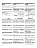
HALT USE IMMEDIATELY IF A PROBLEM APPEARS. Failure to do so may cause personal injury or damage to the product. Return it to your authorized Alpine dealer or the nearest Alpine Service Center for repairing. HAVE THE WIRING AND INSTALLATION DONE BY EXPERTS. The wiring and installation of this unit - Alpine M450 | User Manual - Page 4
installation locations, please contact your authorized Alpine dealer. 1. Using the amplifier as a template, mark the four screw locations. 2. Make sure there are no objects behind the surface that may become damaged during drilling. 3. Drill the screw holes. 4. Position the MRP-M650/MRP-M450 - Alpine M450 | User Manual - Page 5
English ATTACHING THE TERMINAL COVERS • Attach the terminal covers (supplied) after connec- tions and confirmation of correct operation. • Attaching the terminal covers will improve the ap- pearance of the unit. Français MONTAGE DES CACHE-BORNES • Montez les cache-bornes (fournis) une fois que les - Alpine M450 | User Manual - Page 6
leads on your head unit using RCA extension cables (sold separately). Be sure to observe correct channel connections; Left to Left and Right to Right. 2 Speaker Output Terminals The MRP-M650/MRP-M450 has one set of speaker outputs. Be sure to observe correct speaker output connections and phasing - Alpine M450 | User Manual - Page 7
outputs. When not using the RCA Line Input connectors, you should connect these wires to the speaker output leads of your head unit. The MRP-M650/MRP-M450 accepts input from high power or standard power head units. 8 Left Speaker (White (+)) 9 Left Speaker (White/Black (-)) Ä Right Speaker (Gray - Alpine M450 | User Manual - Page 8
) the MRP-M650/MRP-M450. Therefore, the switch should be mounted so it is accessible to the driver. Make sure the switch is turned off when the vehicle is not running. Otherwise, the amplifier will remain on and drain the battery. 1 Blue/White 2 Power Antenna 3 Remote Turn-On Lead 4 To other Alpine - Alpine M450 | User Manual - Page 9
0.5V MIN MAX GAIN +6dB 100 75 140 55 170 0dB +12dB 50 200 (Hz) BASS EQ LP FILTER CHANNEL - 1/2 12 13 14 Fig. 5 15 SWITCH SETTINGS Ç Input Gain Adjustment Control Set the MRP-M650/MRP-M450 input gain to the minimum (4V) position. Using a dynamic CD as a source, increase the head - Alpine M450 | User Manual - Page 10
17 (R) (L) 18 Fig. 6 Important Tips on Bridging an Amplifier/Conseils importants lors de la mise en pont d'un amplificateur/Consejos importantes cuando conecte en puente un amplificador NOTE: The following problem may occur if the amp is not properly connected. • Low output when only one input - Alpine M450 | User Manual - Page 11
INPUT (R) NOM 0.5V MIN MAX GAIN +6dB 100 75 140 55 170 0dB +12dB 50 200 (Hz) BASS EQ LP FILTER CHANNEL - 1/2 (Right side/Côté droit/ Lado derecho) 7 # 8 CH 1 + 11 CH 2 - CH 1 la Fig. 8. ä[English] Other AMP ä[Français] Autre amplificateur ä[Español] Otro amplificador 11 - Alpine M450 | User Manual - Page 12
English SPECIFICATIONS RMS Continuous Power (at 14.4V, 20 - 200Hz) • Per channel into 4 ohms (1%THD): MRP-M650 400Wx1 MRP-M450 220Wx1 • Per channel into 2 ohms (1%THD): MRP-M650 600Wx1 MRP-M450 400Wx1 S/N Ratio • IHF A Weighted,Reference: rated power into 4ohms 90 dBA • IHF A Weighted,CEA2006, - Alpine M450 | User Manual - Page 13
English SERVICE CARE Français SOINS PRATIQUES Español CUIDADOS PRÁCTICOS IMPORTANT NOTICE This Amplifier has been type tested and radio frequency energy, and it must be installed and used properly in accordance with the manufacturer's instructions. AVIS IMPORTANT Cet amplificateur a été testé - Alpine M450 | User Manual - Page 14
- Alpine M450 | User Manual - Page 15
par le non-respect des instructions indiquées dans le installation autorisé ait installé le système audio pour l'auto dans votre véhicule et qu'il ait ensuite apposé son cachet sur la garantie. [NUMÉROS D'APPEL DU SERVICE À LA CLIENTÈLE Si vous avez besoin de nos services, veuillez appeler Alpine - Alpine M450 | User Manual - Page 16
the speaker (amplifier level is follow instructions contained in the Owner's manual. installation by the installation center. [HOW TO CONTACT CUSTOMER SERVICE: Should the product require service, please call the following number for your nearest Authorized Alpine Service Center. CAR AUDIO 1-800-ALPINE
-
 1
1 -
 2
2 -
 3
3 -
 4
4 -
 5
5 -
 6
6 -
 7
7 -
8
-
9
-
10
-
11
-
12
-
13
-
14
-
15
-
16
 |
 |

R
• OWNER'S MANUAL
Please read this manual to maximize your enjoyment of the outstanding
performance and feature capabilities of the equipment, then retain the
manual for future reference.
• MODE D'EMPLOI
Veuillez lire ce mode d'emploi pour tirer pleinement profit des
excellentes performances et fonctions de cet appareil, et conservez-le
pour toute référence future.
• MANUAL DE OPERACIÓN
Lea este manual, por favor, para disfrutar al máximo de las
excepcionales prestaciones y posibilidades funcionales que ofrece el
equipo, luego guarde el manual para usarlo como referencia en el futuro.
MRP-M650/MRP-M450
MONO POWER AMPLIFIER
CONTENTS
WARNING
...............................................................
2
CAUTION
................................................................
3
INSTALLATION
.......................................................
4
ATTACHING THE TERMINAL COVERS
....................
5
CONNECTIONS
.......................................................
6
CONNECTIONS CHECK LIST
...................................
8
SWITCH SETTINGS
................................................
9
SYSTEM DIAGRAMS
............................................
10
SPECIFICATIONS
..................................................
12
ACCESSORIES
•
Self-Tapping Screw (M4)
....................................
4
•
Terminal Cover
...........................................
1 SET
•
Screw (M3)
........................................................
4
•
Speaker Input Connector
....................................
1
TABLE DES MATIERES
AVERTISSEMENT
......................................................
2
ATTENTION
................................................................
3
INSTALLATION
..........................................................
4
MONTAGE DES CACHE-BORNES
...............................
5
CONNEXIONS
............................................................
6
LISTE DE VERIFICATION DES CONNEXIONS
.............
8
REGLAGES DE COMMUTATEUR
................................
9
DIAGRAMMES DU SYSTEME
..................................
10
SPECIFICATIONS
.....................................................
12
ACCESSOIRES
•
Vis autotaraudeuse (M4)
.......................................
4
•
Cache-bornes
................................................
1 JEU
•
Vis (M3)
................................................................
4
•
Connecteur d’entrée de haut-parleur
..........................
1
ÍNDICE
ADVERTENCIA
........................................................
2
PRUDENCIA
...........................................................
3
INSTALACIÓN
.........................................................
4
ACOPLAR LAS CUBIERTAS DEL TERMINAL
..........
5
CONEXIONES
.........................................................
6
LISTA DE VERIFICACIÓN DE CONEXIONES
............
8
AJUSTES DEL INTERRUPTOR
................................
9
DIAGRAMAS DEL SISTEMA
.................................
10
ESPECIFICACIONES
.............................................
12
ACCESORIOS
•
Tornillo autorroscante (M4)
................................
4
•
Cubierta del terminal
.............................
1 JUEGO
•
Tornillo (M3)
......................................................
4
•
Conector de entrada del altavoz
.........................
1
Espa
ñ
ol
Fran
ç
ais
English
ALPINE ELECTRONICS MARKETING, INC.
1-1-8 Nishi Gotanda,
Shinagawa-ku,
Tokyo 141-0031, Japan
Phone 03-5496-8231
ALPINE ELECTRONICS OF AMERICA, INC.
19145 Gramercy Place, Torrance,
California 90501, U.S.A.
Phone 1-800-ALPINE-1 (1-800-257-4631)
ALPINE ELECTRONICS OF CANADA, INC.
777 Supertest Road, Toronto,
Ontario M3J 2M9, Canada
Phone 1-800-ALPINE-1 (1-800-257-4631)
ALPINE ELECTRONICS OF AUSTRALIA PTY. LTD.
161-165 Princes Highway, Hallam
Victoria 3803, Australia
Phone 03-8787-1200
ALPINE ELECTRONICS GmbH
Frankfurter Ring 117, 80807 München, Germany
Phone 089-32 42 640
ALPINE ELECTRONICS OF U.K. LTD.
Alpine House
Fletchamstead Highway, Coventry CV4 9TW, U.K.
Phone 0870-33 33 763
ALPINE ELECTRONICS FRANCE S.A.R.L.
(RCS PONTOISE B 338 101 280)
98, Rue de la Belle Etoile, Z.I. Paris Nord II,
B.P. 50016, 95945 Roissy Charles de Gaulle
Cedex, France
Phone 01-48638989
ALPINE ITALIA S.p.A.
Viale C. Colombo 8, 20090 Trezzano
Sul Naviglio (MI), Italy
Phone 02-484781
ALPINE ELECTRONICS DE ESPAÑA, S.A.
Portal de Gamarra 36, Pabellón, 32
01013 Vitoria (Alava) - APDO 133, Spain
Phone 945-283588
ALPINE ELECTRONICS (BENELUX) GmbH
Leuvensesteenweg 510-B6,
1930 Zaventem, Belgium
Phone 02-725-13 15
Kukje Printing Co., Ltd
127-2 Gamjeon-dong
Sasang-gu
Busan Korea
Designed by ALPINE Japan
Printed in Korea (S)
68-05946Z13-A