Alpine MRX-V70 Owner's Manual (english, French, Espanol)
Alpine MRX-V70 Manual
 |
View all Alpine MRX-V70 manuals
Add to My Manuals
Save this manual to your list of manuals |
Alpine MRX-V70 manual content summary:
- Alpine MRX-V70 | Owner's Manual (english, French, Espanol) - Page 1
MRX-V70 4 CHANNEL + MONO POWER AMPLIFIER MRX-F35 4 CHANNEL POWER AMPLIFIER • OWNER'S MANUAL Please read this manual 11 SYSTEM DIAGRAMS 13 SPECIFICATIONS 19 SERVICE CARE 20 ACCESSORIES • Self-Tapping de haut-parleur 1 • Clé hexagonale 1 ALPINE ELECTRONICS OF AUSTRALIA PTY. LTD. 161-165 Princes - Alpine MRX-V70 | Owner's Manual (english, French, Espanol) - Page 2
Le non-respect de ces instructions peut entraîner des blessures ou des dommages matériels. Introducción: A fin de familiarizarse con los controles y funciones de la unidad, lea detenidamente este MANUAL DE OPERACIÓN. Nosotros en ALPINE esperamos que su nuevo MRX-V70/MRX-F35 le brinde muchos años de - Alpine MRX-V70 | Owner's Manual (english, French, Espanol) - Page 3
cut away cable insulation to supply power to other equipment. Doing so conforme a lo descrito en el manual para evitar obstáculos durante la PROBLEM APPEARS. Failure to do so may cause personal injury or damage to the product. Return it to your authorized Alpine dealer or the nearest Alpine Service - Alpine MRX-V70 | Owner's Manual (english, French, Espanol) - Page 4
ais Español INSTALLATION Due to the high power output of the MRX-V70/MRX-F35, considerable heat is produced when the amplifier érentes positions d'installation, contacter un concessionnaire Alpine. Debido a la salida de alta potencia del MRX-V70/MRX-F35, se produce un calor considerable cuando el - Alpine MRX-V70 | Owner's Manual (english, French, Espanol) - Page 5
English Français Español ATTACHING THE TERMINAL COVERS Attach the terminal covers (supplied) after connections and confirmation of correct operation. Attaching the terminal covers will improve the appearance of the unit. How to attach the terminal covers: Attach the left and right terminal covers - Alpine MRX-V70 | Owner's Manual (english, French, Espanol) - Page 6
30 30 (Left Side/Côté gauche/ Lado izquierdo) a b d e f MRX-F35 c q g h (Right Side/ i Côté droit/ Lado derecho) j power off to all audio components. Connect the battery lead from the amp Alpine dealer carries various noise suppressors, contact them for further information. • Your Alpine - Alpine MRX-V70 | Owner's Manual (english, French, Espanol) - Page 7
del vehículo. In the bridged mode, connect the left positive MRX-V70 30A x2 • MRX-F35 25A x2 UTILICE EL AMPERAJE CORRECTO CUANDO CAMBIE FUSIBLES. De lo contrario, puede producirse un incendio o una descarga eléctrica. c Power requirement. MRX-V70 60 amp fuse, 4AWG/21mm2 MRX-F35 50 amp fuse, - Alpine MRX-V70 | Owner's Manual (english, French, Espanol) - Page 8
not using the RCA Line Input connectors, you should connect these wires to the speaker output leads of your head unit. The MRX-V70/MRX-F35 accepts input from high power or standard power head units. NOTES: • If connecting the Speaker Input Leads and RCA Inputs at the same time, be sure to connect to - Alpine MRX-V70 | Owner's Manual (english, French, Espanol) - Page 9
power cable near the battery positive post. 1. Check the wire size. NOTES: • Required Wire Size (Battery Lead, Ground Lead): MRX-V70 4AWG/21mm2 MRX-F35 cessaire): MRX-V70 2AWG (33mm2) ou 1/0AWG (53mm2) MRX-F35 4AWG (21mm2) ou 2AWG (33mm2) Veillez à installer un fusible en ligne de l'ampérage - Alpine MRX-V70 | Owner's Manual (english, French, Espanol) - Page 10
's power antenna. If any of the above conditions exist, the remote turn-on lead of your MRX-V70/MRX-F35 must be connected to a switched power source y agotará la batería. A Blue/White B Power Antenna C Remote Turn-On Lead D To other Alpine components' Remote Turn-On Leads E SPST Switch (optional - Alpine MRX-V70 | Owner's Manual (english, French, Espanol) - Page 11
-V70 English s tu v tu v Français Español MRX-F35 w tx y z t 1 ut 1 uz 2 Fig. 7 SWITCH SETTINGS NOTE: Before switching each Selector Switch, turn off the power and insert a small screwdriver, etc., perpendicularly to the Switch. RÉGLAGES DE COMMUTATEUR REMARQUE: Avant de procéder au réglage - Alpine MRX-V70 | Owner's Manual (english, French, Espanol) - Page 12
dB para configurar sus necesidades de graves. 1 Crossover Mode Selector Switch (MRX-F35 only) a) Set to the "OFF" position when the amplifier will be (a razón de 12 dB por octava). 2 Power Indicator Lights up when power is on. Is off when power is off. 12 2 Indicateur d'alimentation Allumé lors - Alpine MRX-V70 | Owner's Manual (english, French, Espanol) - Page 13
Switch/Commutateur sélecteur du canal d'entrée/Interruptor de selector de canal de entrada · · · 3/4 · · · SUB W. 8 L R 9 L R MRX-F35 (Left side/ Côté gauche/ Lado izquierdo) 0 d f 8 L R (Right side/ Côté droit/ Lado derecho) 4 44 (L) (R) (R) (L) (R) (L) e 5 6 7 ; 30 30 25 - Alpine MRX-V70 | Owner's Manual (english, French, Espanol) - Page 14
• Bridged Connections/Connexions pontées/Conexiones puenteadas MRX-V70 Input Channel Selector Switch/Commutateur sélecteur du canal d'entrée/Interruptor de selector de canal de entrada · · · 3/4 · · · 1+2+3+4 8 L R 30 30 MRX-F35 (Left side/ Côté gauche/ Lado izquierdo) 0 d f e (Right - Alpine MRX-V70 | Owner's Manual (english, French, Espanol) - Page 15
one channel input is used. The Y-adapter is not required if a stereo/mono pair line output is used to drive both inputs of the bridged amp. REMARQUE : Le système présente une faible puissance en cas d'utilisation d'un seul canal d'entrée. L'adaptateur Y n'est pas requis en cas d'utilisation d'une - Alpine MRX-V70 | Owner's Manual (english, French, Espanol) - Page 16
• System example of 2-Channel input/Exemple de système muni d'une entrée à 2 canaux/Ejemplo de sistema de entrada de 2 canales MRX-V70 Input Channel Selector Switch/Commutateur sélecteur du canal d'entrée/Interruptor de selector de canal de entrada • This switch setting also applies for 2-channel - Alpine MRX-V70 | Owner's Manual (english, French, Espanol) - Page 17
9 L R d 1e f 30 30 25 25 (Left side/ Côté gauche/ Lado izquierdo) MRX-F35 8 L R (Right side/ Côté droit/ 2 g Lado derecho) 0 i jk p no case, connect the Remote Turn-On Lead to an incoming power supply cord (accessory power) in the ACC position. ★2 If connecting the Speaker Input - Alpine MRX-V70 | Owner's Manual (english, French, Espanol) - Page 18
RCA/Ejemplo de sistema con conexiones de nivel de altavoz y de entrada RCA MRX-V70 Input Channel Selector Switch/Commutateur sélecteur du canal d'entrée/Interruptor de selector connect the Remote Turn-On Lead to an incoming power supply cord (accessory power) in the ACC position. ★2 If connecting - Alpine MRX-V70 | Owner's Manual (english, French, Espanol) - Page 19
English Français Español SPECIFICATIONS MRX-V70 MRX-F35 CH-1/2/3/4 SUB W. Per Channel Ref: 4Ω, 14.4V at - Alpine MRX-V70 | Owner's Manual (english, French, Espanol) - Page 20
SERVICE CARE ♦ IMPORTANT NOTICE This Amplifier has been type tested and found to frequency energy, and it must be installed and used properly in accordance with the manufacturer's instructions. SERIAL NUMBER: INSTALLATION DATE: INSTALLATION TECHNICIAN: PLACE OF PURCHASE: ♦ IMPORTANT Please record
-
 1
1 -
 2
2 -
 3
3 -
 4
4 -
 5
5 -
 6
6 -
 7
7 -
8
-
9
-
10
-
11
-
12
-
13
-
14
-
15
-
16
-
17
-
18
-
19
-
20
 |
 |

OWNER’S MANUAL
Please read this manual to maximize your enjoyment of the outstanding performance and feature
capabilities of the equipment, then retain the manual for future reference.
MODE D’EMPLOI
Veuillez lire ce mode d’emploi pour tirer pleinement profit des excellentes performances et
fonctions de cet appareil, et conservez-le pour toute référence future.
MANUAL DE OPERACIÓN
Lea este manual, por favor, para disfrutar al máximo de las excepcionales prestaciones y
posibilidades funcionales que ofrece el equipo, luego guarde el manual para usarlo como referencia
en el futuro.
•
•
•
FOR CAR USE ONLY/POUR APPLICATION AUTOMOBILE/PARA USO EN AUTOMÓVILES
MRX-V70
4 CHANNEL + MONO POWER AMPLIFIER
MRX-F35
4 CHANNEL POWER AMPLIFIER
English
Français
Español
CONTENTS
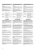
WARNING
.................................................................................
2
CAUTION
...................................................................................
3
INSTALLATION
..........................................................................
4
ATTACHING THE TERMINAL COVERS
...........................................
5
CONNECTIONS
..........................................................................
6
CONNECTION CHECK LIST
........................................................
10
SWITCH SETTINGS
...................................................................
11
SYSTEM DIAGRAMS
................................................................
13
SPECIFICATIONS
......................................................................
19
SERVICE CARE
.........................................................................
20
TABLE DES MATIÈRES
AVERTISSEMENT
.......................................................................
2
ATTENTION
...............................................................................
3
INSTALLATION
..........................................................................
4
FIXATION DES CACHE-BORNES
..................................................
5
CONNEXIONS
............................................................................
6
LISTE DE VÉRIFICATION DES CONNEXIONS
...............................
10
RÉGLAGES DE COMMUTATEUR
................................................
11
DIAGRAMMES DU SYSTÈME
....................................................
13
SPÉCIFICATIONS
......................................................................
19
SOINS PRATIQUES
...................................................................
20
ÍNDICE
ADVERTENCIA
...........................................................................
2
PRUDENCIA
..............................................................................
3
INSTALACIÓN
............................................................................
4
FIJACIÓN DE LAS TAPAS DEL TERMINAL
.....................................
5
CONEXIONES
.............................................................................
6
LISTA DE COMPROBACIÓN DE CONEXIONES
.............................
10
AJUSTES DEL INTERRUPTOR
....................................................
11
DIAGRAMAS DEL SISTEMA
......................................................
13
ESPECIFICACIONES
..................................................................
19
CUIDADOS PRÁCTICOS
............................................................
20
ACCESSORIES
Self-Tapping Screw (M4 × 20)
..............................................
4
Terminal Cover
................................................................
1 SET
Screw (M3 × 10)
..................................................................
4
Speaker Input Connector
......................................................
1
Hexagon Wrench
..................................................................
1
•
•
•
•
•
ACCESSOIRES
Vis autotaraudeuse (M4 × 20)
..............................................
4
Cache-bornes
.................................................................
1 JEU
Vis (M3 × 10)
.......................................................................
4
Connecteur d’entrée de haut-parleur
....................................
1
Clé hexagonale
.....................................................................
1
•
•
•
•
•
ACCESORIOS
Tornillo autorroscante (M4 × 20)
.........................................
4
Tapa del terminal
.......................................................
1 JUEGO
Tornillo (M3 × 10)
................................................................
4
Conector de entrada del altavoz
...........................................
1
Llave hexagonal
...................................................................
1
•
•
•
•
•
ALPINE ELECTRONICS MARKETING, INC.
1-1-8 Nishi Gotanda,
Shinagawa-ku,
Tokyo 141-0031, Japan
Phone
03-5496-8231
ALPINE ELECTRONICS OF AMERICA, INC.
19145 Gramercy Place, Torrance,
California 90501, U.S.A.
Phone 1-800-ALPINE-1 (1-800-257-4631)
ALPINE ELECTRONICS OF CANADA, INC.
777 Supertest Road, Toronto,
Ontario M3J 2M9, Canada
Phone 1-800-ALPINE-1 (1-800-257-4631)
ALPINE ELECTRONICS OF AUSTRALIA PTY. LTD.
161-165 Princes Highway, Hallam
Victoria 3803, Australia
Phone 03-8787-1200
ALPINE ELECTRONICS GmbH
Wilhelm-Wagenfeld-Str. 1-3,
80807 München, Germany
Phone 089-32 42 640
ALPINE ELECTRONICS OF U.K. LTD.
Alpine House
Fletchamstead Highway, Coventry CV4 9TW,
U.K.
Phone 0870-33 33 763
ALPINE ELECTRONICS FRANCE S.A.R.L.
(RCS PONTOISE B 338 101 280)
98, Rue de la Belle Etoile, Z.I. Paris Nord Il,
B.P. 50016, 95945 Roissy Charles de Gaulle
Cedex, France
Phone 01-48638989
ALPINE ITALIA S.p.A.
Viale C. Colombo 8, 20090 Trezzano
Sul Naviglio (MI), Italy
Phone 02-484781
ALPINE ELECTRONICS DE ESPAÑA, S.A.
Portal de Gamarra 36, Pabellón, 32
01013 Vitoria (Alava)-APDO 133, Spain
Phone 945-283588
ALPINE ELECTRONICS (BENELUX) GmbH
Leuvensesteenweg 510-B6,
1930 Zaventem, Belgium
Phone 02-725-13 15
Qingdao Dongli Xinhaiyuan Printing Co., Ltd.
No.17, jiushuidong road,Qingdao, China
Designed by ALPINE Japan
Printed in China (Y)
68-23120Z19-A
M3514487010