Amana AEP222VAW Installation Instruction
Amana AEP222VAW Manual
 |
UPC - 883049137407
View all Amana AEP222VAW manuals
Add to My Manuals
Save this manual to your list of manuals |
Amana AEP222VAW manual content summary:
- Amana AEP222VAW | Installation Instruction - Page 1
INSTRUCTIONS 20" (50.8 CM) FREESTANDING ELECTRIC RANGE with Standard Clean Oven INSTRUCCIONES DE INSTALACIÓN ESTUFA ELÉCTRICA AUTÓNOMA DE 20" (50,8 CM) con horno de limpieza estándar Table of Contents/Índice RANGE SAFETY 2 SEGURIDAD DE LA ESTUFA 13 INSTALLATION REQUIREMENTS 2 Tools and Parts - Amana AEP222VAW | Installation Instruction - Page 2
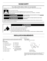
and follow the instructions provided with any tools listed here. Tools needed Parts supplied Check that all parts are included. A ■ Tape measure ■ Masking tape ■ Flat-blade screwdriver ■ Wire strippers ■ Phillips screwdriver nut driver B ■ Level ■ Hammer ■ Hand or electric drill ■ Wrench - Amana AEP222VAW | Installation Instruction - Page 3
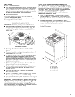
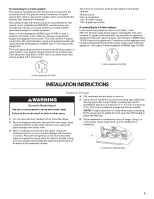
Parts needed If using a power supply cord: ■ A UL listed power supply cord kit marked for use with ranges. The cord should be rated at 250 volts minimum, appliance wiring will need to be revised. See "Electrical Connection" section. Product Dimensions A A. Model/serial rating plate ■ The range - Amana AEP222VAW | Installation Instruction - Page 4
that the range can be moved if servicing is ever necessary. ■ A UL listed conduit connector must be provided at each end of the power supply cable (at the range and at the junction box). ■ Wire sizes and connections must conform with the rating of the range (40 amps). ■ The wiring diagram is located - Amana AEP222VAW | Installation Instruction - Page 5
3-wire receptacle of NEMA Type 10-50R. 3-wire receptacle (10-50R) 4-wire receptacle (14-50R) INSTALLATION INSTRUCTIONS Unpack Range door handle to lift or move the range. 2. Remove shipping materials, tape and film from range. Keep cardboard bottom under range. Remove oven racks and parts - Amana AEP222VAW | Installation Instruction - Page 6
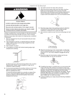
is not flush with cabinet opening edge, align template with overhang. 8. Move the range close to the opening to allow for electrical connections to be made. Remove the shipping base, cardboard or hardboard from under the range. 9. Use a wrench or pliers to lower the front leveling legs one-half - Amana AEP222VAW | Installation Instruction - Page 7
death, fire, or electrical shock. Electrical Shock Hazard Disconnect power before servicing. Use 8 gauge copper or 6 gauge aluminum wire. Electrically ground range. Failure to follow these instructions can result in death, fire, or electrical shock. 1. Disconnect power 2. Remove the terminal block - Amana AEP222VAW | Installation Instruction - Page 8
through the neutral 1. Part of metal ground strap must be cut out and removed. 4. Replace back panel and screws on rear of range. 5. Complete installation following instructions for your type of electrical connection: 4-wire (recommended) 3-wire (if 4-wire is not available) A B C A. Metal - Amana AEP222VAW | Installation Instruction - Page 9
plate on bottom of range. Allow enough slack to easily attach the wiring to the terminal block. A B 3-wire connection: Power Supply volts minimum, 40 amps or 50 amps that is marked for use with nominal 1³⁄₈" (3.5 cm) diameter connection opening, with ring terminals and marked for use with ranges. - Amana AEP222VAW | Installation Instruction - Page 10
local codes prohibit grounding through the neutral 1. Part of metal ground strap must be cut out and removed. 3. Pull the conduit through the strain relief on cord/conduit plate on bottom of range. Allow enough slack to easily attach wiring to the terminal block. A B C G D FE A. Terminal block - Amana AEP222VAW | Installation Instruction - Page 11
A. Terminal block B. Ground-link screw C. Cord/conduit plate D D. Line 2 (red) wire E. Bare (green) ground wire F. Line 1 (black) wire 2. Attach terminal lugs to line 1 (black), bare (green) ground, and line 2 (red) wires. Loosen (do not remove) the set screw on the front of the terminal lug and - Amana AEP222VAW | Installation Instruction - Page 12
. 7. Turn on surface burners and oven. If range does not operate, check the following: ■ Household fuse is intact and tight; or circuit breaker has not tripped. ■ Electrical supply is connected. ■ See "Troubleshooting" in the Use and Care Guide. SURFACE 2 RIGHT REAR OFF HI LO RIGHT FRONT OFF - Amana AEP222VAW | Installation Instruction - Page 13
SEGURIDAD DE LA ESTUFA Su seguridad y la seguridad de los demás es muy importante. Hemos incluido muchos mensajes importantes de seguridad en este manual y en su electrodoméstico. Lea y obedezca siempre todos los mensajes de seguridad. Este es el símbolo de advertencia de seguridad. Este símbolo le - Amana AEP222VAW | Installation Instruction - Page 14
de hoja plana ■ Destornillador Phillips ■ Nivel ■ Martillo ■ Taladro manual o eléctrico ■ Llave de tuercas o pinzas ■ Marcador o Las instalaciones empotradas deberán proveer un recinto cerrado de los lados y la parte posterior de la estufa. ■ Para eliminar el riesgo de quemaduras o incendio - Amana AEP222VAW | Installation Instruction - Page 15
ver el espacio mínimo hasta la parte superior de la superficie de cocción, vea la NOTA. G. Contacto de pared - 8" (20,3 cm) desde cualquier armario H. de 0,020" (0,5 mm). 30" (76,2 cm) de espacio mínimo entre la parte superior de la plataforma de la superficie de cocción y la base de un armario de - Amana AEP222VAW | Installation Instruction - Page 16
tamaño de los hilos y las conexiones deben cumplir con la clasificación de la estufa (de 40 amperios). ■ El diagrama de cableado está ubicado en la parte posterior de la estufa o dentro del cajón de almacenamiento, en una bolsa de plástico transparente. Si se va a conectar a un sistema de 4 hilos - Amana AEP222VAW | Installation Instruction - Page 17
cartón o madera. 1. Saque la plantilla del juego del soporte anti-vuelco (que se encuentra dentro de la cavidad del horno) o de la parte posterior de este manual. 2. Coloque la plantilla sobre el piso, en la abertura del armario, de manera que el extremo izquierdo esté contra el armario y el extremo - Amana AEP222VAW | Installation Instruction - Page 18
seguridad y construcción de casas fabricadas, Título 24 CFR, Parte 3280 (anteriormente conocido como Estándar federal para la seguridad y construcción de casas rodantes, Título 24, HUD Parte 280). Cuando no sea aplicable ese estándar, use el Estándar - Amana AEP222VAW | Installation Instruction - Page 19
muerte, incendio o choque eléctrico. 1. Desconecte el suministro de energía. 2. Quite los tornillos de la tapa del bloque de terminal ubicados en la parte posterior de la estufa. Jale la tapa hacia abajo y hacia usted para sacarla. ■ Apriete el tornillo del protector de cables contra el cable de - Amana AEP222VAW | Installation Instruction - Page 20
A C B A. Tuerca de retención removible - abertura pequeña B. Conector del conducto a través del terminal neutro 1. Parte del fleje de metal a tierra debe cortarse posterior y los tornillos en la parte posterior de la estufa. 5. Complete puesta a tierra, ubicado en la parte posterior de la estufa. Guarde el - Amana AEP222VAW | Installation Instruction - Page 21
3. Haga pasar el cable de suministro de energía a través del protector de cables en la placa del cable/conducto, en la base de la estufa. Deje el hilo lo suficientemente flojo para poder conectar el cableado al bloque de terminal. A B Conexión de 3 hilos: Cable de suministro de energía Use este mé - Amana AEP222VAW | Installation Instruction - Page 22
locales prohíben la conexión a tierra a través del terminal neutro 1. Parte del fleje de metal a tierra debe cortarse y quitarse. G FE A. Bloque ón del hilo desnudo Cómo fijar los talones terminales al bloque de terminal - 20 lbspulg. (2,3 N-m) Calibre del hilo Par de torsión Cobre de calibre 8 - Amana AEP222VAW | Installation Instruction - Page 23
Hilo de la línea 2 (rojo) Especificaciones del par de torsión del hilo desnudo Cómo fijar los talones terminales al bloque de terminal - 20 lbspulg. (2,3 N-m) Calibre del hilo Par de torsión Cobre de calibre 8 Aluminio de calibre 6 25 lbs-pulg. (2,8 N-m) 35 lbs-pulg. (4,0 N-m) 3. Use una llave - Amana AEP222VAW | Installation Instruction - Page 24
doméstico líquido y agua tibia para quitar el residuo ceroso ocasionado por el material de embalaje. Seque meticulosamente con un paño suave. 6. Lea el Manual de uso y cuidado de la estufa para el uso y la limpieza de la estufa. 7. Encienda los quemadores de superficie y el horno. Si la estufa
-
 1
1 -
 2
2 -
 3
3 -
 4
4 -
 5
5 -
 6
6 -
 7
7 -
8
-
9
-
10
-
11
-
12
-
13
-
14
-
15
-
16
-
17
-
18
-
19
-
20
-
21
-
22
-
23
-
24
 |
 |

INSTALLATION INSTRUCTIONS
20" (50.8 CM) FREESTANDING ELECTRIC RANGE
with Standard Clean Oven
INSTRUCCIONES DE INSTALACIÓN
ESTUFA ELÉCTRICA AUTÓNOMA DE 20" (50,8 CM)
con horno de limpieza estándar
Table of Contents/Índice
RANGE SAFETY
.............................................................................
2
INSTALLATION REQUIREMENTS
................................................
2
Tools and Parts
............................................................................
2
Location Requirements
................................................................
3
Electrical Requirements
...............................................................
4
INSTALLATION INSTRUCTIONS
..................................................
5
Unpack Range
..............................................................................
5
Install Anti-Tip Bracket
.................................................................
6
Electrical Connection
...................................................................
7
Verify Anti-Tip Bracket Location
................................................
12
Level Range
................................................................................
12
Complete Installation
.................................................................
12
Check Operation
........................................................................
12
SEGURIDAD DE LA ESTUFA
.......................................................
13
REQUISITOS DE INSTALACIÓN
.................................................
14
Piezas y herramientas
................................................................
14
Requisitos de ubicación
.............................................................
14
Requisitos eléctricos
..................................................................
15
INSTRUCCIONES DE INSTALACIÓN
.........................................
17
Desempaque la estufa
...............................................................
17
Instalación del soporte anti-vuelco
............................................
17
Conexión eléctrica
......................................................................
19
Verificación de la ubicación del soporte anti-vuelco
.................
24
Nivelación de la estufa
...............................................................
24
Complete la instalación
..............................................................
24
Verifique el funcionamiento
........................................................
24
IMPORTANT:
Save for local electrical inspector's use.
IMPORTANTE:
Guarde para tenerlas a disposición del inspector de electricidad local.
W10175654B