Amana AER5524XAD Installation Instruction
Amana AER5524XAD Manual
 |
UPC - 883049214269
View all Amana AER5524XAD manuals
Add to My Manuals
Save this manual to your list of manuals |
Amana AER5524XAD manual content summary:
- Amana AER5524XAD | Installation Instruction - Page 1
FREESTANDING ELECTRIC RANGES Table of Contents RANGE SAFETY 2 INSTALLATION REQUIREMENTS 3 Tools and Parts 3 Location Requirements 3 Electrical Requirements - U.S.A. Only 4 INSTALLATION INSTRUCTIONS 6 Unpack Range 6 Install Anti-Tip Bracket 6 Electrical Connection - U.S.A. Only 7 Verify Anti - Amana AER5524XAD | Installation Instruction - Page 2
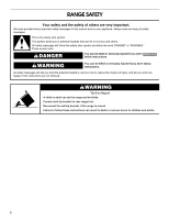
important. We have provided many important safety messages in this manual and on your appliance. Always read and obey all safety messages. This is the reduce the chance of injury, and tell you what can happen if the instructions are not followed. WARNING Tip Over Hazard A child or adult can tip - Amana AER5524XAD | Installation Instruction - Page 3
Parts Gather the required tools and parts before starting installation. Read and follow the instructions the cabinets. ■ Cabinet opening dimensions that are shown must be used. Given dimensions are minimum clearances. ■ appliance wiring will need to be revised. See "Electrical Connection" section. 3 - Amana AER5524XAD | Installation Instruction - Page 4
connection of the equipment-grounding conductor can result in a risk of electric shock. Check with a qualified electrician or service technician if you are in doubt as to whether the appliance is properly grounded. Do not modify the power supply cord plug. If it will not fit the outlet, have - Amana AER5524XAD | Installation Instruction - Page 5
and follow the instructions provided for it the figures in the "Product Dimensions" section of the "Location Requirements line so that the range can be moved if servicing is ever necessary. ■ A UL listed conduit appliance end must be provided at the point the power supply cord enters the appliance - Amana AER5524XAD | Installation Instruction - Page 6
INSTRUCTIONS Unpack Range WARNING Excessive Weight Hazard Use two or more people to move and install range. Failure to do so can result in back or other injury. 1. Remove shipping materials, tape and film from range. 2. Remove oven racks and parts from the back of this manual. 2. Place template on - Amana AER5524XAD | Installation Instruction - Page 7
new 40 amp power supply cord. Plug into a grounded outlet. Failure to follow these instructions can result in death, fire, or electrical shock. Electrical Shock Hazard Disconnect power before servicing. Use 8 gauge copper or 6 gauge aluminum wire. Electrically ground range. Failure to follow these - Amana AER5524XAD | Installation Instruction - Page 8
homes ■ Recreational vehicles ■ In an area where local codes prohibit grounding through the neutral 1. Part of metal ground strap must be cut out and removed. A B C 5. Complete installation following instructions for your type of electrical connection: 4-wire (recommended) 3-wire (if 4-wire is not - Amana AER5524XAD | Installation Instruction - Page 9
3. Feed the power supply cord through the strain relief on the cord/conduit plate on bottom of range. Allow enough slack to easily attach the wiring to the terminal block. A B 3-wire connection: Power Supply Cord Use this method only if local codes permit connecting chassis ground conductor to - Amana AER5524XAD | Installation Instruction - Page 10
New branch-circuit installations (1996 NEC) ■ Mobile homes ■ Recreational vehicles ■ In an area where local codes prohibit grounding through the neutral 1. Part of metal ground strap must be cut out and removed. C G D EF A. Terminal block B. Ground-link screw C. Cord/conduit plate D. Bare (green - Amana AER5524XAD | Installation Instruction - Page 11
6. Use ³⁄₈" nut driver to connect the neutral (white) wire to the center terminal block post with one of the 10-32 hex nuts. G A B F DE C A. 10-32 hex nut B. Line 2 (red) C. Bare (green) ground wire D. Ground-link screw E. Neutral (white) wire F. Line 1 (black) G. Terminal lug 7. Connect line - Amana AER5524XAD | Installation Instruction - Page 12
Verify Anti-Tip Bracket Location 1. On models with a storage drawer, remove storage drawer. See the "Storage Drawer" section. On models with a warming drawer, the rear leg cannot be seen by removing the warming drawer. It will be necessary to view the rear foot from outside the range. Storage - Amana AER5524XAD | Installation Instruction - Page 13
the Use and Care Guide for specific instruction on range operation. If range does not operate, check the following: ■ Household fuse is intact and tight; or circuit breaker has not tripped. ■ Range is plugged into an outlet. ■ Electrical supply is connected. ■ See "Troubleshooting" in the Use and - Amana AER5524XAD | Installation Instruction - Page 14
anti-tip bracket, if the range is moved. Failure to follow these instructions can result in death or serious burns to children and adults. When moving anti-tip bracket. Electrical Shock Hazard Disconnect power before servicing. Replace all parts and panels before operating. Failure to do so can - Amana AER5524XAD | Installation Instruction - Page 15
Left edge ANTI-TIP BRACKET TEMPLATE Cut on dotted lines and place the left edge against the left side cabinet and the top edge against the rear wall. Top edge 15 - Amana AER5524XAD | Installation Instruction - Page 16
W10252706B © 2009. All rights reserved. 9/09 Printed in U.S.A.
-
 1
1 -
 2
2 -
 3
3 -
 4
4 -
 5
5 -
 6
6 -
 7
7 -
8
-
9
-
10
-
11
-
12
-
13
-
14
-
15
-
16
 |
 |

INSTALLATION INSTRUCTIONS
30" (76 CM) FREESTANDING ELECTRIC RANGES
Table of Contents
RANGE SAFETY
...................................................................................
2
INSTALLATION REQUIREMENTS
......................................................
3
Tools and Parts
..................................................................................
3
Location Requirements
......................................................................
3
Electrical Requirements - U.S.A. Only
...............................................
4
INSTALLATION INSTRUCTIONS
........................................................
6
Unpack Range
....................................................................................
6
Install Anti-Tip Bracket
.......................................................................
6
Electrical Connection - U.S.A. Only
...................................................
7
Verify Anti-Tip Bracket Location
......................................................
12
Level Range
......................................................................................
12
Storage Drawer
................................................................................
12
Complete Installation
.......................................................................
13
Moving the Range
............................................................................
14
ANTI-TIP BRACKET TEMPLATE
.....................................................
15
IMPORTANT:
Save for local electrical inspector's use.
W10252706B