Asko W6761 User manual General Use & Care Guide EN - Page 4
Accessories, Installa, Allation Instr, Tion Instr, Tion Instructions, Uctions - front load washer
 |
View all Asko W6761 manuals
Add to My Manuals
Save this manual to your list of manuals |
Page 4 highlights
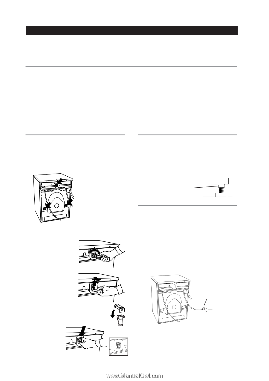
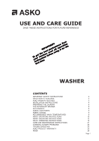
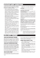
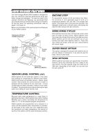
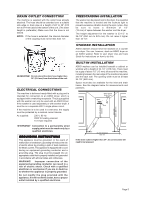
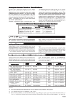
INSTALLATION INSTRUCTIONS Read these instructions carefully and completely before you install the machine. The installation should be carried out by a qualified person who is familiar with all local codes and ordinances for electrical and plumbing connections. SPECIFICATIONS Height Width Depth Weight Rated load Supply voltage Heating element Fuse 33-1/2"-34-1/2 (850-876 mm) 23-7/16" (595 mm) W6761: 23-7/16" (595 mm) W6021/W6441: 24-7/16" (620 mm) 167 lbs. (73 kg) See data plate Single-phase 230 V, 60 Hz 2000 W 15 A (2 internal fuses) IMPORTANT NOTE: Cosmetic damage must be reported to your dealer within five days from the date of purchase. After unpacking the washer, thoroughly check the unit for cosmetic damage. Drum and Barrel Outer casing Mounting Inlet supply hose Supply pressure Outlet hose Stainless steel Stove-enamelled hot-dipped galvanized steel or stainless steel Four adjustable rubber-covered feet 5 ft. (1.5 m) PEX tubing with brass ferrules 15-142 PSI 5.5 ft. (1.7 m) polypropylene hose, 3/4" ID REMOVING THE SHIPPING SUPPORTS The machine is transported with three shipping supports, as illustrated below. These supports hold the tub in place during shipment. When you unpack the machine, you must remove these supports. You must remove the shipping supports before you install the washer. LEVELING THE MACHINE It is important that the machine is level so it won't vibrate excessively during the spinning cycles. Each foot on the washer is adjustable, so you can level the washer on any surface. Once it is level, securely tighten the lock nuts on the feet to prevent excessive vibration during the spin cycles. Be sure to tighten the lock nuts securely when you level the machine. To remove the shipping supports, follow the instructions below: 1. Unscrew the 5/8" (12 mm) bolts holding the supports in place and remove the bolts. 2. Push the rubber spacer 2 up then pull it out of the slot. 1 ACCESSORIES 3. Rotate the spacer so that the extruded end points toward the machine. 4. Insert it into the slot and push down to lock it into position. WATER SUPPLY CONNECTION Because ASKO washers have their own heating element, you only need to have a cold water inlet. The connection should be made by someone who is sufficiently skilled. Use the hose supplied with the washer. (The inlet hose is marked for proper connections.) Water pressure must be in the range of 15-146 PSI. A tap should be fitted on the water supply pipe. If a new supply pipe has been installed for the washer, it should be flushed thoroughly to remove any foreign particles that might clog the strainer in the water inlet. Tap Cold water supply NOTE: If unit is installed on a second story, follow local building codes. We recommend a drip pan be installed. Page 4
-
 1
1 -
 2
2 -
 3
3 -
 4
4 -
 5
5 -
 6
6 -
 7
7 -
 8
8 -
 9
9 -
 10
10 -
11
-
12
-
13
-
14
-
15
-
16
-
17
-
18
-
19
-
20
-
21
-
22
-
23
-
24
-
25
-
26
-
27
-
28
 |
 |